 ?Mathematical formulae have been encoded as MathML and are displayed in this HTML version using MathJax in order to improve their display. Uncheck the box to turn MathJax off. This feature requires Javascript. Click on a formula to zoom.
Abstract
In the current study, a numerical model based on Lagrangian incremental formulation was developed for friction stir process (FSP) of nylon 6 and nylon 6/multiwalled carbon nanotube (MWCNT) composite to investigate the thermomechanical behavior of them (e.g. temperature, effective plastic strain distribution, material flow, and material velocity). For this purpose, FSP was used to disperse the MWCNTs among the polymer matrix of nylon 6, homogenously. The X-ray diffraction and scanning electron microscopy were used to investigate the properties of fabricated nanocomposite. The obtained results were then used to verify the objectives of numerical model. According to the results, the MWCNTs are separated from each other while passing the tool-pin due to high plastic strain applied on them and greater amount of the material accumulates in the AS of stirred zone after passing the tool-pin. Also, MWCNTs were homogeneously and straightly dispersed throughout the nylon 6. The straight and non-curved dispersion of MWCNTs results in growth of its reinforcement capability.
Public Interest Statement
Friction Stir Process (FSP) could modify the outermost layer of polymers without affecting the bulk properties. FSP is generally a structure modification method acting through intense plastic deformation. However, it is an alternative method recently applied to intersperse nanoparticles into the matrix in order to make surface non-composite. In this case, surface of the material changes to a composite with higher mechanical properties without changing bulk of the material.
1. Introduction
Properties of the outermost layer of polymer such as hardness, crystallization, etc. are critically required for a wide range of special applications considering wear resistance, coating, friction, etc. On the other hand, polymers generally do not satisfy the surface properties required for previously mentioned successful applications. Thus, the outermost layer of polymers usually needs to be modified without affecting the bulk properties.
Friction stir process (FSP) is generally a structure modification method acting through intense plastic deformation. However, it is an alternative method recently applied to intersperse nanoparticles into the matrix in order to make surface non-composite. In this case, surface of the material changes to a composite with higher mechanical properties without changing bulk of the material.
During FSP, a tool with a shoulder and pin provides semi-solid state plastic deformation in the work-piece. The tool is rotated and inserted into the work-piece and, then, moved along a specified path. The friction between work-piece and shoulder as well as between the work-piece and pin leads to heat generation and an increase in temperature. It should be noted that, however, it should not reach the melting point of the work-piece.
Nylon 6 is one of the most widely used thermoplastics all over the world. It has various applications such as gears, bearings, accessories, auto parts, power tools housings, and so on. However, special applications cannot be applied successfully to nylon 6 due to lack of special surface properties.
According to the exceptional thermal, mechanical, electrical, optical, and/or other properties of multiwalled carbon nanotubes (MWCNTs), they are widely used as fillers for a wide variety of materials. Several studies have been conducted about approaching a uniform distribution of CNTs among matrix materials, as one of the main issues.
Although numerous studies have been conducted about numerical modeling of FSP and fabrication of composites by FSP, almost all of them are about FSP of metals and, unfortunately, there is little information about FSP of polymers. Barmouz et al. (Citation2011) used FSP method to in situ dispersion of nanoclay particles in high-density polyethylene (HDPE). Liu, Shi, and Zhang (Citation2013) studied the microstructure and mechanical properties of aluminum matrix composite reinforced with MWCNTs. Izadi et al. (Citation2013) fabricated surface composite of Al/SiC prepared by powder metallurgy using FSP method. They produced the surface composite layer with 50–200 μm thickness. Bahrami, Besharati Givi, Dehghani, and Parvin (Citation2014) studied the mechanical properties of Al/SiC joints fabricated by friction stir welding. Sharifitabar, Sarani, Khorshahian, and Shafiee Afarani (Citation2011) investigated the effect of Al2O3 nanoceramic particles on the mechanical properties and microstructure of 5052 Aluminum matrix surface composite. Barmouz and Besharati Givi (Citation2011) used multipass FSP to in situ disperse of the SiC particles throughout the Cu matrix. Cavaliere (Citation2005) evaluated the mechanical properties of 2618 aluminum alloy friction stir processed with 20% of alumina. Pashazadeh, Masoumi, and Teimournezhad (Citation2013) developed a 3D numerical model for friction stir welding (FSW) of copper sheets using the Deform 3D software. In this work, the temperature, effective plastic strain, and material flow behavior of copper were studied during the FSW process. Using Deform 3D software, Asadi, Mahdavinejad, and Tutunchilar (Citation2011) simulated thermomechanical model of AZ91 magnesium alloy for FSP. According to the reports, structural transformations of work-piece were predicted during FSP, in addition to temperature, effective plastic strain, and material flow behavior. Guredoux and Fourment (Citation2009) used Forg3 3D software for FE simulation of three-phase FSW. Zhang and Zhang (Citation2008) developed a fully coupled thermomechanical model where shoulder of the tool plays a significant role on material flow of the upper surface. Buffa, Hua, Shivpuri, and Fratini (Citation2006) used the Deform 3D software for FE simulation of FSW based on Lagrangian incremental formulation. Zhang, Zhang, and Chen (Citation2005) developed a 2D model based on Lagrangian–Eulerian incremental formulation using the Abaqus software. Bahrami et al. (Citation2014) investigated the effect of pin shape on the microstructure and mechanical properties of AA7075/SiC nanocomposite. Carlone and Palazzo (Citation2013) studied the effects of FSW parameters on microstructure of AA2024/T3.
Recently, developing studies were done about FSW of polymers like polyethylene (PE) (Arici & Selale, Citation2007; Arici & Sinmazçelýk, Citation2005; Aydin, Citation2010; Bozkurt, Citation2012; Mostafapour & Azarsa, Citation2012; Rezgui et al., Citation2010; Saeedy & Givi, Citation2011), HDPE (Bozkurt, Citation2012; Rezgui, Trabelsi, Ayadi, & Hamrouni, Citation2011; Squeo & Quadrini, Citation2009), polypropylene (PP) (Kiss & Czigány, Citation2007, Citation2012; Panneerselvam & Lenin, Citation2013), acrylonitrile–butadiene–styrene (Bagheri, Azdast, & Doniavi, Citation2013), polyethylene–terephthalate–glycol (Kiss & Czigány, Citation2012b), and the polyamide Nylon 6 (Panneerselvam & Lenin, Citation2014). Those works can be divided in two categories, according to the type of FSW tool used, i.e. works when conventional FSW tools are used (Arici & Selale, Citation2007; Arici & Sinmazçelýk, Citation2005; Aydin, Citation2010; Bozkurt, Citation2012; Panneerselvam & Lenin, Citation2013, Citation2014; Rezgui et al., Citation2011; Saeedy & Givi, Citation2011; Squeo & Quadrini, Citation2009), similar to that used in FSW of metals, and works in which stationary shoulder tools are used (Bagheri et al., Citation2013; Mostafapour & Azarsa, Citation2012; Kiss & Czigány, Citation2012a, Citation2012b; Rezgui et al., Citation2010).
In the present study, Deform© 3D software was used to develop a 3D Lagrangian-incremental-based model to predict effective plastic strain, temperature, and material flow and velocity in the FSP zone of nylon 6 and nylon 6/MWCNTs. Additionally, FSP was used to disperse the MWCNTs in the polymer matrix of nylon 6; and microstructure of the fabricated surface nanocomposite was evaluated using scanning electron microscopy (SEM). Also, X-ray diffraction (XRD) analysis was used to investigate the homogeneous state of MWCNTs in the polymer matrix.
2. Experimental procedure
The nylon 6 used in this study was commercial grade of TECAST™ supplied by Ensinger Company. The MWCNTs were of carboxyl (MWCNTs-COOH) type and prepared by catalytic chemical vapor deposition method.
Before FSP, a groove with cross section of 1 mm × 6 mm was developed on the work-piece and, then, the MWCNT powder was poured and compressed into the groove. Finally, the FSP tool was plunged inside the work-piece and, then, moved along the developed groove to distribute the MWCNT particles inside the stirred zone of nylon 6 matrix.
Due to the lack of information about the FSP of nylon 6, several trial and errors were conducted to achieve the optimum FSP parameters. A combination of 2,000 rpm and 100 mm/min, respectively, for rotational and traverse speed has been obtained to achieve a proper distribution of MWCNTs and appropriate quality of surface nanocomposite.
To observe the MWCNTs, SEM was operated under acceleration voltages of 5 and 10 kV. The SEM is of field emission-type microscope which works in high and low vacuum cases (for nonconductive samples). XRD patterns of samples were recorded under a voltage of 40 kV and a current of 30 mA for Cu Kα radiation λ = 0.154 nm.
3. Finite element simulation
Deform© 3D software was selected to simulate the FSP of nylon 6 with arbitrary Lagrangian–Eulerian formulation. In this simulation, it was assumed that: (1) the work-piece model is a rigid-viscoplastic material; (2) the material model of tool is rigid; (3) the thermal properties of the tool and work-piece are constant; (4) there is a constant friction coefficient between the tool and work-piece.
Furthermore, the bottom surface of the work-piece was fixed in three main directions. The free surfaces of tool and work-piece were assumed to be in contact with atmosphere at a constant temperature of 20°C.
3.1. Governing equations
As mentioned, the rigid-viscoplastic model was selected as the work-piece material. This model results in nonlinear equations which may be solved by various iterative numerical methods. The rigid-viscoplastic model may be derived from various principles. In this work, the following equation was used for rigid-viscoplastic material (Pashazadeh et al., Citation2013):(1)
(1)
Moreover, the von-Mises was selected as material flow criterion,(2)
(2)
where ,
,
, and
stand for the elements of deviatoric stress, elements of strain rate, effective strain rate, and effective stress, respectively. According to the rigid-viscoplastic material model of work-piece, effective stress is assumed to be related to temperature (T), effective strain rate, and effective plastic strain as follows:
(3)
(3)
3.2. Materials model, boundary conditions, and process parameters
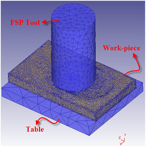
The rigid and rigid-viscoplastic model was selected for the tool and work-piece material, respectively. The tool and work-piece were meshed using tetrahedral minimum mesh sizing method and 0.5 and 0.7 were respectively selected as the minimum mesh size of the tool and work-piece. Figure demonstrates the schematic layout of work-piece and tool. In rigid-viscoplastic model, only the plastic region of deformation was considered and the relation of flow stress-plastic strain at different temperatures of 15, 25, 35, 50, 65, and 80°C and strain rates of 0.33 × 10⁻³, 1.67 × 10⁻³, 3.33 × 10⁻³, and 1.67 × 10⁻² s−1were interpolated in linear space (Shan et al., Citation2007). The stress–strain diagrams of nylon 6 are illustrated in Figure . Table refers to thermal properties of the work-piece, FSP tool, and back-plate. The FSP parameters used in the simulation procedure and actual FSP experiment are given in Table . Due to determination of nylon 6’s mechanical properties to the Deform 3D, the application environment of Deform 3D was prepared for analyze of FSP of nylon 6.
Figure 2. The stress–strain curves of pure nylon 6 at different temperatures for strain rate of (a) 0.33 × 10⁻³; (b) 1.67 × 10⁻³; (c) 3.33 × 10⁻³; (d) 1.67 × 10⁻².
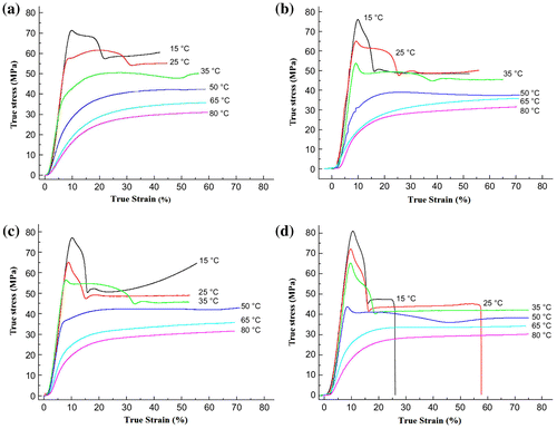
Table 1. Thermal properties of the work-piece and FSP tool, and back-plate
Table 2. The FSP parameters used in the simulation procedure and actual FSP experiment
3.3. Friction model
Constant shear friction model was selected for simulation as follows:(4)
(4)
where f, L, and y indicate to stress resulted by friction, coefficient of friction, and shear yield strength of softer material (work-piece). In order to calibrate the friction coefficient, the temperature predicted by simulation at a point 5 mm away from FSP center line was compared with temperature of the same point in experiment. After several trial and errors, it was observed that the same coefficient, i.e. L = 0.3, remains for simulation and experiment.
4. Results and discussion
4.1. Experimental results
4.1.1. Macro-quality investigation of fabricated surface nanocomposites
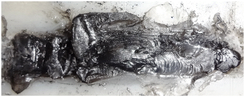
As mentioned, several specimens were produced by different combinations of FSP parameters. According to the findings, heat generation in low rotational speeds was not sufficient to increase the temperature of nylon 6 matrix to its glass transition temperature (Tg) and soften it. Therefore, the nylon 6 matrix has become tattered during FSP. On the other hand, heat generation in high rotational speeds was excessively high and led to PA6 melting. Due to high fluidity of molten PA6 matrix, the FSP became out of control and nylon 6-MWCNTs mixing procedure would not be successful.
Figure illustrates the macro-surface appearance of the specimen fabricated by the optimum combination of 2,000 rpm and 100 mm/min for rotational and traverse speeds, respectively. As illustrated, the nylon 6-MWCNTs mixing procedure was apparently successful in the optimum combinations of FSP parameters.
4.1.2. Dispersion state investigation by XRD patterns
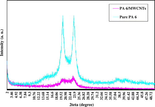
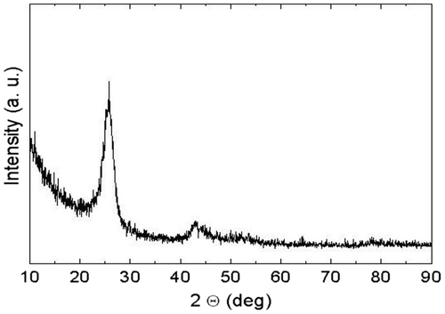
The XRD patterns of pure PA6, pure MWCNTs, and the specimen fabricated by the optimum combination of 2,000 rpm and 100 mm/min for rotational and traverse speeds were compared in order to investigate the effect of MWCNTs on crystallization behavior of PA6. According to Figure , the existence of α form of crystals is reflected as 2θ = 20° and 2θ = 24° for both specimens. The α phase is a crystalline sheets of hydrogen-bounded chains formed between decussate chains. As seen, the intensity of α-phase peaks for neat nylon 6 is higher than that of nylon 6/MWCNTs nanocomposite. On the other hand, significant narrowing can be observed in the α-phase peak of nylon 6/MWCNTs nanocomposite in comparison with neat nylon 6. According to Figure , a peak was observed for pure MWCNTs at 2θ = 25° that cannot be seen in the XRD pattern of nanocomposite specimens (Figure ). It indicates to proper dispersion of MWCNTs in PA6 matrix.
4.1.3. Dispersion state investigation by SEM
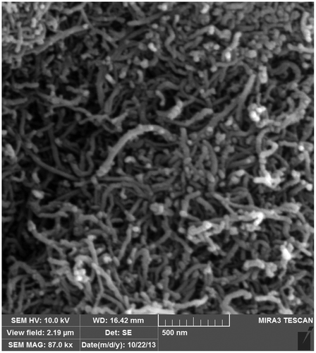
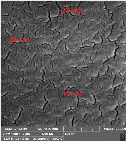
Figure illustrates the MWCNTs observed by SEM. It is clearly seen that the nanotubes are approximately 15–20 nm in diameter and several micrometers in length. Figure shows the SEM observation of homogenous dispersion of MWCNTs in PA6 matrix fabricated in 2,000 rpm and 100 mm/min of rotational and traverse speeds. The contrast variations are due to the scattering difference of electrons from different depths. As shown, the interwoven nanotubes in the nanocomposite are drawn in an approximately straight line contrary to extreme flexible and curved structure of MWCNTs. The straightness of interwoven nanotubes increases the reinforcement capability of MWCNTs provided for the polymeric matrix in comparison with the curvature interwoven nanotubes produced with other traditional methods such as melt-mixing. Also, results of straight dispersion of MWCNTs are very close to that of theoretical reinforcement pointed by Fisher, Bradshaw, and Brinson (Citation2002).
4.2. Finite element simulation results
The temperature distribution, effective plastic strain, and material flow behavior of the work-piece were predicted as follows:
4.2.1. Temperature distribution during FSP
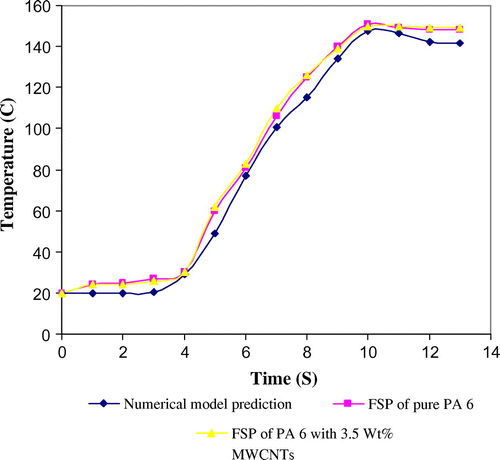
Initially, it is necessary to check the accuracy of the simulated model. For this purpose, it is important to verify it by comparing the results with that of the experimental data. The temperature during FSP of pure nylon 6 and nylon 6 with 3.5 Wt% MWCNTs was measured by thermocouple at a point 5 mm away from the FSP center line. Figure demonstrates the temperature records. It is clearly observed that existence of MWCNTs has no tangible impact on the process temperature and the temperature during FSP of pure nylon 6 is very close to the temperature during FSP of nylon 6 with 3.5 wt% MWCNTs. Also, it is clear that there is a good agreement between simulation predictions and experimental data obtained at 2,000 rpm and 100 mm/min rotational and traverse speeds of the tool.
Figure shows the temperature contours along the tool path after 18 mm tool feed. As illustrated, the peak temperature is 185°C appearing at the interface of tool-shoulder and work-piece. Due to different distributions of strain from advanced side to retreating side and decrease of strain from advanced side to retreating side, the temperature distribution on the interacted surface of work-piece became asymmetric. There is a good agreement between this observation and other studies of FSP of metals (Asadi et al., Citation2011; Pashazadeh et al., Citation2013).
Figure 9. The temperature contours along the tool path after 18 mm tool feed (a) at surface; (b) in midline cross section; (c) in bulk.
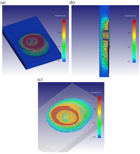
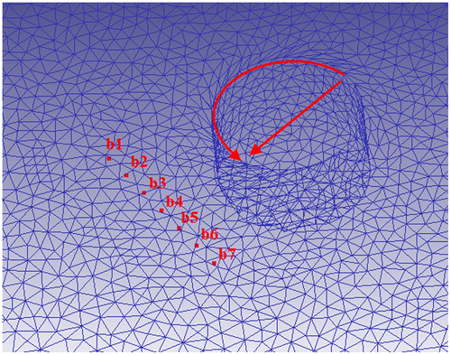
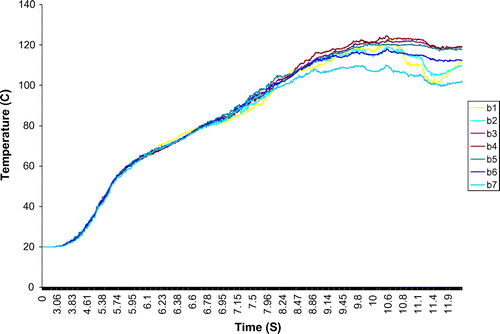
To more accurately investigate temperature of the work-piece, it is necessary to plot the temperature records of points located at advancing and retreating side of work-piece. The points are arranged in steps and depth from surface of 2 mm. Figure shows the schematic location of selected points. As seen, points b1, b2, and b3 are located in advancing side (AS); b4 on the FSP center line; and b5, b6, and b7 in the retreating side (RS). According to Figure , the temperature decreases by moving from the center to AS and RS of stirred zone. The maximum peak temperatures at advancing and retreating side are observed at points b3 and b5 with 124 and 120°C, respectively.
4.2.2. Material flow pattern during FSP
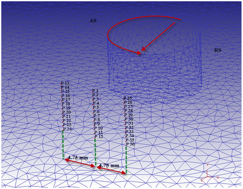
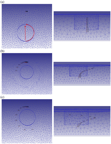
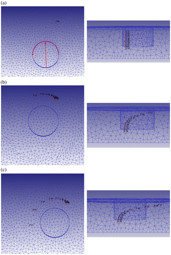
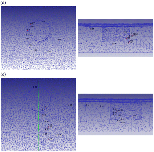
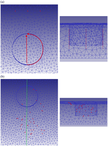
Understanding the material flow behavior of the work-piece during the FSP may be helpful in selecting the optimum tool-pin and tool-shoulder shapes. In this work, the point tracking system was used to trace the selected points when the tool passes through them. These points are located in different depths from surface in increments of 0.5 mm. Figure illustrates the schematic layout of the points selected for flow study during FSP. The points P1–P12, P13–P24, and P25–P36 are located at center line, AS, and RS of stirred zone, respectively. Figure shows the material flow in center line of stirred zone during FSP. As shown, the points P1, P2, P3, P4, P5, and P6 which are close to the tool-shoulder, turn around the tool-pin toward the retreating zone with higher diameter in comparison with tool-pin diameter because the tool-shoulder, in addition to the tool-pin, accelerates the material flow near the top surface. The points P7, P8, P9, and P10 turn around the tool-pin with approximately the same diameter of the tool-pin. The points P11 and P12 illustrate the material flow behavior at the lower side of stirred zone. As seen, the point P11 moves up to the surface while the movement of point P12 is negligible. It is clear that the material close to the lower side of tool-pin moves upward to the stirred zone but the material under the stirred zone is not affected during the FSP. On the other hand, greater amount of the points initially located at center line of FSP accumulate in the AS of stirred zone after passing of the tool-pin. As seen, the final position of aforementioned points is similar to experimental stirred zone.
Figure 13. The material flow in center line of stirred zone during FSP.
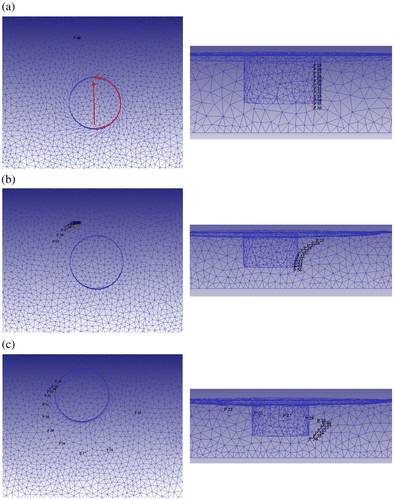
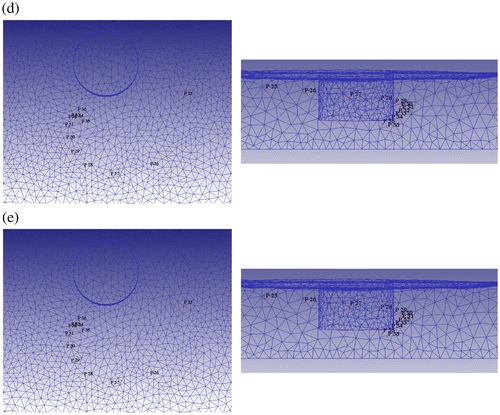
The material flow in the AS and RS of stirred zone are also illustrated in Figures and , respectively. The points P13–P24, initially located in the AS, rotate around the tool-pin and finally gather in the AS of stirred zone. However, the points P25–P36 do not behave like the points P1–P24 and most of them gather in the RS of stirred zone after passing of the tool-pin.
Figure 14. The material flow in AS of stirred zone during FSP.
Figure 15. The material flow in RS of stirred zone during FSP.
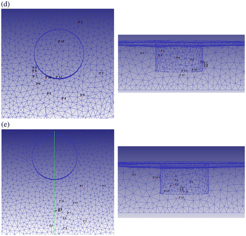
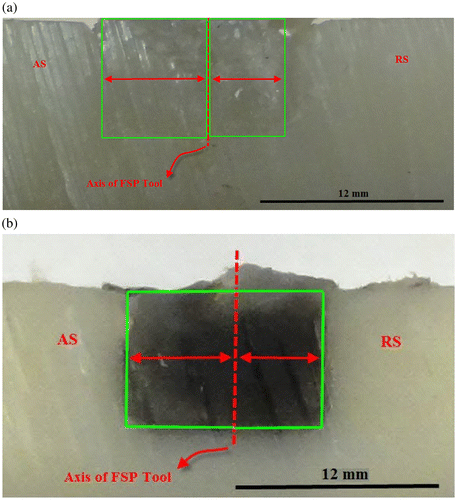
Figure shows a general view of flow pattern for better understanding of material flow in the stirred zone. Accordingly, most of stirred zone material gathers in the AS after rotating around the tool-pin. This phenomenon was clearly observed in the experimental stirred zone. Figure (a) and (b) show the cross section of stirred zone for pure nylon 6 and mixture of nylon 6/MWCNTs, respectively. As seen, area of the left side of FSP tool axis (AS) is larger than that of the right side of FSP tool axis (RS). It means that greater amount of nylon 6 gathered in the AS of stirred zone after rotating around the pin. The accumulation in the AS of stirred zone for metals has been reported by Lorrain, Favier, Zahrouni, and Lawrjaniec (Citation2010) and Asadi et al. (Citation2011), too.
4.2.3. Dispersion pattern of MWCNTs throughout nylon 6 during FSP
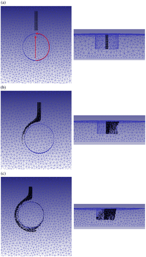
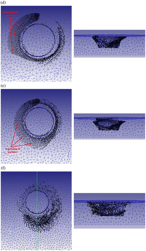
According to the obtained results from experimental FSP of nylon 6/MWCNTs, the interwoven nanotubes were well separated and distributed throughout the nylon 6 matrix. This phenomenon can be explained by evaluating the movement patterns of MWCNTs during FSP. Figure shows the dispersion pattern of MWCNTs throughout nylon 6 during FSP. The agglomerates of MWCNTs were considered as small cubes and were arranged in a space with cross section of 1 mm6 mm. As seen, the MWCNTs are well separated from each other while passing the tool-pin due to high plastic strain applied on them. This phenomenon makes opens the MWCNT bundles and creates a homogeneous distribution of MWCNTs throughout nylon 6 matrix. On the other hand, it is clearly observed that a greater amount of the MWCNTs gets accumulated in the AS of stirred zone after passing the tool-pin. The final position of mentioned points is similar to experimental stirred zone (Figure (b)) except the points located on the upper left side of stirred zone which will be explained. The interesting behavior of these points is due to frictional force of shoulder which results in rotation of them with shoulder.
Figure 18. Dispersion pattern of MWCNTs through out nylon 6 during FSP.
4.2.4. Strain, strain rate, and velocity evaluation during FSP
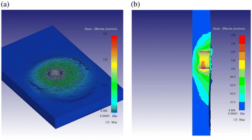
It is well known that the work-piece, during the FSP, is affected by high plastic deformations under high pressure. Figure (a) illustrates the effective plastic strain counters along the tool path after 18 mm tool feed. For more detailed information, the tool path cross section is presented in Figure (b), too. It is obvious that the effective plastic strain decreases from top surface to bottom because the tool-shoulder accelerates the material flow near the top surface.
Figure (a), (b), and (c) shows the historic curves of effective plastic strain for points P1–P12, P13–P24, and P25–P36, respectively. It is clearly seen that the effective plastic strain decreases upon moving from top surface to the root of stirred zone which is similar to presented works for metals (Asadi et al., Citation2011; Lorrain et al., Citation2010; Pashazadeh et al., Citation2013). The effective plastic strain of near-surface points are higher than other points because the shoulder increases the plastic deformation of near-surface points and intensifies the effective plastic strain of them. On the other hand, it is clearly seen that the effective plastic strain of the AS is greater than that of RS. Thus, material shearing mostly occurs at the advancing side.
Figure 20. The historic curves of effective plastic strain for points (a) P1–P12; (b) P13–P24; (c) P25–P36.
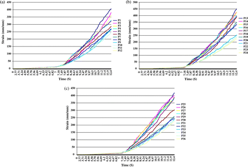
As can be seen in Figure , the effective plastic strain for the points located in mid-depth of stirred zone is about 270 mm/mm which can be considered as the average strain () (Mishra & Ma, Citation2005). Also, the major effective plastic strain variation started from approximately the 7th second and increased almost linearly until the end of process. Thus, the average strain rate can be calculated as
.
As reported (Chang, Lee, & Huang, Citation2004), the average strain rate during FSP () is proportional to angular speed of tool-pin (ω), tool-pin radius (R), and depth of stirred zone (L):
(5)
(5)
where k stands for constant value which depends on the FSP conditions. According to the work of Chang et al. (Citation2004), the k value is considered as 0.1. In this study, the angular speed of tool-pin, tool-pin radius, and depth of stirred zone are 209.34 rad/s (for 2,000 rpm of spindle speed), 5, and 6 mm, respectively. The average strain rate calculated from Equation 5 is about 54.78 s−1. As seen, there is a good agreement between numerical model prediction and empirical Equation 5.
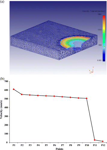
Furthermore, Figure (a) and (b) illustrate the velocity contour of material and the velocity of points P1–P12 during FSP, respectively. As can be expected, the velocity of points decreases by moving from top surface to the root of stirred zone. Also, the velocity of points P11 and P12 located in the sub-region of stirred zone have significant difference compared to the points located in the stirred zone. This phenomenon validates the results of presented work by Morisada, Fujii, Kawahito, Nakata, and Tanaka (Citation2011) which used XRD to evaluate the velocity of material in stirred zone but the reported velocities have significant difference compared to results of current study which is attributed to the difference of material.
5. Conclusions
The present study investigated the FSP in dispersing the MWCNTs throughout the polymer matrix of nylon 6 to fabricate surface nanocomposite. Also, the thermo-mechanical properties such as temperature, effective plastic strain distribution, material velocity distribution, material flow of PA6, and dispersion pattern of MWCNTs throughout nylon 6 matrix were successfully predicted using finite element simulation.
Frequent trial-and-error experiments were conducted to achieve the proper combination of FSP parameters (rotational and traverse speed). The SEM observation and XRD patterns indicate homogenous and fine distribution of MWCNTs throughout the polymer matrix of nylon 6. Also, the SEM observation indicates that the interwoven nanotubes in the matrix are drawn in an approximately straight line. Straight and noncurved dispersion of MWCNTs increases its reinforcement capability and, thus, makes the experimental reinforcement results closer to that of theoretical one.
The finite element simulation was based on Lagrangian incremental formulation and experimental FSP was conducted to verify the predicted outcomes. Comparing the result of simulation and experimental FSP refers to good agreement between simulation predictions and actual observations. Temperature distribution study shows that the peak temperature appears at the interface of tool-shoulder/work-piece and the temperature distribution on the interacted surface is asymmetric. Also, the more the distance from center of the tool the less the temperature at the stirred zone. On the other hand, the analysis of effective plastic strain indicates that the material shearing of advancing side is higher than that of the retreating zone and effective plastic strain decreases upon moving from top surface to root of stirred zone. Finally, the flow behavior of nylon 6 and dispersion pattern of MWCNTs throughout nylon 6 were successfully predicted. Results revealed that the MWCNTs are separated from each other, while passing the tool-pin due to high plastic strain applied on them. Also, greater amount of the material accumulate in the AS of stirred zone after passing of the tool-pin.
Additional information
Funding
Notes on contributors
Reza Farshbaf Zinati
Reza Farshbaf Zinati holds a PhD in Mechanical Engineering from AmirKabir University of Tehran. He became a faculty member of Mechanical Engineering Department at Tabriz Branch of Islamic Azad University in 2012. His group research focuses on machining, traditional metal cutting, non-traditional processes, friction stir process (FSP), finite element simulation of FSP, polymer-based nanocomposites.
Notes
This article has been retracted. Please see Retraction Statement (http://dx.doi.org/10.1080/23311916.2015.1106100)
References
- Arici, A., & Selale, S. (2007). Effects of tool tilt angle on tensile strength and fracture locations of friction stir welding of polyethylene. Science and Technology of Welding and Joining, 12, 536–539.10.1179/174329307X173706
- Arici, A., & Sinmazçelýk, T. (2005). Effects of double passes of the tool on friction stir welding of polyethylene. Journal of Materials Science, 40, 3313–3316.10.1007/s10853-005-2709-x
- Asadi, P., Mahdavinejad, R. A., & Tutunchilar, S. (2011). Simulation and experimental investigation of FSP of AZ91 magnesium alloy. Materials Science and Engineering: A, 528, 6469–6477.10.1016/j.msea.2011.05.035
- Aydin, M. (2010). Effects of welding parameters and pre-heating on the friction stir welding of UHMW-polyethylene. Polymer-Plastics Technology and Engineering, 49, 595–601.10.1080/03602551003664503
- Bagheri, A., Azdast, T., & Doniavi, A. (2013). An experimental study on mechanical properties of friction stir welded ABS sheets. Materials & Design, 43, 402–409.10.1016/j.matdes.2012.06.059
- Bahrami, M., Besharati Givi, M. K., Dehghani, K., & Parvin, N. (2014). On the role of pin geometry in microstructure and mechanical properties of AA7075/SiC nano-composite fabricated by friction stir welding technique. Materials & Design, 53, 519–527.10.1016/j.matdes.2013.07.049
- Barmouz, M., & Besharati Givi, M. K. (2011). Fabrication of in situ Cu/SiC composites using multi-pass friction stir processing: Evaluation of microstructural, porosity, mechanical and electrical behavior. Composites Part A: Applied Science and Manufacturing, 42, 1445–1453.10.1016/j.compositesa.2011.06.010
- Barmouz, M., Seyfi, J., Besharati Givi, M. K., Hejazi, I., & Davachi, S. M. (2011). A novel approach for producing polymer nanocomposites by in situ dispersion of clay particles via friction stir processing. Materials Science and Engineering: A, 528, 3003–3006.
- Bozkurt, Y. (2012). The optimization of friction stir welding process parameters to achieve maximum tensile strength in polyethylene sheets. Materials & Design, 35, 440–445.10.1016/j.matdes.2011.09.008
- Buffa, G., Hua, J., Shivpuri, R., & Fratini, L. (2006). Design of the friction stir welding tool using the continuum based FEM model. Materials Science and Engineering: A, 419, 381–388.10.1016/j.msea.2005.09.041
- Carlone, P., & Palazzo, G. S. (2013). Influence of process parameters on microstructure and mechanical properties in AA2024-T3 friction stir welding. Metallography, Microstructure, and Analysis, 2, 213–222.10.1007/s13632-013-0078-4
- Cavaliere, P. (2005). Mechanical properties of friction stir processed 2618/Al2O3/20p metal matrix composite. Composites Part A: Applied Science and Manufacturing, 36, 1657–1665.10.1016/j.compositesa.2005.03.016
- Chang, C. I., Lee, C. J., & Huang, J. C. (2004). Relationship between grain size and Zener–Holloman parameter during friction stir processing in AZ31 Mg alloys. Scripta Materialia, 51, 509–514.10.1016/j.scriptamat.2004.05.043
- Fisher, F. T., Bradshaw, R. D., & Brinson, L. C. (2002). Effects of nanotube waviness on the modulus of nanotube-reinforced polymers. Applied Physics Letters, 80, 4647–4649.10.1063/1.1487900
- Guerdoux, S., & Fourment, L. (2009). A 3D numerical simulation of different phases of friction stir welding. Modelling and Simulation in Materials Science and Engineering, 17, 075001.10.1088/0965-0393/17/7/075001
- Izadi, H., Nolting, A., Munro, C., Bishop, D. P., Plucknett, K. P., & Gerlich, A. P. (2013). Friction stir processing of Al/SiC composites fabricated by powder metallurgy. Journal of Materials Processing Technology, 213, 1900–1907.10.1016/j.jmatprotec.2013.05.012
- Kiss, Z., & Czigány, T. (2007). Applicability of friction stir welding in polymeric materials. Periodica Polytechnica Mechanical Engineering, 51, 15–18.
- Kiss, Z., & Czigány, T. (2012a). Microscopic analysis of the morphology of seams in friction stir welded polypropylene. Express Polymer Letters, 6, 54–62.
- Kiss, Z., & Czigány, T. (2012b). Effect of welding parameters on the heat affected zone and the mechanical properties of friction stir welded poly(ethylene-terephthalate-glycol). Journal of Applied Polymer Science, 125, 2231–2238.10.1002/app.36440
- Liu, P., Shi, Q. Y., & Zhang, Y. B. (2013). Microstructural evaluation and corrosion properties of aluminium matrix surface composite adding Al-based amorphous fabricated by friction stir processing. Composites Part B: Engineering, 52, 137–143.10.1016/j.compositesb.2013.04.019
- Lorrain, O., Favier, V., Zahrouni, H., & Lawrjaniec, D. (2010). Understanding the material flow path of friction stir welding process using unthreaded tools. Journal of Materials Processing Technology, 210, 603–609.10.1016/j.jmatprotec.2009.11.005
- Mishra, R. S., & Ma, Z. Y. (2005). Friction stir welding and processing. Materials Science and Engineering: R: Reports, 50, 1–78.10.1016/j.mser.2005.07.001
- Morisada, Y., Fujii, H., Kawahito, Y., Nakata, K., & Tanaka, M. (2011). Three-dimensional visualization of material flow during friction stir welding by two pairs of X-ray transmission systems. Scripta Materialia, 65, 1085–1088.10.1016/j.scriptamat.2011.09.021
- Mostafapour, A., & Azarsa, E. (2012). A study on the role of processing parameters in joining polyethylene sheets via heat assisted friction stir welding: Investigating microstructure, tensile and flexural properties. International Journal of Physical Sciences, 7, 647–654.
- Panneerselvam, K., & Lenin, K. (2013). Effects and defects of the polypropylene plate for different parameters in friction stir welding process. International Journal of Engineering Research and Technology, 2, 143–152.
- Panneerselvam, K., & Lenin, K. (2014). Joining of nylon 6 plate by friction stir welding process using threaded pin profile. Materials & Design, 53, 302–307.10.1016/j.matdes.2013.07.017
- Pashazadeh, H., Masoumi, A., & Teimournezhad, J. (2013). A 3D numerical model to investigate mechanical, thermal, and material flow characteristics in friction stir welding of copper sheets. International Journal of Automotive Engineering, 3, 328–342.
- Rezgui, A., Ayadi, M., Cherouat, A., Hamrouni, K., Zghal, A., & Bejaoui, S. (2010). Application of Taguchi approach to optimize friction stir welding parameters of polyethylene. EPJ Web of Conferences, 6, 1–8.
- Rezgui, M., Trabelsi, A., Ayadi, A., & Hamrouni, K. (2011). Optimization of friction stir welding process of high density polyethylene. International Journal of Production and Quality Engineering, 2, 55–61.
- Saeedy, S., & Givi, M. (2011). Investigation of the effects of critical process parameters of friction stir welding of polyethylene. Proceedings of the Institution of Mechanical Engineers, Part B: Journal of Engineering Manufacture, 225, 1305–1310.10.1243/09544054JEM1989
- Shan, G. F., Yang, W., Yang, M. B., Xie, B. H., Feng, J. M., & Fu, Q. (2007). Effect of temperature and strain rate on the tensile deformation of polyamide 6. Polymer, 48, 2958–2968.10.1016/j.polymer.2007.03.013
- Sharifitabar, M., Sarani, A., Khorshahian, S., & Shafiee Afarani, M. (2011). Fabrication of 5052Al/Al2O3 nanoceramic particle reinforced composite via friction stir processing route. Materials & Design, 32, 4164–4172.10.1016/j.matdes.2011.04.048
- Squeo, E., & Quadrini, F. (2009). Friction stir welding of polyethylene sheets. Galati: The Annals of DUNA˘REA DE JOS University of Galati, Fascicle V Technologies in Machine Building. ISSN 1221-4566.
- Zhang, H. W., Zhang, Z., & Chen, J. T. (2005). The finite element simulation of the friction stir welding process. Materials Science and Engineering: A, 403, 340–348.10.1016/j.msea.2005.05.052
- Zhang, Z., & Zhang, H. W. (2008). A fully coupled thermo-mechanical model of friction stir welding. The International Journal of Advanced Manufacturing Technology, 37, 279–293.10.1007/s00170-007-0971-6

