 ?Mathematical formulae have been encoded as MathML and are displayed in this HTML version using MathJax in order to improve their display. Uncheck the box to turn MathJax off. This feature requires Javascript. Click on a formula to zoom.
Abstract
The main topic of this paper is the dynamic modeling of a hybrid energy system based on an anion exchange membrane fuel cell (AEMFC). The objective was to develop a dynamic model, able to describe the system behavior and the response of components to sudden load changes. The overall model design includes other different subsystems, represented by electric dipoles or double dipoles. In addition to the two power sources, AEMFC and battery pack, there is a DC-DC buck converter, interjected between them, whose function is to decrease AEMFC voltage to bus voltage set by a battery pack and to smooth this voltage, thereby serving the load properly. Above all, there is a step time-varying dc load and a power management block, for the managing of energy flows through the system. The whole model was implemented in Matlab–Simulink environment. The main outputs of DC-DC buck converter and battery dynamic models were validated respectively with the data of other equally detailed reference simulation models and with experimental data found in the literature. In this paper, the design of a discrete intervals power management strategy to manage the connection/disconnection of the AEMFC was made and the hybrid managed energy system calculation code was used to evaluate the time trends of AEMFC and battery pack electric powers, of battery pack state of charge, of DC-DC buck converter and entire hybrid system efficiencies for different initial battery pack states of charge and different step time-varying dc loads.
Public Interest Statement
Hydrogen is a promising solution for the storage of renewable energies and can be seen as a potential energy vector for the future. One of the alternative sources of electric power is the fuel cell, which offers many advantages such as high efficiency, high power density, absence of combustion, silent technology and the flexibility to be stored anywhere.
There is a certain variety of fuel cell-battery hybrid systems, whose main components are fuel cell, DC-DC converter, battery and/or super-capacitors. They are applied for the propulsion of different types of green vehicles, but they can also be used in a stationary situation.
In this article, a numerical dynamic simulation model of a hybrid system with AEMFC and Li-ion batteries is formulated and implemented in Matlab–Simulink environment. It includes a discrete logic power management strategy, which was ad hoc designed to satisfy a specific electric load.
1. Introduction
If one of the major challenges of this century is the reduction of fossil fuel consumption and greenhouse gas emissions, then hydrogen is a promising solution for the storage of renewable energies and can be seen as a potential energy vector for the future. The increase in the use of renewable resources is remarkable and accepted globally. One of the alternative sources of electric power is the fuel cell, which is a promising form of renewable energy that offers many advantages such as high efficiency, high power density, absence of combustion, silent technology and the flexibility to be stored anywhere (Dyer, Citation2002; Wang, Chen, Mishler, Chan, & Cordobes, Citation2011; Wee, Citation2007).
There is a certain variety of kinds of fuel cell-battery hybrid systems. Each of these hybrid systems has a different layout, but in all these hybrid systems fuel cell, DC-DC converter, battery and/or supercapacitors are the main components. They are applied for the propulsion of different type of green vehicles such as light vehicles, bikes, motorbikes (De Luca, Fragiacomo, De Lorenzo, Czarnetzki, & Schneider, Citation2016; Hwang & Chang, Citation2012; Pachauri & Chauhan, Citation2015; Rabbani, Rokni, Hosseinzadeh, & Mortensen, Citation2014) buses (De Lorenzo et al., Citation2014), tourist boats (Choi et al., Citation2016) and aircraft (Nishizawa, Kallo, Garrot, & Weiss-Ungethüm, Citation2013), but they can also be used in a stationary plant (El-Shater, Eskander, & El-Hagry, Citation2006; Gang & Kwon, Citation2016; Hyun et al., Citation2013; Olgun et al., Citation2006). The fuel cell is the chief energy source of the whole hybrid system. Compared with fuel cells, lithium rechargeable batteries have a rapid transient response without any warm up or start up time, and their specific power capability is also much higher than that of fuel cells. Combining fuel cells with batteries yields hybrid power sources that make the best use of the advantages of each individual device and can meet the requirements for both high power and energy densities (Gao, Jiang, & Dougal, Citation2004). This kind of hybrid energy system can be an important solution to problems like the slow response of FC and inconstant voltage output when the current changes. In fact, the presence of battery or other types of bridge power can be very useful to work together with the fuel cell in order to have a good output performance and quick dynamic response, solving load-tracking issues (Gao et al., Citation2004; Thounthong, Raël, & Davat, Citation2009).
A dynamic approach to the problem is essential, owing to the fact that electrical devices such as power-converters, batteries and mostly fuel cell, involve dynamic phenomena, so an accurate characterization is necessary to analyze transient states better, without losing any accuracy through the different components.
In the literature there are some articles about the numerical modeling of the hybrid system components and of the whole hybrid system (Arges, Ramani, & Pintauro, Citation2010; Chao & Shieh, Citation2012; Merle, Wessling, & Nijmeijer, Citation2011; Suhn & Stefanopoulou, Citation2005; Wang, Ou, & Kim, Citation2015). Some articles focus their attention on the hybrid system control systems (Chao & Shieh, Citation2012; Suhn & Stefanopoulou, Citation2005; Wang et al., Citation2015), anyway all these articles consider a Proton Exchange Membrane Fuel Cell (PEMFC) as fuel cell.
The fuel cell presented in this article is an H2/O2 Anion Exchange Membrane Fuel Cell (AEMFC), which is a low temperature fuel cell and, similarly to PEMFC, uses a polymer membrane as electrolyte. Essentially, the AEMFC is an alkaline fuel cell, in which the role of electrolyte is bestowed to a solid membrane, instead of an aqueous KOH solution commonly used in a typical AFC. The size and weight of the fuel cell are variable and this enlarges the domain of application. The main idea behind employing an anion exchange membrane (AEM) in an AFC is to improve the AFC efficiency and useful life (slow down performance degradation with time) (Arges et al., Citation2010; Merle et al., Citation2011). Some advantages of using this kind of fuel cell are an easier reaction process in alkaline environment compared to acidic one, better kinetics and higher flexibility in terms of fuel and ORR (Oxygen Reduction Reaction) catalyst (Arges et al., Citation2010; Smitha, Sridhar, & Khan, Citation2005; Ünlü, Zhou, & Kohl, Citation2009).
In this article, a numerical dynamic simulation model of a hybrid system with AEMFC and Li-ion batteries is formulated and implemented in Matlab–Simulink environment, using the SimPower Systems library, which is the most appropriate to represent and analyze electric circuits. The hybrid system presented has the peculiarity of having been modeled to highlight electric connections topology. Moreover, it includes a discrete logic control to manage energy flows, which was ad hoc designed to satisfy a specific electric load.
2. The overall system model and its components
The key point in a hybrid system is how to control the power flow in the right way to meet the requirement of the load (Thounthong et al., Citation2009).
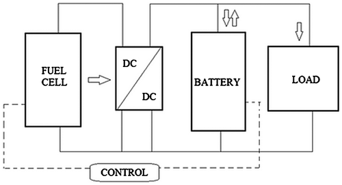
The proposed hybrid system is composed of the following subsystems (Figure ):
| • | AEMFC (1.2 kW nominal power), whose numerical model is described in more details in another article of the same authors (Fragiacomo et al., Citation2016); | ||||
| • | lithium ion battery package (19.2 V nominal voltage); | ||||
| • | DC-DC buck converter; | ||||
| • | electric load block; | ||||
| • | control subsystem. | ||||
Figure shows the overall system configuration; as it can be easily noticed, the load is parallel connected to the energy sources. The bus voltage, supplying load, is set by the battery package and its nominal value is equal to 19.2 V.
2.1. The AEMFC
The fuel cell model was developed in another article by the same authors (Fragiacomo et al., Citation2016) taking into account both electrochemical and thermal behavior of the device, considering constant reactants input flow rates and temperature control at a set point of 65°C by a convective coolant system. The electrochemical model considered the different dynamic phenomena taking place during fuel cell operations: starting from the ideal Nernst voltage, each loss was modeled (activation, ohmic, concentration, fuel crossover) according to partial pressures calculation on both electrodes (Chen, Citation2011). The dynamics of the partial pressure of hydrogen at the anode and the partial pressure of oxygen at the cathode follow the ideal gas law derived over time that is also equal to net molar flow balance through each electrode. In the fuel cell system model, the excess hydrogen was considered to be re-circulated to the anode and the throttle is assisted to regulate the inlet flow rate of hydrogen at the proper tank pressure (Chen, Citation2011); in this way it will result that all the hydrogen entering the fuel cell will cause a reaction.
The thermal model is based on the thermal energy balance: only a fraction of the internal energy contained in the hydrogen can be converted into electricity, while the remaining energy is either dissipated or absorbed by the fuel cell as heat (San Martín, Ursúa, & Sanchis, Citation2014), leading to an increase in the fuel cell operating temperature. The balance of power making up the heat generation is due to the heating power released by the chemical reaction, the electrical power generated by the fuel cell and the heating power associated with the sensible and latent heat of the reactants (hydrogen and oxygen) and the reaction product (water) (San Martín et al., Citation2014). In (San Martín et al., Citation2014), the heating power dissipated by convection transfer is due to a variable rotation speed fan, with a closed loop control on temperature by mean of a Proportional Integral (PI) regulator. The calculation code based on the AEMFC electric model in (San Martín et al., Citation2014) reproduces, as output, the polarization curve of the 1.2 kW AEMFC fuel cell, which was validated experimentally with experimental data in (San Martín et al., Citation2014). Once the subsystem provides a voltage output, it can be easily connected by mean of its terminals to the rest of the hybrid system electric circuit that is developed in this article.
The AEMFC electric efficiency is defined by Equation (1):(1)
(1)
where PAEMFC, and
are respectively the electric power produced by AEMFC, the mass flow of hydrogen at the inlet of fuel cell and the low heating value of hydrogen.
is constant and equal to the mass flow of hydrogen that guarantees the maximum fuel cell power for a defined electric load with a maximum hydrogen utilization factor of 0.9. When the electric load is under its maximum value the effective AEMFC efficiency can be higher than the defined AEMFC electric efficiency if the hydrogen at the anode outlet is recirculated to the anode inlet.
2.2. DC-DC converter model
Nowadays, DC-DC power converters are employed in a wide variety of applications; a generic static converter is an electrical circuit which can control the transfer of energy between a generator and a receiver. The input to a DC-DC converter is an unregulated dc voltage and during its operation the converter produces a regulated output voltage, having a magnitude that differs from the input one (Erickson, Citation1999–2014). The ideal DC-DC converter exhibits 100% efficiency; in practice, efficiencies of 70–95% are typically obtained. This is achieved using switched-mode, or chopper, circuits whose elements dissipate negligible power (Erickson, Citation1999–2014; Kumari, Citation2011). The most common strategy for controlling the power transmitted to the load by Pulse Width Modulation (PWM).
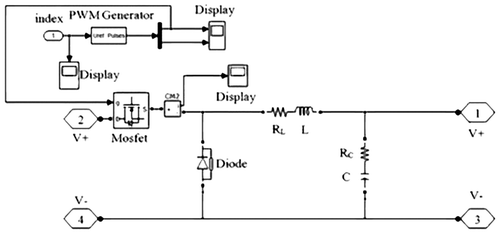
The modeled device is a step-down converter that decreases the fuel cell output voltage to a lower value, set by the battery pack. Its role is also to stabilize the voltage, cutting undesired harmonics of the switching frequency contained in the voltage waveform; this is possible thanks to single-section L-C low-pass filter, included in the converter circuit (Erickson, Citation1999–2014). Filter corner frequency is determined by inductance and capacitance, which are essentially adjustable parameters. The converter subsystem is a double dipole, whose two ports are respectively connected to the fuel cell terminals and to battery/load bus, controlling the transfer of energy between the source and the receiver. Figure shows converter subsystem; the electric circuit includes resistive effects (RL, RC) on the inductive branch and on the capacitive one. Diode and Mosfet blocks are modeled as real components with on-state resistances (Ron diode, Ron FET), snubber resistances (Rs diode, Rs FET) and capacitances (Cs diode, Cs FET) inside. The transistor gate is driven by a PWM Generator output signal that consists of a I/O switching pulse, whose duty cycle is according to the input index, in turn according to the control block. The DC-DC converter subsystem is interjected between Fuel Cell block and Load block. The left door (terminals 2 and 4) is connected to fuel cell output, whereas the right door (terminals 1 and 3) is connected to the load and to the battery pack. Electric quantities are summarized in Table . The PWM Generator, acting as control for the DC-DC converter, was designed in a specific way using as modulating signal not a typical sinusoidal waveform, but a constant signal. The modulating signal value, always included between 0 and 1, is determined by the control block which outputs a certain constant signal according to power control logic of fuel cell, batteries state of charge and load size. The modulating signal is the one compared to the carrier signal that is represented by a triangular waveform starting from 0, decreasing to −1, rising to 1 and then returning to 0: the designed PWM block uses a carrier frequency of 1,080 Hz and a one-arm bridge generation mode so that it means there will be two complementary pulses signals. Each value of modulating signal will correspond to a different duty cycle in PWM output signal, in particular, a higher value of modulating signal will give a greater duty cycle. When the input voltage decreases, the value of modulating signal increases. The DC-DC converter model was validated using a reference model (Padhee, Pati, & Mahapatra, Citation2015; Van Dijk, Spruijt, O’Sullivan, & Klaassens, Citation1995) based on a closed loop configuration with a PI regulator acting on the voltage error signal. The PI controller was designed using a proportional gain equal to 0.068 and an integral gain equal to 0.34 whereas the reference voltage value was set to 8 V.
Table 1. Converter circuit parameters
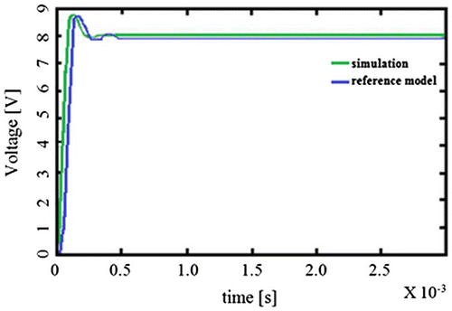
The simulations performed in order to prove model soundness, showed well-matching results with reference paper (Shepherd, Citation1965; Van Dijk et al., Citation1995), in terms of converter output voltage. Figure shows a comparison between the model output voltage and the reference model voltage: after a short transient state, quantifiable in around 0.6 ms, both waveforms reach a quasi-steady state around the set voltage value, with a ripple of 0.03 V. The average DC-DC converter electric efficiency is defined by Equation (2):(2)
(2)
where and
are respectively the average electric powers at the outlet and at the inlet of DC-DC converter.
2.3. Battery model
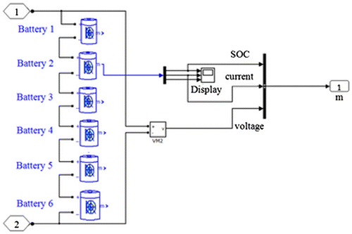
The chosen battery type was a Lithium Ion battery: this category belongs to the rechargeable batteries family. Lithium ions move from the negative electrode to the positive one during discharge and in reverse mode when charging. The electrolyte, which allows for ionic movement, and the two electrodes are the consistent components of a lithium-ion cell. The battery stack model, represented in Figure , is made up of a series of six batteries to achieve a total output nominal voltage of 19.2 V; the battery subsystem block is connected to the load block, in the whole circuit, by mean of the two voltage terminals 1 and 2 shown in Figure . The Battery block implements a generic dynamic model parameterized to represent most popular types of rechargeable batteries. The equivalent circuit of the generic battery model is shown in Figure . The main equations of the generic battery model specialized for a Lithium-Ion battery are the Equation (3) (Shepherd, Citation1965; Tremblay, Dessaint, & Dekkiche, Citation2007):(3)
(3)
Figure 5. Equivalent circuit of the generic battery model (Shepherd, Citation1965; Tremblay et al., Citation2007).
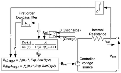
where E0, K, Q, it, i*,i, A and B are respectively the constant voltage, the polarization resistance, the maximum battery capacity, the extracted capacity, the low frequency current dynamics, the battery current, the exponential voltage and the exponential capacity.
Each one of the six batteries shown in Figure was “ad hoc” designed by defining specific battery parameters, to reproduce CALB CA40 battery behavior, a real device commercially available (Li-Ion Battery commercial data sheet available on “https://www.calbusainc.com/” in 2017).
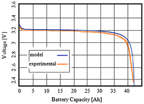
Table summarizes batteries parameters. The battery model was validated by a comparison between experimental data (Li-Ion Battery commercial data sheet available on “https://www.calbusainc.com/” in 2017), provided by the manufacturer’s datasheet and model output characteristics, represented by a discharging curve plot. The experimental discharge curve, which is provided by the battery constructor, and calculated discharge curve were compared, using a set value of 40 A as discharging current. According to Figure , there is a good agreement between the battery model polarization curve and the experimental one both in exponential zone and nominal operating zone. The gap parameter used was the percent linear variance, expressed by well-known Equation (4), whose maximum value never oversteps 3% into batteries nominal working range.
Table 2. Battery parameters
(4)
(4)
2.4. Load model
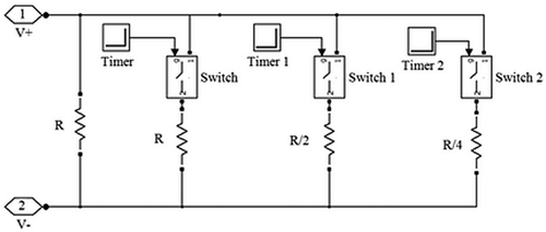
The load subsystem, displayed in an exploded view in Figure , reproduces a step time-varying dc electric load: it consists of a parallel connection of four resistors (R, R, R/2 and R/4), sequentially activated at each time step previously set before starting the simulation. Since the bus voltage is constant, the circulating current through the load will increase, when the equivalent resistance drops down, so the load power will go up too. In order to simulate a redoubling of the electric power requested by the dc-load, it was necessary to have a parallel connection between two identical equivalent resistances during each time interval. For this reason, for simulations setup, the first resistance value was set to 0.8 Ω, as well as the second one: this means that the parallel of the two resistance is a half of this value (0.4 Ω) so the load current redoubles. Hence, to redouble the electric load at the second step, the third resistance was set to R/2, or 0.4 Ω, and so on for the fourth resistor, which was set to 0.2 Ω. The idea to use four resistors rather than another number has no technical reason, because the same strategy can be followed similarly for any number of switching resistors. Except for the first resistor, which is always connected to the load subsystem terminals, each one is activated by an ideal switch (0.001 Ω internal resistance), driven by an O/I timer signal that instantaneously rises from low state (O) to high state (I) at its specified set time. Each transition time was fixed equal to a fraction of the simulation time: the first one is set to the first one is set to T/4, the second to T/2 and the third one is set to 3/4T, where T indicates the simulation time. Along these lines at each interval step, equal to a quarter of the simulation time, the total load resistance splits in a half and consequently the load power redoubles. When this load block is supplied with a dc-voltage source, owing to the fact that the employed switches are ideal with no delay time, the load voltage has no oscillations but it is permanently equal to the set value. As expected, the current through the load has a step increasing trend without any ripple; for example, for a voltage source equal to 24 V DC, the minimum current value is 30 A, that corresponds to an absorbed power of 720 W, whereas the maximum reached value is about 239 A, corresponding to a 5,736 W load.
The electric power absorbed by the load is defined by Equation (5):(5)
(5)
where R and Iload are respectively the equivalent resistance and the electric current absorbed by load.
2.5. Power management strategy
This subsystem is the logic core of the whole system model, designated to the management of energy flows through the different devices, which is addressed to maximize fuel cell efficiency and to prevent any damage possibly occurring to fuel cell and battery pack in particular. An efficient management logic must consider input and output quantities, considering the wanted relationships between them, according to control aim (Caratozzolo, Serra, & Riera, Citation2003). The control block receives as inputs fuel cell current, batteries state of charge and load current, while it provides as outputs the switch-signal for the connection/disconnection of the fuel cell and the pilot signal for PWM Generator inside DC-DC converter block. The main purpose of the designed logic control is to set the fuel cell working point at the maximum possible efficiency, using fuel cell at full power during load peaks and when battery recharging is needed. Whereas, when the batteries state of charge is greater than a threshold value, corresponding to 20%, and the load does not exceed the maximum batteries discharging current, the fuel cell provides a lower power output or it is turned off.
There will be three possible working modes for the system:
| • | both fuel cell and battery supply the load: this case occurs if SOC is included in its normal range and load current overcomes the maximum allowed battery discharging current; | ||||
| • | fuel cell supplies the load while recharging the battery pack: this second case happens when the SOC is lower than 20% and the sum of load current and battery current can be provided by the fuel cell; | ||||
| • | fuel cell does not supply electric power and battery as only power source: this last case corresponds to a normal state of charge range of batteries and a load current lower than the maximum allowed discharging value for the batteries. | ||||
In order to prevent any possible damage occurring to the fuel cell due to frequent connecting/disconnecting, the logic was designed taking into account this fact, so when the SOC overcomes 20% during the charging-mode, the fuel cell will be not disconnected instantaneously but it will continue to recharge the battery for a while. The modulating signal is determined on the basis of Table , according to equivalent load resistance and actual batteries state of charge. When the battery SOC is fixed, if the equivalent resistance R decreases, the electric power required to the fuel cell increases, then the fuel cell voltage decreases and the value of modulating signal, m, increases. When the equivalent resistance R is fixed, if the battery SOC increases, the electric power required to the fuel cell decreases, then the fuel cell voltage increases and the value of modulating signal, m, decreases.
Table 3. Modulating signals for batteries SOC < 60% (a) and for batteries SOC ≥ 60% (b) according to equivalent load resistance R
The different values were set after several simulation tries and the logic structure was developed by mean of Boolean switch blocks and Boolean compare to constant blocks. A higher value of the modulating signal corresponds to a higher power output, due to a higher PWM’s duty cycle that means less losses through the DC-DC converter.
Similarly, the fuel cell on/off signal was determined by mean of a Boolean switch block, whose Boolean switch criteria consists of a 3-way “or” condition, setting up fuel cell on-state in the case of:
| • | Iload > Ibms (80 A) | ||||
| • | SOC < SOCmin (20%) | ||||
| • | SOCmin ≤ SOC < SOCmax (80%) | ||||
If all the three conditions are false, the fuel cell command signal will be 0, then the fuel cell is disconnected from the rest of the system and battery pack acts as the only power source.
The hybrid system total efficiency, ηT, is defined by Equation (Equation6(6)
(6) ):
(6)
(6)
where is the equivalent mass flow of hydrogen requested by fuel cell to produce the positive electric power supplied by battery pack inside the hybrid system, which is defined by the Equation (7):
(7)
(7)
where is the average AEMFC electric efficiency in the battery pack charging phases.
3. Results
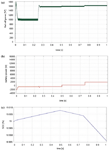
The outputs of performed simulations were obtained considering different load starting values, redoubling the load after every quarter of the simulation time, and different values of the initial batteries state of charge, whereas the operating conditions and fuel cell parameters are determined by the electric power requested by the load. Since the whole system is composed of electric devices with very short time scales, the 1 s-simulation time is enough to appreciate their fast transient and dynamic response. Both fuel cell and battery electrical power, are affected by a certain ripple, owing to dynamics, but they can be easily appreciated in terms of mean value on time. Figure shows an example of the fuel cell output power, battery power and state of charge under the following conditions: initial state of charge of 19% (so lower than its minimum threshold value) and equivalent load resistance, decreasing from 0.8 to 0.1 Ω that corresponds to a load current increasing from 24 A up to 192 A, during four time steps. During the first 0.5 s, the fuel cell is the only energy source supplying the load and the battery is in charging mode, in fact, its power is negative because the current is absorbed by the battery package and the SOC has a positive slope, just for this reason. Whereas, in the second simulation half, when the load grows till it reaches its maximum value, the fuel cell and battery are both providing power; the state of charge shows a decreasing trend with two different slopes, according to load entity and to discharging current afterwards. When the load achieves such high value the system cannot afford it without violating any borders on maximum discharging current or minimum state of charge for the batteries or maximum electric power for the fuel cell. Table summarizes a wider outline of results, considering mean values for power and voltage (affected by a slight ripple) at each time step variation, for different load sizes and two values of initial state of charge of the battery pack. The same hybrid system feeds two different electric load: a low increasing electric load with an electric resistance R equal to 12 Ω (Table (a)) and a high increasing electric load with an electric resistance R equal to 0.8 Ω (Table (b)).
Table 4. Simulations results for R values in electric load equal to 12 Ω (a) and to 0.8 Ω (b)
For a low increasing electric load, when the battery SOC percentage is under its minimum value (20%) and at 19%, the fuel cell is on, charges the battery pack and supplies the electric power requested by the electric load. In this case the electric power produced by the fuel cell is much under its maximum value. In this condition, for a low increasing electric load, when the battery SOC percentage is in the normal operative range and at 70%, the fuel cell is on but does not produce electric power, because only the battery pack can supply the electric load.
For a high increasing electric load, when the battery SOC percentage is under its minimum value (20%) and at 19%, the fuel cell is on, charges the battery pack and supplies the electric power requested by the electric load. In this case, the electric power produced by the fuel cell increases, reaching its maximum value.
For a high increasing electric load, when the battery SOC percentage is in the normal operative range and at 70%, the fuel cell is on and does not produce electric power at low values of electric load, because only the battery pack can supply the electric load, while the same fuel cell is on and produces an increasing electric power at high values of electric load, because the battery pack alone cannot supply the electric load.
According to simulations results, the hybrid energy system can afford dc loads up to 1.5 kW without any problem, irrespective of the battery state of charge. Whereas, when the SOC is included in the normal range, the system can provide over 2 kW of electric power without putting under stress the batteries, which can provide up to around 1.1 kW by themselves without any help from the fuel cell. Losses through the DC-DC converter are less for higher load value, according to the need to transfer the most possible power provided by the AEMFC. On the contrary, the fuel cell efficiency decreases when the electric load exceeds the maximum value, because of higher currents and consequent polarization phenomena. For the low increasing electric load the AEMFC electric efficiency increases, when the electric power requested to AEMFC increases and its maximum value is 0.533. In this case, the hybrid system electric efficiency is maximum at high electric load and when the battery SOC is low and only the AEMFC can work at high load and at high efficiency to supply the electric load and to charge the battery pack and the maximum value of hybrid system electric efficiency is 0.50. Also for the high increasing electric load the AEMFC electric efficiency increases, when the electric power requested to AEMFC increases and its maximum value is 0.396. Also in this case, the hybrid system electric efficiency is maximum at high electric load and when the battery SOC is low and only the AEMFC can work at high load and at high efficiency to supply the electric load and to charge the battery pack and the maximum value of hybrid system electric efficiency is 0.341. Therefore, the hybrid system defined is more efficient to supply the low increasing electric load than to supply the high increasing electric load.
4. Conclusions
The dynamic model of a hybrid AEMFC and battery hybrid system was set up and implemented in MATLAB/Simulink environment. Battery and DC-DC converter models were set up in order to reproduce real devices behavior, with a good agreement between the models data and experimental and reference model data. Simulation results show that the delay problem and the load tracking issues usually affecting fuel cell can be solved by using the hybrid system. A battery storage system, adding one more degree of freedom, solves these problems by charging or discharging, according to the load demand. A good logic control of fuel cell and battery is set up and it is the basis of the power management controller of the same hybrid system.
The model of the entire hybrid system was developed into a dynamic way and the discrete control management was designed to accommodate FC status, battery SOC and power demand in order to minimize losses during their operation; the basic principle is to use only the battery system when it can afford load requests, and to employ fuel cell system for all the remaining situations as low state of charge or high power demand. The calculation code produced in this article was used to simulate the entire managed hybrid AEMFC and battery system for two different increasing electric load and two values of initial battery pack SOC.
From the simulation results it comes to light that the fuel cell can both supply the electric load and charge the battery pack, when the SOC is less than its minimum value (20%), whereas when the electric load becomes higher and the only battery is not able to supply it, the fuel cell turns on and both the sources supply it. Converter efficiency values are very similar to their theoretical range and hybrid system have a good efficiency in all possible operating condition. In both cases, the AEMFC electric efficiency increases, when the electric power requested to AEMFC increases and the hybrid system electric efficiency is maximum at high electric load and when the battery SOC is low and only the AEMFC can work at high load and at high efficiency to supply the electric load and to charge the battery pack.
The hybrid system is more efficient to supply the low increasing electric load than to supply the high increasing electric load and its maximum efficiency is 0.5.
| Nomenclature | ||
| RL | = | resistance of inductive branch in the converter circuit (Ω) |
| L | = | inductance in the converter circuit (H) |
| RC | = | resistance of capacitive branch in the converter circuit (Ω). |
| Ron FET | = | internal mosfet resistance (Ω) |
| Rd | = | mosfet internal diode resistance (Ω) |
| RS,diode | = | diode snubber resistance (Ω) |
| CS,diode | = | diode snubber capacitance (F) |
| RS,FET | = | mosfet snubber resistance (Ω) |
| CS,FET | = | mosfet snubber capacitance (F) |
| Ron diode | = | diode resistance (Ω) |
| Vexp | = | battery voltage from experimental data (V) |
| Vmod | = | battery voltage from model output (V) |
| T | = | simulation time (s) |
| SOC | = | battery state of charge (–) |
| SOCmin | = | minimum battery state of charge threshold (–) |
| SOCmax | = | maximum battery state of charge threshold (–) |
| Iload | = | electric current absorbed by load (A) |
| Ibms | = | maximum battery discharging current (A) |
| R | = | load equivalent resistance (Ω) |
| E0 | = | constant voltage (V) |
| K | = | polarization resistance (Ω) |
| Q | = | maximum battery capacity (Ah) |
| it | = | extracted capacity (Ah) |
| i* | = | low frequency current dynamics (A) |
| i | = | battery current (A) |
| A | = | exponential voltage (V) |
| B | = | exponential capacity (Ah−1) |
| Rload | = | resistance in electric load (Ω) |
| Pload | = | electric power absorbed by the electric load (W) |
| Pbatt | = | electric power produced by the battery pack (W) |
| ηAEMFC | = | AEMFC electric efficiency (–) |
| PAEMFC | = | electric power produced by the AEMFC (W) |
| = | mass flow of hydrogen consumed by fuel cell (kg s−1) | |
| = | low heating value of hydrogen (J kg−1) | |
| = | mean electric efficiency of DC-DC converter (–) | |
| = | average electric power at the DC-DC converter inlet (W) | |
| = | average electric power at the DC-DC converter inlet (W) | |
| ηT | = | total efficiency of hybrid system (–) |
| = | equivalent mass flow of hydrogen requested by fuel cell to produce the battery electric power (kg s−1) | |
| = | average AEMFC electric efficiency in the battery pack charging phases (–) | |
Additional information
Funding
Notes on contributors
Petronilla Fragiacomo
Petronilla Fragiacomo is an Associate Professor in the Department of Mechanical, Energy and Management Engineering at the University of Calabria, Cosenza, Italy.
Emilio Astorino
Emilio Astorino and Giorgio Chippari are graduate students of the Department of Mechanical, Energy and Management Engineering at the University of Calabria, Cosenza, Italy.
Giuseppe De Lorenzo
Giuseppe De Lorenzo is a PhD and a Research Fellow in the Department of Mechanical, Energy and Management Engineering at the University of Calabria, Cosenza, Italy.
Walter Theodor Czarnetzki
Walter Theodor Czarnetzki is a Full Professor at University of Applied Sciences, Esslingen, Germany.
Waldemar Schneider
Waldemar Schneider is a Technical Director of the Institute for Sustainable Energy Technology and Mobility at University of Applied Sciences, Esslingen, Germany.
References
- Arges, C. G., Ramani, V., & Pintauro, P. N. (2010). Anion exchange membrane fuel cells. Electrochemical Society Interface, 19, 31–41.
- Caratozzolo, P., Serra, M., & Riera, J. (2003, October 12–16). Energy management strategies for hybrid electric vehicles. In Proceedings of IEEE International Electric Machines and Drives Conference (Vol. 1, p. 241). Madison: IEEE.
- Chao, C. H., & Shieh, J. J. (2012). A new control strategy for hybrid fuel cell-battery power systems with improved efficiency. International Journal of Hydrogen Energy, 37, 13141–13146.10.1016/j.ijhydene.2012.03.143
- Chen, P. C. (2011). The dynamics analysis and controller design for the PEM fuel cell under gas flowrate constraints. International Journal of Hydrogen Energy, 36, 3110–3122.10.1016/j.ijhydene.2010.11.106
- Choi, C. H., Yu, S., Han, I. S., Kho, B. K., Kang, D. G., Lee, H. Y., … Kim, M. (2016). Development and demonstration of PEM fuel-cell-battery hybrid system for propulsion of tourist boat. International Journal of Hydrogen Energy, 41, 3591–3599.10.1016/j.ijhydene.2015.12.186
- De Lorenzo, G., Andaloro, L., Sergi, F., Napoli, G., Ferraro, M., & Antonucci, V. (2014). Numerical simulation model for the preliminary design of hybrid electric city bus power train with polymer electrolyte fuel cell. International Journal of Hydrogen Energy, 39, 12934–12947. doi:10.1016/j.ijhydene.2014.05.135
- De Luca, D., Fragiacomo, P., De Lorenzo, G., Czarnetzki, W. T., & Schneider, W. (2016). Strategies for dimensioning two-wheeled fuel cell hybrid electric vehicles using numerical analysis software. Fuel Cells, 16, 628–639. doi:10.1002/fuce.201500174
- Dyer, C. K. (2002). Fuel cells for portable applications. Journal of Power Sources, 106, 31–34.10.1016/S0378-7753(01)01069-2
- El-Shater, T. F., Eskander, M. N., & El-Hagry, M. T. (2006). Energy flow and management of a hybrid wind/PV/fuel cell generation system. International Journal of Sustainable Energy, 25, 91–106.10.1080/14786450600631483
- Erickson, R.W. (1999–2014). DC-DC power converters. New York, NY: John Wiley and Sons.
- Fragiacomo, P., Astorino, E., Chippari, G., De Lorenzo, G., Czarnetzki, W. T., & Schneider, W. (2016). Anion exchange membrane fuel cell modelling. International Journal of Sustainable Energy, 19, 1–14. doi:10.1080/14786451.2016.1256887
- Gang, B. G., & Kwon, S. (2016). The proton exchange membrane fuel cell systems using methanolysis of sodium borohydride as a hydrogen source with cobalt catalysts. International Journal of Green Energy, 13, 1224–1231. doi:10.1080/15435075.2016.1183494
- Gao, L., Jiang, Z., & Dougal, R. A. (2004). An actively controlled fuel cell/battery hybrid to meet pulsed power demands. Journal of Power Sources, 130, 202–207.10.1016/j.jpowsour.2003.12.052
- Hwang, J. J., & Chang, W. R. (2012). Characteristic study on fuel cell/battery hybrid power system on a light electric vehicle. Journal of Power Sources, 207, 111–119.10.1016/j.jpowsour.2012.02.008
- Hyun, D. S., Hwang, H. J., Kim, D. U., Hwang, S., Yun, Y. H., & Oh, B. S. (2013). Development of an optimal charging algorithm of a Ni-MH battery for stationary fuel cell/battery hybrid system application. International Journal of Hydrogen Energy, 38, 9008–9015.10.1016/j.ijhydene.2013.05.063
- Kumari, S. (2011). Development of a controller for fuel cell using FPGA (Master thesis in VLSI Design & Embedded system). Department of Electronics & Communication Engineering National Institute of Technology, Rounkela Odisha.
- Merle, G., Wessling, M., & Nijmeijer, K. (2011). Anion exchange membranes for alkaline fuel cells: A review. Journal of Membrane Science, 377, 1–35.10.1016/j.memsci.2011.04.043
- Nishizawa, A., Kallo, J., Garrot, O., & Weiss-Ungethüm, J. (2013). Fuel cell and Li-ion battery direct hybridization system for aircraft applications. Journal of Power Sources, 222, 294–300.10.1016/j.jpowsour.2012.09.011
- Olgun, H., Ersoz, A., Kaya, D., Tiris, M., Akgun, F., & Ozdogan, S. (2006). Simulation Study of a PEM fuel cell system with steam reforming. International Journal of Green Energy, 1, 313–325. doi:10.1081/GE-200033613
- Pachauri, R. K., & Chauhan, Y. K. (2015). Study and performances analysis of fuel cell assisted vector control variable speed drive system used for electric vehicles. International Journal of Sustainable Energy, 36, 167–191. doi:10.1080/14786451.2015.1017495
- Padhee, S., Pati, U.C., & Mahapatra, K. (2015). Investigation on transient response of fuel cell power conditioning unit during rapid load changes. In Proceedings of IEEE International Conference on Computational Intelligence & Communication Technology. Ghaziabad: IEEE.
- Rabbani, A., Rokni, M., Hosseinzadeh, E., & Mortensen, H. H. (2014). The start-up analysis of a PEM fuel cell system in vehicles. International Journal of Green Energy, 11, 91–111. doi:10.1080/15435075.2013.769882
- San Martín, I., Ursúa, A., & Sanchis, P. (2014). Modelling of PEM fuel cell performance: Steady-state and dynamic experimental validation. Energies, 7, 670–700.10.3390/en7020670
- Shepherd, C. M. (1965). Design of primary and secondary cells-Part 2. An equation describing battery discharge. Journal of The Electrochemical Society, 112, 657–664.10.1149/1.2423659
- Smitha, B., Sridhar, S., & Khan, A. A. (2005). Solid polymer electrolyte membranes for fuel cell applications—A review. Journal of Membrane Science, 259, 10–26.10.1016/j.memsci.2005.01.035
- Suhn, K. W., & Stefanopoulou, A. G. (2005). Coordination of converter and fuel cell controllers. International Journal of Energy Research, 29, 1167–1189.
- Thounthong, P., Raël, S., & Davat, B. (2009). Energy management of fuel cell/battery/supercapacitor hybrid power source for vehicle applications. Journal of Power Sources, 193, 376–385.10.1016/j.jpowsour.2008.12.120
- Tremblay, O., Dessaint, L.A., & Dekkiche, A.I. (2007, September, 9–12). A generic battery model for the dynamic simulation of hybrid electric vehicles. In Proceedings of Vehicle Power and Propulsion Conference (VPPC) 2007 (pp. 284–289). Arlington, TX: IEEE.10.1109/VPPC.2007.4544139
- Ünlü, M., Zhou, J., & Kohl, P. A. (2009). Hybrid anion and proton exchange membrane fuel cells. The Journal of Physical Chemistry C, 113, 11416–11423.10.1021/jp903252u
- Van Dijk, E., Spruijt, H.J.N., O’Sullivan, D.M., & Klaassens, J.B. (1995). PWM-switch modeling of DC-DC converters. IEEE Transactions on Power Electronics, 10, 659–665.
- Wang, Y., Chen, K., Mishler, J., Chan, C. S., & Cordobes, A. X. (2011). A review of polymer electrolyte membrane fuel cells: Technology, applications, and needs on fundamental research. Applied Energy, 88, 981–1007.
- Wang, Y. X., Ou, K., & Kim, Y. B. (2015). Modeling and experimental validation of hybrid proton exchange membrane fuel cell/battery system for power management control. International Journal of Hydrogen Energy, 40, 11713–11721.10.1016/j.ijhydene.2015.03.073
- Wee, J. H. (2007). Applications of proton exchange membrane fuel cell systems. Renewable & Sustainable Energy Reviews, 11, 1720–1738.10.1016/j.rser.2006.01.005

