
Abstract
The main challenge of implementing and constructing a new tunnel is to monitor and mitigate ground surface disturbances that may affect existing structures. This paper analyses the soil deformations induced by tunnelling under an existing tunnel and the effect of these deformations on the existing tunnel. Both field data and numerical modelling are included in this study. Numerical modelling based on the finite element method is established to simulate the tunnelling process and the technique used in the shield machine. The model is applied to the case study of the intersection between metro line 3 tunnel underneath the existing main sewage tunnel in Cairo. Settlement of the existing tunnel and the ground surface associated with the new excavation of the new metro line 3 tunnel are monitored. The numerical model is verified with the records from the field data and then used to conduct a comprehensive parametric study to investigate the effect of tunnel orientation angle, clear distance between tunnels, soil properties, and grouting around the tunnels, on ground deformation. The analysis considers the nonlinearity of the soil, the construction stages, the grouting around the tunnel, and the shield operating parameters. Findings quantify the importance of the studied parameters on the deformation and stresses of the existing tunnel and indicate that soil-grouting is the primary parameter that controls the deformations. Also, the significant effect of the studied parameters occurs within length equal from three to four times the new tunnel diameter from the intersection point.
PUBLIC INTEREST STATEMENT
Ground deformations are critical since it is the main parameter for the impact assessment of the tunnelling process on adjacent structures. This work aims to find the most appropriate ways to reduce destructive impacts on neighbouring facilities; analyze and propose a mitigation procedure during tunnelling beneath the existing tunnel. To that aim, numerical modelling is used to simulate the interaction between the crossing tunnels. Real measurements from the case study of the intersection between Metro line 3 tunnel underneath the main sewage tunnel in Cairo are used to validate the numerical model. The research is contributed to a better understanding of the key parameters that affect the soil deformation like orientation angle, grout properties, the vertical distance between tunnels and other factors related to the tunnelling machine. In global, it will help the designer to use the appropriate parameters’ values in the design of new intersected tunnels in the future.
1. Introduction
In urban cities, the underground tunnel system is one of the essential parts of city traffic strategy. Since Cairo is considered to be one of the congested cities in the world, more underground tunnels are being planned or constructed to ease crowded traffic systems such as the El-Azhar road and the Greater Cairo metro tunnels (El-Nahhas, Citation1999, Citation1986; El-Shourbagy, Citation2016). Nonetheless, construction of a new tunnel in dense underground space faced with underground existing infrastructures and facilities, such as sewer pipelines and tunnels. Thus, the response of such existing structures is questionable, especially existing tunnels which is the concern of this paper. The prediction of ground movements and interactions of the existing tunnels is essential to maintain tunnelling operation. This prediction is significant, especially in shallow or major tunnels excavated in soft soils like clay or sandy soil, where the cost of remedial measures is very high and, in some cases, not acceptable (Bousbia & Messast, Citation2015; Ding et al., 2017; La et al., Citation2018; Sadjadi & Khalkhali, Citation2018; Shabna & Sankar, Citation2016).
Effect of the construction of a new tunnel on existing structures has been examined using different approaches: analytical method (Al-Omari et al., Citation2019; He et al., Citation2019), numerical modelling (Bilotta et al., Citation2017, Do et al., Citation2014; Huo et al., Citation2019; Li et al., Citation2020; Lin et al., Citation2019; Nematollahi & Diasb, Citation2020, Shi et al., Citation2018), in-situ field record (Mooney et al., Citation2016; Ng et Citation2004; Standing et al., Citation2015; Zhang et al., Citation2019), and physical model (Liang et al., Citation2016; Gue et al., Citation2017). Liang et al. (Citation2016) studied the effect of above-crossing tunnelling on an existing tunnel using a simplified analytical method. The tunnel was considered as a continuous Euler-Bernoulli beam with a specific equivalent bending stiffness. Three well-documented case histories were used to validate the applicability of the method, and a reasonable agreement between the predictions and observations was noticed. Though the analytical approach provides a good insight into the problem, it may not be applicable for complex tunnel interaction.
A two-dimensional (2-D) finite element was used in tunnel analysis (Chapman et al., Citation2002; Addenbrooke & Potts, Citation2001). Mazek and Almannaei (Citation2013) investigated the behaviour of the Metro tunnel line 3 using a 2-D finite element model with the COSMOS/M program. They adopted an elastoplastic constitutive model to represent the soil behaviour surrounding the tunnel. They concluded that the minimum width of the 2-D numerical model should be 10 times the metro tunnel diameter and that the ground loss is an essential parameter in tunnel performance. Although the 2-D model provides useful results, it suffers from some drawbacks. In 2-D modelling, no information provided on the tunnel head specifically of the surrounding ground as the tunnel face advances in (Liu et al., Citation2009). Also, the 2-D model cannot be used to study the interaction of crossing tunnels in the three dimensions (3-D). This prompted many researchers to conduct 3-D models to study the mutual interaction of crossing-tunnels.
Mayoral et al. (Citation2013) studied the static behaviour of the intersection of two tunnel metro lines in Mexico City. A 3-D finite-difference model was developed to simulate the construction sequence. They computed the horizontal and vertical movements in the soil due to the tunnel excavation and concluded that the computed displacements do not affect the existing tunnel. Talebinejad et al. (Citation2014) investigated the crossing Tohid twin tunnels and Line 7 beneath Line 4 in Tehran. The study analysed the effect of new tunnel construction on other tunnels and surface settlement using a full 3D numerical technique with elastic-plastic material models. It was concluded that there is considerable interaction between tunnels that require preventive measures to sustain a stable tunnelling operation. Nematollahi and Diasb (Citation2020) developed a 3-D numerical analysis using finite difference, Flac3D program, to investigate the interaction between twin tunnels and underground parking in Shiraz, Iran. The twin tunnels were excavated using Earth Pressure Balance (EPB)–Tunnel Boring Machine (TBM). Soil movement and structural forces were studied, and it was concluded that the construction sequence of underground structures has a significant effect on the soil and structure performance. Gue et al. (Citation2017) investigated the response of an existing tunnel at a different clear distance to new tunnelling using a series of centrifuge model tests. Detailed monitoring of soil surface settlements and tunnelling-induced strains in the existing tunnel lining was carried out. They concluded that, in such complex tunnelling, field data and centrifuge modelling provides useful insights to the deformation mechanism.
The effect of the intersection angle between new and existing tunnels has been studied in past researches (Chakeri et al., Citation2011; La et al., Citation2018; Ng et al., Citation2004). Avgerinos et al. (Citation2017) investigated the influence of excavation of new Crossrail tunnel perpendicularly beneath the existing central line at the northern side of Hayd park area in London using 3-D finite element method. The study revealed that the new tunnel adversely affects the hoop force, bending moment, and cross-section deformation of the existing tunnel. Also, the most critical effect was identified when the new tunnel excavation face is directly below the existing tunnel. Lin et al. (Citation2019) studied the effect of shield tunnelling of new twin Metro line 2 tunnels obliquely under crossing the existing twin Metro line 4 tunnels in Changsha City, China. A 3-D finite element was established and verified against measured field results. Existing tunnel deformation and ground movement were investigated due to excavation of the new tunnel. It was presented that ground settlement is trough above the existing tunnel as the shield machines advance due to disturbance of the first line excavation. The intersection angle was studied using a simplified model. They concluded that the maximum settlement induced in the parallel case is higher than that calculated for the perpendicular case by about 28%. Also, a sharp reduction in settlement of the existing tunnel was noticed for intersection angle from (30–60°).
The literature reviewed above reveals that both analytical and 2-D modelling is appropriate to simulate crossing-tunnels in limited cases and configuration of the tunnels. On the contrary, 3-D modelling of tunnelling intersection became a comprehensive tool to study the effects of tunnelling beneath existing structures. However, limited researches have been reported for studying the interaction of crossing tunnels at different angles on the same study. Also, grout injection around the existing tunnel was not completely covered in tunnelling interaction studies. Moreover, no highlight noticed for the simulation process of the pressurised TBM and its effect on the model parameters on the existing tunnel due to shield tunnelling.
This paper aims to investigate the effect of tunnelling beneath an existing tunnel on ground deformation using 3-D finite element model MIDAS GTS-NX 2015. The case of the crossing of Metro Line 3 beneath an existing sewer tunnel in Cairo was considered. The goals of this study are:
Establish a complete 3-D finite model for the crossing tunnels, including soil between tunnels, injected grout, TBM shield parameters, and construction sequence in the analysis.
Validate the deformation results of the proposed 3-D model with the corresponding field data records
Conduct a detailed parametric study showing the effect of different parameters on the behaviour of the crossing tunnels. These parameters will include, for example, crossing tunnels orientation, clear distance between tunnels, soil treatment around the existing tunnel, properties of the grouted soil and shield machine parameters
2. Case study
2.1. Project overview
Metro line 3 has been constructed under the existing sewer tunnel at Bab El Shaaria Square in Cairo. shows the location and cross-sections of the tunnels, while presents the plan of the two tunnels with a crossing angle of 22° on the horizontal projection. The existing sewer tunnel is built from reinforced concrete segments of 22.5 cm thick and 80 cm wide. The tunnel has additional secondary lining from the acid resistance blue bricks of 25 cm thick to guard against the aggressive nature of the wastewater and the generated hydrogen sulfide. summarises the technical specification of the sewer tunnel. The Metro tunnel has an excavation diameter equal to 9.45 m with an external lining diameter of 9.15 m and a thickness of 400 mm. The shield machine used in the excavation of Line 3 is one of the machines used before for Line 2 that completed in 1995. list the detailed technical specifications of the slurry parameters of the used shield machine and the working parameters of the TBM. The depth of the Metro tunnel at the crossing is ranged from 27.36 to 28.9 m. The thickness of the soil layer between the two tunnels is ranged from 3.3 to 3.7 m in medium dense to very dense silty poorly graded with gravel lenses.
Figure 1. Location and cross-section of the metro line 3 and sewer tunnel
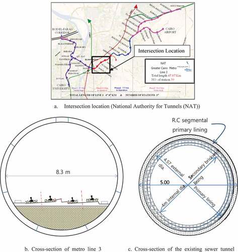
Figure 2. Crossing layout of metro line 3 tunnel and the existing Sewer tunnel
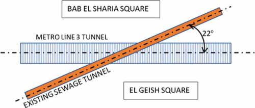
Table 1. Sewer tunnel description at the crossing location
Table 2. Slurry parameters for the used shield machine
Table 3. TBM working parameters
2.2. Geological condition
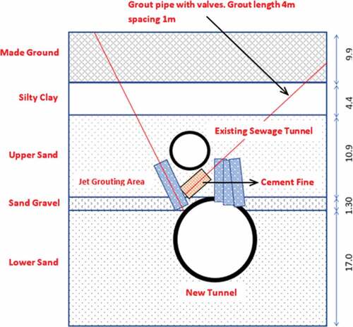
A series of boreholes were constructed along the tunnel alignment to investigate the geological conditions of the soil. According to the geological investigation, the soil profile at the crossing location consists of 9.0 m of made ground (backfill), 4.6 m of silty clay,10.8 m of the upper sand layer (medium dense to very dense silty poorly graded with gravelly lenses), 1.4 m of sand & gravel (very dense with possible clay fraction as an encounter on the first drive), and lower sand layer (very dense silty slightly gravelly poorly graded sand). Also, the water level is located at 3.1 m below the ground surface. The soil parameters are summarised in . The excavation for the metro line 3 was made within the lower sand formation, where the sand and gravel formation is on the upper part. The ground between the TBM tunnel and the sewer tunnel is within the upper sand formation.
Table 4. Soil design parameters at tunnel crossing
Before the TBM passage, a soil injection treatment was undertaken to minimise the impact on the existing sewer tunnel by reducing the soil movements and settlements. The soil treatment zone was extended 20 m along with the Sewer on each side of the crossing point. The arrangement of the soil grouting for the confined layer between the two tunnels within the crossing distance is shown in . The injected soil-grout was made from Bentonite, fine cement, water, and plasticiser. The grout was applied through injection pressure ranged from 32 to 57 bar. The parameters of the treated soil are listed in .
Figure 3. Soil treatment underneath the sewer tunnel area at the intersection location
2.3. Feild monitoring
A series of calibrated instrumentation systems were established to monitor the ground movements along with the advance of the tunnelling machine. These monitoring systems were used to predict the response of existing buildings or infrastructure under tunnel advance and give the protection measures required to avoid the failure of these structures by knowing the adequacy of each structure to sustain a specific limit of soil movements or to suggest and implement support measures to prevent the disturbance around them. Different types of instrumentation devices were used for the monitoring of soil movements around the tunnel, including settlement surface points, inclinometers to measure horizontal displacement and extensometers to measure the vertical displacement. The location of the measurement instruments and frequency of reading are detailed in the dilapidation survey report of the project issued by Cairo Metro Line 3.
3. Computational modelling
3.1. Finite element model
Different numerical methods have been used in modelling underground tunnels, of these methods, finite element, finite difference, and hybrid method. In this study, MIDAS/GTSNX (v.1.0.0) (Citation2014), which is based on finite element, was used for modelling the tunnels and the soil. The designed main tunnel lining is composed of semi-articulated rings made of seven precast reinforced concrete segments plus one key with a segment width of 1.5 m. The reduction of flexural stiffness due to the longitudinal and transversal joints is taken into account by a global approach based on Muir-Wood theory; thus, after application of the cubic root of the Muir-Wood 1975, the inertia reduction ratio to typical lining section thickness. The value of the segmental lining thickness was taken 340 mm of the nominal segment thickness of 400 mm for the Cairo Metro Tunnel. Consequently, tunnel lining is modelled as a continuous with reduced thickness to simulate the existing tunnel joints.
The soil treatment by grout targeted the soil layers between the two tunnels with a thickness ranged from 5.2 to 5.5 m. The injected soil-grout was made from Bentonite, fine cement, water, and plasticiser. The grout was applied through injection pressure ranged from 32 to 57 bar. Lower pressure was used in order not to disturb preexisting ground structure.
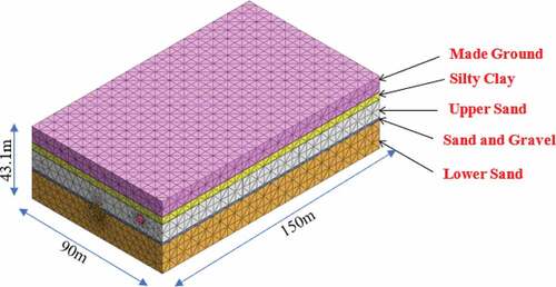
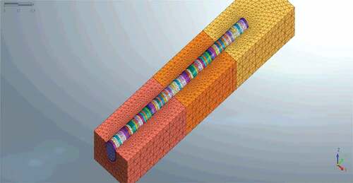
The dimensions of the overall model in X, Y, and Z directions are 150 x90x43 m, respectively, as indicated in Model dimensions were selected to predict the final settlement after the shield passes the crossing location by 100 m. The ground was assumed to consist of five layers of soil; the upper layer is made ground, silty clay, upper sand layer, sand gravel, and lower sand, in addition to the modelling of the grouted layer between the two tunnels. Solid elements were chosen for ground, tunnel, grout, and isolation. The most critical part of mesh generation is the node connection between adjacent elements so that Hybrid mesh is formed by combining a pyramid and tetrahedron on the hexahedron base was generated. MIDAS/GTSNX is capable of constraining the model automatically. Nodal DOF along the vertical sides of the model was constrained in the X direction, while for the front and back, it was constrained in the Y direction. For the nodes located at the bottom, the DOFs of Z-direction were constrained with Y and X directions. The DOFs on the ground surface were not constrained.
Figure 4. 3D Model dimension of soil and the two crossing tunnels
The soil behaviour is described using the non-associated Mohr-Coulomb (MC) criteria due to its simplicity and accuracy. The soil parameters that are considered in the model are reviewed in . The elastic material properties of the concrete lining and the grouting are shown in .
Table 5. Material properties of concrete, shield & grout
The analysis of the tunnel crossing was modelled for the soil layers and additional constraint for the grouted volume beneath the sewer tunnel. The soil-treated zone was modelled in the 3-D FEM by elastic elements with Young’s modulus of 260 MPa based on tests. Also, the grouted area was modolled to simulate as much as possible to the soil treated zone.
3.2. Loading sequence
Two types of loads were considered in the analysis: the instantaneous loads and the temporary loads. The first is the traffic load and self-weight, where the traffic load was considered 18 kN/m2 which represents an average surcharge traffic load calculated based on the Egyptian standard . The second is the construction loads for the tunnel shield during the excavation process, which includes face, jacking, contraction, and grout pressure. The weight of the water inside the sewer tunnel was considered as a dead load of the sewer tunnel. Tunnel face pressure, act normal the excavated soil, was calculated based on a coefficient of earth pressure Ko = 1-sin (φ) where φ = 20° (resulted from the disturbance of soil). Grouting pressure usually acts around the tunnel toward the soil.
The stage by stage analysis was employed to simulate the advance of TBM and the tunnel construction process. The tunnel is divided into 34 rings constructed in 43 stages. The length of the shield is 9.0 m simulated in the model as rings of width 1.5 m each. Face pressure was applied to the excavated soil at the shield face. The jacking force was rested on the tunnel segment to push the machine in advance. The soft grout was pumped from the shield tail by grouting pressure toward the soil to prevent the collapse of soil. The grout is hardened by the time in this stage, and it was assumed that the grout hardened after two rings constructed and simulated the grout pressure without taking into consideration the soft grout state. show the 3-D model simulation of analytical stages of tunnelling by a mixed shield machine.
Figure 5. Simulation of analytical stages of tunnelling by mixed shield machine
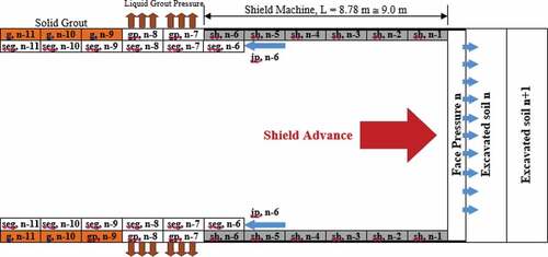
Figure 6. Simulation of shield excavation stages for the numerical model
Detailed shield operating parameters were recorded for the tunnel rout within the crossing distance to check the potential impact on the existing sewer tunnel. The recorded parameters include thrust force, shield bubble pressure, advance speed, slurry top pressure, and tail grout volume and pressure within the tunnel route. The average thrust force 26,188 kN, which less than 50% of the installed shield jacks’ power (55,800 kN). The recorded volume of tail void grout is 70% higher than the theoretical void volume. This indicates that the grout penetrates the sand soil layer around the tunnel and may lead to reducing the permeability of the sandy soil layer to a minimum and protects the tunnel from the groundwater infiltration. The average grout pressure applied is 9 bar. TBM-recorded jacking force, slurry, and grout pressures were utilised in the 3-D computational modelling to simulate the tunnelling procedure at all construction stages.
3.3. Model validation
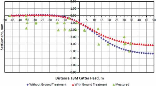
The model was validated by comparing analysis deformation results with the measured field data for both vertical and horizontal deformation. The model settlement was calculated for the case with and without soil treatment around the existing sewer tunnel. illustrates a comparison of measured and modelled vertical ground surface deformation. The measured data is recorded at 1.5 m from the ground surface. The zero distance represents the arrival of the TBM face at the monitoring point. The maximum calculated surface settlement is 4.0 mm to 5.5 mm for the case of soil treatment and without soil treatment, while the measured value is 5 mm, which is higher than the calculated maximum values by 25%. The average values of the scattered measured settlement are in good agreement with the model results. Also, soil begins to deform at a distance of 15 m before monitoring plan and steadily increased until TBM moves 30 m ahead. At 20 m, after the monitoring plan, the rate of settlement started to reduce. These remarks on the vertical settlement are in line with those of Moony et al. (Citation2016).
Figure 7. Comparison between model results and measured data for vertical deformation
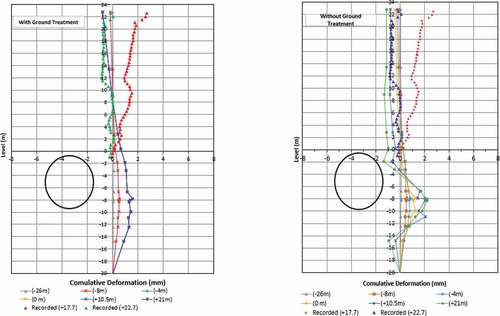
presents the variation of the horizontal deformation in the transversal direction with relation to the location of the shield cutter head and compared with the field measurements both soil treatment and without soil treatment around the Sewer tunnel. The measured transversal displacement ranges from 2 mm to 3 mm away from the shield then moves in the opposite direction to minimise the final horizontal movement. The results indicate that the numerical model can be fairly matched to the measured deformations.
Figure 8. Comparison between model results and measured data for transversal deformation
4. Parametric analysis
A series of parametric studies were performed using the verified 3-D model to develop a comprehensive understanding of the impact of tunnelling beneath an existing tunnel on the ground deformation. These parameters include:
The perpendicular orientation of the crossing tunnels;
The apparent distance between the crossing tunnels, pillar or Cr (Cr = 0.7 D and 1.5 D); where Cr is the clear vertical distance between the two tunnels at the crossing point;
The improvement of soil around the existing tunnel;
The properties of the grouted soil around the existing tunnel, Young’s Modulus of treated soil;
Applied face pressure by the shield machine;
Influence of the advancing shield distance on the existing tunnel.
4.1. Tunnels orientation angle
In order to explore the effect of the orientation angle, 3-D models with various angles were developed. The angle was changed from 22° (oblique) to 90o (perpendicular). shows the variation in the maximum settlement at the crossing point of the two tunnels. The maximum settlement was reached after the advance of the shield by 2.5D (D is the diameter of the current tunnel) from the cross-section point for the perpendicular case, while it is expanded to 4D for the oblique angle case (22°) suggesting that the smaller cross-section angle provides a broader contact distance and more settlement. Reducing the angle of intersection lead to an increase in settlement of about 33% for the ground without treatment.
Figure 9. Settlements at the crossing points of two crossing tunnels at different angles
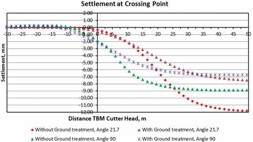
summarises the results of the settlement for different crossing angles. reveals that increasing intersection angle from 22° to 67° was followed by a 20% decrease in the settlement. However, no significant variation observed in the settlement when increasing the angle from 67° to 90°, which attributed to the wider interaction distance occurs in the small intersection angles.
Figure 10. The relation between the crossing angle and maximum settlement at the crossing point
Table 6. The maximum settlement at the crossing point for various crossing angles, φ
4.2. Clearance distance
illustrates the relative distance between the new and existing tunnel. The distance Cr or pillar is the apparent vertical distance between the external diameters of the two crossing tunnels. Two clearance distances were examined, including C = 0.7D and 1.5D, where D is the existing tunnel diameter. illustrates the variation of the maximum settlement of the existing tunnel with the clearance distances at the crossing point of the two tunnels. It is shown that for the two cases of clearance, the ground heave or the upward movement of the soil is minimal until the shield reaches the crossing point and that heave can be ignored. Also, the displacements decrease smoothly with the increase of the clearance distances however the decreasing trend is not rapid, as it decreased by only 30% of the maximum settlement when the clearance distance doubled from 0.7D to 1.5D.
Figure 11. The vertical clearance, C between the two crossed tunnels (C is related to the existing tunnel; 1.5D = 7.5 m)
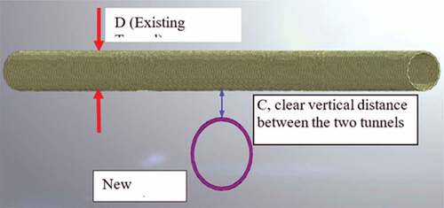
Figure 12. The maximum settlements at the crossing point of the two crossing tunnels at different clearance distances
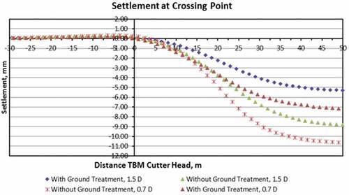
Moreover, the effective distance for maximum settlement of an existing tunnel to occur is 3.5D for more significant clearance to 4.5D for smaller clearance, which determines the most significant influencing zone of the crossing distance. Besides, increasing of clearance distance maybe not the most effective way to reduce the disturbance of tunnel crossing in practice but needs additional measures to be taken.
4.3. Soil treatment
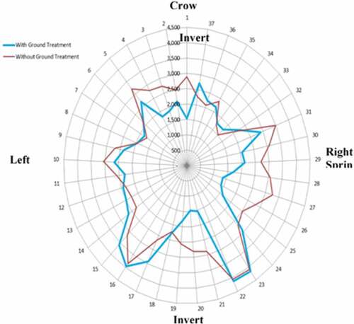
Effect of soil improvement on the performance of the existing tunnel was studied. The tunnels were analysed considering ground treatment and without ground treatment, and the performance of lining of the existing tunnel was investigated. (ac) compares the principal stresses (ơ1, ơ2, and ơ3) of the existing tunnel at the crossing point with the new tunnel. Also, illustrates the variation of Von-Mises stress ơv in the existing tunnel lining. It can be seen that ground treatment reduces the lining stresses by 20% at the crown and invert of the tunnel.
Figure 13. Variation of principal stresses (σ1, σ2, σ2) in the existing tunnel lining
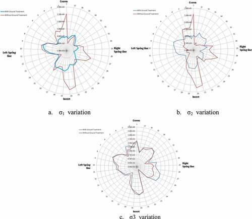
Figure 14. Von-Mises stresses in the existing tunnel lining
Also, settlement of the existing tunnel was examined against soil treatment. The achievement of the soil grouting is the reduction of settlements by a percentage ranging from 25% to 35% and, therefore, reduce the adverse actions on the existing tunnel structure. It could be concluded that the soil-grout around the existing tunnel plays the leading role in the reduction of tunnelling effects on the existing tunnel and with the assistance of the other parameters as control of face pressure, proper sizing and selection of grout material; tail grout pressure can minimise the disturbance and effects on the existing tunnel to a minimum.
4.4. Properties of grouted soil
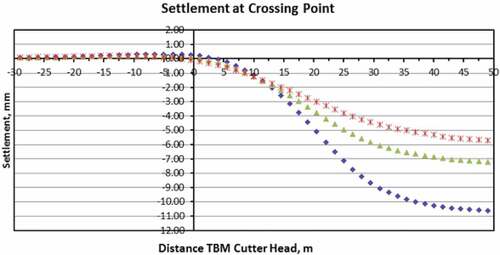
The impact of grouting properties on the existing tunnel settlement was studied by the variation of the Young’s modulus E of the grouted soil around the existing tunnel. Two values were included in the analysis; 260 MPa, and 410 MPa. presents the variation of the maximum settlement at the crossing point with Young’s modulus values. As can be seen, increasing of Young’s modulus from 260MPa to 410 MPa leads to a reduction of 20% in the maximum settlement at the crossing point. Also, comparing the results of the settlement with the case of no treatment reveals that the reduction of the maximum settlement is 45% for a higher quality of soil treatment and 31% for lower quality of soil treatment. Moreover, it can be observed that the maximum settlement occurs after the shield passed the crossing point by 5D, in the case of soil without treatment, and 4D for the case of soil treatment around the existing tunnel. This indicates that use grouting with high strength reduces the affected settlement zone area.
Figure 15. Settlements at the crossing points with different characteristics of treated soil
4.5. Applied face pressure by the shield machine
Pressurised-face TBMs, such as Mixed Shield Machines, are essential to control ground deformation. Pressurized-face generates support pressures at the tunnel face (face pressure), along with the shield skin (annulus pressure) and behind the shield tail outside the lining segments (grout pressure) play a significant role in limiting ground deformation. The applied support pressures act against the total earth pressure (vertical and horizontal effective stress and hydrostatic pore water pressure) along the TBM and tunnel boundary. The changes in effective stress induce ground deformations. Changes in effective stress during TBM tunnelling result from vertical and lateral stress release, soil arching, and hydraulic gradients created if groundwater is allowed to flow into the tunnel face. Ground surface settlement and movements are usually related to volume loss at the TBM. The minimisation of the volume loss needs the applying of proper face pressure during the tunnelling process. Proper design and operation of the shield machine can reduce volume loss to less than 50% of the theoretical values.
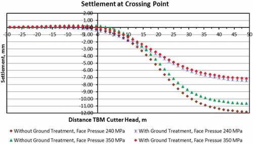
displays the variation of the model applied face pressure on the maximum settlement at the crossing point. The results indicate that the increase in applied face pressure leads to smaller settlements. Also, the importance of the increased face pressure decreases with the soil-grout around the existing tunnel. Moreover, the settlement decreases by 37% with the grouted soil and only 10% with the increases in face pressure. It may be concluded that the face pressure is a concern in the cases of no soil treatment around the existing tunnel.
Figure 16. Settlements at the crossing point at different face pressures with and without soil treatment
4.6. Shield advancing distance
As the shield advancing, the heave of the tunnel is started developing, and it is a typical dynamic procedure. This heave continues until the shield passes the studied point. After the shield passes this point, the vertical settlement is starting to occur and continue to propagate. The maximum settlement at the study point can be reached after the shield passes by a distance ranged from 3D to 5D depending on different parameters as the soil type treated or not treated, type of treatment, crossing angle, clearance distance, tail grout pressure, and face pressure.
The influence of the shield advance distance controls the needs for continuous monitoring of the construction process and the minimum length needed to reduce the construction risks. Also, the tunnel is nearly unaffected by the shield excavation when the shield is 3D ahead or away from the crossing point for soil-treated case and by 5D for without soil treatment case. Therefore, the crossing section from −3D to 3D, defined as influencing region for the shield tunnelling in the case of soil treatment. The tunnel displacement is relatively sensitive to the advancing of the shield and the maximum settlements of tunnel increase sharply during the crossing of the influencing region. The precise monitoring system is needed within this influence region, and more attention should be given when the shield is driven exactly in the centerline of the influencing region. Effective protective measures, such as applying proper jet grouting, should be implemented to control the settlements of the tunnel within the acceptable magnitude and within the serviceability limit.
5. Conclusions
In summary, we have performed 3D computational modelling (MIDAS/GTSNX) to investigate the ground deformation due to tunnelling beneath an existing tunnel. The MIDAS model has been validated using data from the Metro Line 3 project. The following can be drawn based on the study:
The 3D model is applicable to predict the interaction between the crossing tunnels, where the model results were consistent with the field data.
Grouting around the existing tunnel has a major impact on ground deformation, where a 38% reduction in results of the ground deformation was found in cases where grouting was used.
Smaller crossing angles result in a broader distance of contact and more settlement accordingly, where a rise of 33% in the settlement was observed compared to perpendicular tunnels.
Doubling the clear distance between tunnels resulted in only a 30% reduction of the ground settlement, which indicates that increasing the clear distance is not the most effective way to reduce the ground deformation.
Using grouting with higher strength reduces the affected settlement zone by 20% in length.
Increase the applied face pressure by the shield machine results in a reduction of 35% in the maximum settlement, but this reduction reduced to 10% only where soil treatment is employed.
The significant effect of all the above factors occurs within length equal from three to four times the new tunnel diameter from the intersection point. Therefore, this part of soil should be improved by a proper grouting method and apply monitoring system during the construction to update the simulation parameters to be used in the future works.
Notation
The following symbols are used in this paper C cohesive strength
Cu unconfined cohesive strength
Cr clearance distance
2-D two dimensional
3-D three dimensional
D tunnel diameter
DOFs degrees of freedom
E modulus of elasticity
EPB earth pressure balance
FEM finite element model
TBM unnel boring machine
φ angle of internal friction
ϕ tunnels intersection angle
ν passion’s ratio
ϒ unit weight
Ơ principal stresses
Acknowledgements
The authors acknowledge both the Greater Cairo Sanitary Drainage Company (GCSDC) and the National Authority for Tunnels (NAT) and the Egyptian Tunneling Society for their technical support. Moreover, the authors would like to express their sincere appreciation and gratitude to the staff of International European Business MIDAS Information Technology Co., Ltd.
Additional information
Funding
Notes on contributors

Nasser Z. Ahmed
Nasser Z. Ahmed is an assistant professor of civil engineering at Beni-Suef University, Egypt. His research interest is the design of steel and concrete structures, numerical modelling of structures, the stability of structures and dynamic analysis of structures.
Mohamed El-Shourbagy
Mohamed El-Shourbagy PhD graduate in civil engineering (structure) from faculty of engineering, Cairo University. His research interest is the analysis and design of infrastructures.
Adel Akl
Adel Akl is professor of structural analysis and mechanics at Cairo University, Egypt. He has a very long experience in analysis and design of the structure. Also, he is expert in soil-structure interaction researches.
Kamal Metwally
Kamal Metwally is associated professor of civil engineering at Beni-Suef University, Egypt. His research interest is the finite element of structures, structural analysis and design of infrastructures, design of concrete and steel structures.
References
- Addenbrooke, T. I., & Potts, D. M. (2001). Twin tunnel interaction: Surface and subsurface effects. International Journal of Geomechanics, 1(2), 249–19. https://doi.org/10.1061/(ASCE)1532-3641(2001)1:2(249)
- Al-Omari, R. R., Medhat, S. A., & Osamah, I. A. (2019). Effect of tunnel progress on the settlement of existing piled foundation”. Studia Geotechnica Et Mechanica, 41(2), 102–113. https://doi.org/10.2478/sgem-2019-0008
- Avgerinos, V., Potts, D. M., & Standing, J. R. (2017). Numerical investigation of the effects of tunnelling on existing tunnels. Géotechnique, 67(9), 808–822. https://doi.org/10.1680/jgeot.SiP17.P.103
- Bilotta, E., Paolillo, A., Russo, G., & Aversa, S. (2017). Displacements induced by tunnelling under a historical building. Tunnelling and Underground Space Technology, 61, 221–232. https://doi.org/10.1016/j.tust.2016.10.007
- Bousbia, N., & Messast, S. (2015). Numerical modelling of two parallel tunnels interaction using three dimensional finite elements method. Geomechanics and Engineering, 9(6), 775–791. https://doi.org/10.12989/gae.2015.9.6.775
- Chakeri, H., Hasanpour, R., Hindistan, M. A., & Ünver, B. (2011). Analysis of interaction between tunnels in soft ground by 3D numerical modelling. Bulletin of Engineering Geology and the Environment, 70(3), 439–448. https://doi.org/10.1007/s10064-010-0333-8
- Chapman, D. N., Rogers, C. D. F., & Hunt, D. V. L. (2002). Prediction of settlement above closely spaced multiple tunnel constructions in soft ground. Proceedings of the Third International Symposium on the Geotechnical Aspects of Underground Construction in Soft Ground, 299–300.
- Dilapidation Report for CWO crossing. (2010). 160-G2-JVC-004-N-005-A, issued by Cairo metro line 3 joint venture g2 for civil works.
- Do, N. A., Dias, D., Oreste, P., & Djeran-Maigre, I. (2014). 2D numerical investigations of twin tunnel interaction. Geomechanics and Engineering, 6(3), 263–275. https://doi.org/10.12989/gae.2014.6.3.000
- El-Nahhas, F. M. (1986). Spatial mode of ground subsidence above advancing shielded tunnels. Proceeding of the International Congress on Large Underground Opening, Firenze, Italy, 1, 720–725.
- El-Nahhas, F. M. (1999). Soft ground tunnelling in Egypt. Geotechnical challenges and expectations. Tunnelling and Underground Space Technology, 14(3), 245–256. https://doi.org/10.1016/S0886-7798(99)00041-3
- El-Shourbagy, M. A. (2016). Numerical simulation of shield tunneling, with special application on tunnels crossing in Cairo [PhD. Thesis]. Department of Structural Engineering, Faculty of Engineering, Cairo University.
- Gue, C. Y., Wilcock, M. J., Alhaddad, M. M., Elshafie, M. Z., Soga, K., & Mair, R. J. (2017). Tunnelling close beneath an existing tunnelling clay – Perpendicular undercrossing. Géotechnique, 67(9), 795–807. https://doi.org/10.1680/jgeot.SiP17.P.117
- He, C., Zhou, S., Di, H., & Yang, X. (2019). Effect of Dynamic Interaction of Two Neighboring Tunnels on Vibrations from Underground Railways in the Saturated Soil. KSCE Journal of Civil Engineering, 23(11), 4651-4661. DOI: 10.1007/s12205-019-0084-4
- Huo, R., Zhou, P., Song, Z., Wang, J., Li, S., & Zhang, Y. (2019). Study on the settlement of large-span metro station’s baseplate caused by the tunnels newly built beneath it. Advances in Mechanical Engineering, 11(2), 2. https://doi.org/10.1177/1687814018825161
- La, Y. S., Kim, B., Jang, Y. S., & Choi, W. H. (2018). Stress interactions between two asymmetric noncircular tunnels. Geomechanics and Engineering, 15(3), 869–877. https://doi.org/10.12989/gae.2018.15.3.869
- Li, P., Lu, Y., Lai, J., Liu, H., & Wang, K. (2020). A comparative study of protective schemes for shield tunnelling adjacent to pile groups. Advances in Civil Engineering, 2020, 1-16. https://doi.org/10.1155/2020/6964314
- Liang, R., Xia, T., Hong, Y., & Yu, F. (2016). Effects of above-crossing tunnelling on the existing shield tunnels. Tunnelling and Underground Space Technology, 58, 159–176. https://doi.org/10.1016/j.tust.2016.05.002
- Lin, X. T., Chen, R. P., Wu, H. N., & Cheng, H. Z. (2019). Deformation behaviours of existing tunnels caused by shield tunnelling undercrossing with oblique angle. Tunnelling and Underground Space Technology, 89, 78–90. https://doi.org/10.1016/j.tust.2019.03.021
- Liu, H. Y., Small, J. C., Carter, J. P., & Williams, D. J. (2009). Effects of tunnelling on existing support systems of perpendicularly crossing tunnels. Computers and Geotechnics, Elsevier Science Ltd., 36(5), 880–894. https://doi.org/10.1016/j.compgeo.2009.01.013
- Mayoral, J. M., Roman-de la Sancha, A., Osorio, L., & Martinez, S. (2013). Numerical analysis of a tunnel intersection. Proceedings of the 18th International Conference on Soil Mechanics and Geotechnical Engineering, 769–772. https://www.issmge.org/uploads/publications/1/2/769-772.pdf
- Mazek, S. A., & Almannaei, H. A. (2013). Finite element model of Cairo metro tunnel-Line performance. Ain Shams Engineering Journal, 4(4), 709–716. https://doi.org/10.1016/j.asej.2013.04.002
- MIDAS/GTSNX (v.1.0.0) (2014), manual - copyright since1989 MIDAS Information Technology Co. Ltd., http://manual.midasuser.com/en_common/GTS%20NX/100/GTX.htm
- Mooney, M. A., Grasmick, J., Kenneally, B., & Fang, Y. (2016). The role of slurry TBM parameters on ground deformation: Field results and computational modelling. Tunnelling and Underground Space Technology, 57, 257–264. https://doi.org/10.1016/j.tust.2016.01.007
- Nematollahi, M., & Diasb, D. (2020). Interaction between an underground parking and twin tunnels – Case of the Shiraz subway line. Tunneling and Underground Space Technology, 95, 103150. https://doi.org/10.1016/j.tust.2019.103150
- Ng, C. W., Boonyarak, T., & Mašín, D. (2004). Three-dimensional centrifuge and numerical modelling of the interaction between perpendicularly crossing tunnels. Canadian Geotechnical Journal, 50(9), 935–946. https://doi.org/10.1139/t04-008
- Ng, C. W. W., Lee, K. M., & Tang, D. K. W. (2004). Three-dimensional numerical investigations of new Austrian tunnelling method (NATM) twin tunnel interactions. Canadian Geotechnical Journal, 41(3), 523–529. https://doi.org/10.1139/t04-008
- Sadjadi, F., & Khalkhali, A. B. (2018). Geotechnical challenges of Tehran metro line 7 (South Northern Route). Civil Engineering Journal, 4(5), 1117–1126. https://doi.org/10.28991/cej-0309161
- Shabna, P. S., & Sankar, N. (2016). Numerical analysis of shallow tunnels in soft ground using Plaxis2D. Int J Sci Eng Res, 7(4), 161–166. https://www.ijser.org/researchpaper/NUMERICAL-ANALYSIS-OF-SHALLOW-TUNNELS-IN-SOFT-GROUND-USING-PLAXIS2D.pdf
- Shi, J., Zhang, X., Chen, Y., & Chen, L. (2018). Numerical parametric study of countermeasures to alleviate basement excavation effects on an existing tunnel. Tunnelling and Underground Space Technology, 72, 145–153. https://doi.org/10.1016/j.tust.2017.11.030
- Standing, J. R., Potts, D. M., Vollum, R., Burland, J. B., Tsiampousi, A., & Afshan, S. (2015). Investigating the effect of tunneling on existing tunnels. Underground Design and Construction Conference, IOM3 Hong Kong Branch, 301–3012.
- Talebinejad, A., Chakeri, H., & Moosavi, M. (2014). Investigation of surface and subsurface displacements due to multiple tunnels excavation in urban area. Arabian Journal of Geosciences, 7(9), 3913–3923. https://doi.org/10.1007/s12517-013-1056-5
- Zhang, N., Zhu, X., & Ren, Y. (2019). Analysis and study on crack characteristics of highway tunnel lining. Civil Engineering Journal, 5(5), 1119–1123. https://doi.org/10.28991/cej-2019-03091316