
 ?Mathematical formulae have been encoded as MathML and are displayed in this HTML version using MathJax in order to improve their display. Uncheck the box to turn MathJax off. This feature requires Javascript. Click on a formula to zoom.
Abstract
This research presents a response analysis of a UAV nose landing gear system equipped with an air damper under shock and harmonic excitation. The study begins with dynamic modeling of the UAV landing gear system. The system dynamics consists of a main mass and a wheel mass that are connected to each other by a U-shaped landing gear. The U-shaped landing gear is modeled by a linear spring and dashpot element. The air damper is added to the landing gear to increase the damping. The air damper consists of an air balloon that is connected to the outside via an orifice hole and the connecting pipe. A serial connection of spring, mass, and dashpot elements describes the air damper dynamic model. The simulation study is conducted to evaluate the effect of the landing gear parameters variation on the UAV dynamic response under shock and harmonic excitation. The maximum acceleration and displacement response of the UAV body under shock load is greatly affected by the air balloon cross-sectional area (Aef) and the stiffness of the U-shaped landing gear system (KL). The harmonic response of the UAV body is evaluated from the ratio between the UAV body displacement amplitude and the base excitation amplitude under harmonic excitation. It is shown that the air balloon cross-sectional area (Aef) and the connecting pipe length (lp) have a significant effect on the UAV mass displacement ratio. The experimental study is conducted to validate the simulation results. It is shown that the experimental data can verify the simulation results.
Keywords:
PUBLIC INTEREST STATEMENT
This research presents a concept of shock vibration attenuation for an unmanned aerial vehicle (UAV) landing gear using an air spring combined with a permanent U-shaped spring system. The air spring can increase the landing gear resistance to the shock and fatigue loads. The air spring characteristic which depends on the balloon dimensions is very useful in setting the optimal value for the landing gear stiffness. The landing gear damping comes from the resistance of air flowing through the orifice and connecting pipes. This research has a potential contribution to the development of shock vibration absorbers for several applications such as UAV landing gear systems, fast boat suspension systems, and vibration dampers on bicycles and motorbikes. In general, the application of the concept of shock absorbers using air springs proposed in this study is not only limited to the engineering field but also in some fields related to the negative effects of shock vibrations on comfort and safety.
1. Introduction
An unmanned aerial vehicle (UAV) is a pilotless aircraft controlled remotely using a remote-control system or computer. Nowadays, UAV has been extensively used in several fields such as cultural heritage application (Eisenbeiss & Zhang, Citation2006), civil infrastructure inspection (Fuqaha et al., Citation2018; Tkáč & Mésároš, Citation2019), supply chain management (Carames et al., Citation2019), traffic monitoring (Puri et al., Citation2007), and vegetation monitoring (Sugiura & Ishii, Citation2005). One important component of UAV is the landing gear system. The main function of a landing gear system is to support the UAV body during ground maneuvering and reduce the shock-induced vibration that occurred during landing (Son et al., Citation2018).
Most of the UAV vibration energy during ground maneuvering and landing is absorbed by the landing gear system to ensure proper aircraft performance (Lopes & Ayala, Citation2020). The landing gears must withstand different types of vibrations when the aircraft maneuvers on the runway. Two of the most critical types of vibration are self-induced shimmy and brake-related vibration such as gear-walk. Shimmy occurs when the torsional structural dynamics is poorly damped (Orlando, Citation2020; Rahmani & Behdinan, Citation2020). The gear walk phenomenon is observed when the translational deflection amplitude in the landing gear is relatively high due to the braking force acting at the tire contact with the ground (Gualdi et al., Citation2008).
Another important vibration phenomenon in the landing gear system is shock-induced vibration. During landing, a large impulsive force is received by the UAV tire-wheel in the instant after contact with the ground. A worse designed landing gear system causes a large force transmission from the wheel to the UAV body. As a result, the UAV body vibration becomes large. This condition not only reduces the system safety and comfort but can also damage the landing gear components and UAV fuselage structure. Therefore, it is important to develop an effective landing gear system for absorbing the impact-induced vibration energy (Luo et al., Citation2019).
Several landing gear design and control methods have been proposed by many researchers to reduce the aircraft vibration amplitude during landing and ground maneuvering. Dragus et al. (Citation2019) investigated the design and analysis of low-cost and small mass landing gear systems using composite materials. Wang et al. (Citation2008) propose an active landing gear system to reduce vibrations caused by landing impacts and runway excitations. A modification of an oleo strut damper using MR fluid to change the damping coefficient has been proposed by Asthana et al. (Asthana & Bhat, Citation2012).
A magneto rheology fluid-based landing gear system has been developed to reduce the shock-induced vibration during landing (Lenggana et al., Citation2020; Zhu et al., Citation2011). A method of impact energy dissipation using a pneumatic adaptive landing gear system has been proposed by Faraj et al. (Citation2018).
Currently, Son and Huda (Citation2019) propose a landing gear system using the kinematic mechanism. The nonlinear characteristics of the force vs displacement relationship exhibit a reduction of the maximum acceleration response of the main system under shock load. However, the maximum landing gear displacement is larger in comparison with the conventional landing gear system consisting of a linear spring and dashpot element.
An oleo-strut pneumatic system has been used for landing gear by most large aircraft and many smaller ones. This landing gear consists of a pneumatic air for spring system combined with an oil hydraulic shock absorber. A comprehensive design of the oleo-pneumatic nose landing gear system was proposed by Ahmad et al. (Citation2020). A method for adaptive control of pneumatic landing gear system was investigated by Mikulowski et al. (Citation2009).
This research proposes a landing gear system for a small UAV using a U-shaped spring and an air spring-damper system. Unlike the oleo-strut pneumatic system, the proposed landing gear system does not use an oil hydraulic for the damper. The damping mechanism is obtained using a long pipe that connects the air balloon to the outside environment. This type of landing gear is lightweight; therefore, it has a small contribution to the landing gear’s total weight. To the best of the author’s knowledge, the dynamic response analysis of the landing gear system using a U-shaped spring and air damper under shock and harmonic load has not much been conducted by other researchers.
The stiffness and damping characteristics of the proposed landing gear system are evaluated by varying the air damper parameters such as cross-sectional area (Aef) and height (Hef) of the balloon, radius (rp) and length (lp) of the connecting pipe, and the losses coefficient (KT). The simulation study is conducted to evaluate the effect of air damper parameters variation on the UAV response under shock excitation during landing and harmonic excitation on the UAV wheel. The experimental study is conducted to validate the simulation results.
2. Materials and methods
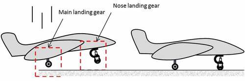
shows the UAV landing mechanism. The landing process begins when the main landing gear touches the ground and is then followed by the nose landing gear system. During ashort landing period, an impulsive load works on the wheel and induces the shock load to the landing gear. After landing, the UAV landing gear system receives runway excitation at its wheel due to road surface irregularities.
Figure 1. UAV landing process
The maximum acceleration response of the UAV body at the instant after landing should be as small as possible to obtain the safe and comfortable landing gear system. The large acceleration response not only breaks the landing gear components and UAV fuselage structure but also affects the safety of the precise electrical instrument installed inside the UAV.
The maximum landing gear displacement during landing is another factor that should be considered for designing the landing gear system. The maximum displacement response is limited by the available space in the UAV fuselage. Generally, the large landing gear stiffness can reduce the maximum landing gear displacement; however, it has a negative effect in increasing the maximum acceleration response of the UAV body during landing.
The UAV response during ground maneuvering (taxiing) is analyzed from the ratio between the UAV body displacement amplitude and the excitation amplitude (X/X0). This ratio represents the displacement transmissibility between the UAV body and road irregularities.
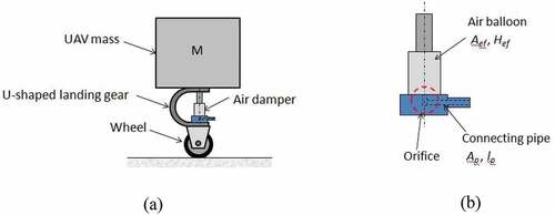
A simplified model representation of the UAV body and U-shaped nose landing gear equipped with an air damper system is shown in ). M describes the portion of UAV mass supported by the nose landing gear system. Typically, 20% of the UAV’s total mass is supported by the nose landing gear system. ) shows the components of an air damper system. The air damper system consists of an air balloon, orifice, and the connecting pipe.
Figure 2. Nose landing gear with an air damper. (a) Simplified model and (b) air damper elements
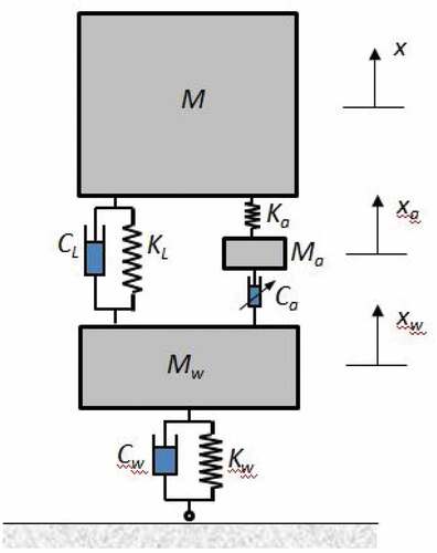
A dynamic model of the UAV nose landing gear system with an air damper is depicted in . As shown in , the U-shaped landing gear model consists of a spring, and a viscous element with the stiffness and damping coefficient are KL and CL, respectively. The air damper system is modeled by a serial connection of mass (Ma), spring (Ka), and viscous damping (Ca), respectively. Ma is related to the air mass that flows through the orifice hole and connecting pipe when the piston is compressed and expanded (Moheyeldein et al., Citation2018). The U-shaped landing gear and air damper configuration are parallel. Mw, Kw, and Cw, respectively, represent the wheel mass, stiffness, and damping.
Figure 3. The dynamic model of a landing gear system
2.1. Governing equations during landing
The governing equation of UAV nose landing gear system during landing, as shown in , is written as:
Ka, Ca, and Ma in EquationEquations (1(1)
(1) )–(Equation3
(3)
(3) ) are the air spring stiffness, the damping coefficient of the air damper, and the air mass flow inside the connecting pipe, respectively. In the case of an air balloon that is connected directly to the outside environment via a connecting pipe as used in this study, Ka, Ca, and Ma can be calculated as follows (Moheyeldein et al., Citation2018):
P0, n, Aef, and VB0 in EquationEquation (4)(4)
(4) are the absolute pressure of the air spring, the polytrophic coefficient, the effective cross-sectional area of the air balloon, and the initial volume of the balloon, respectively. ρair, Ap, lp, and KT in EquationEquations (5
(5)
(5) ) and (Equation6
(6)
(6) ) are the air density, the cross-sectional area, the length of the connecting pipe, and losses constant, respectively.
The system’s equation of motions in EquationEquations (1)(1)
(1) –(Equation3
(3)
(3) ) is nonlinear because the damping force of the air damper and the wheel contact force fw are the nonlinear functions. Ka in EquationEquation (4)
(4)
(4) describes the stiffness of the air system inside the air balloon. Ca in EquationEquation (5)
(5)
(5) describes the damping effect associated with air spring. Generally, there are two kinds of damping in the air spring system due to the flow of air between the air balloon and the outside environment. Capillary damping is due to the resistance of the air mass flow through a connecting pipe. The capillary damping value depends on the pipe length and surface roughness. The orifice damping occurs when the airflow passes through the orifice hole. The damping coefficient becomes large when the flow resistance and the ratio between the air balloon and the connecting pipe cross-sectional area are large, respectively. Ma in EquationEquation (6)
(6)
(6) is the airflow mass inside the connecting pipe due to the air balloon pressure variation during the piston stroke motion.
The contact force becomes zero when the wheel loses contact with the ground. The contact force is expressed as:
At the instant before landing, the system is assumed to be in free-fall condition with the initial velocity:
where h in EquationEquation (8)(8)
(8) is the initial elevation of the landing gear system.
2.2. Harmonic vibration of UAV
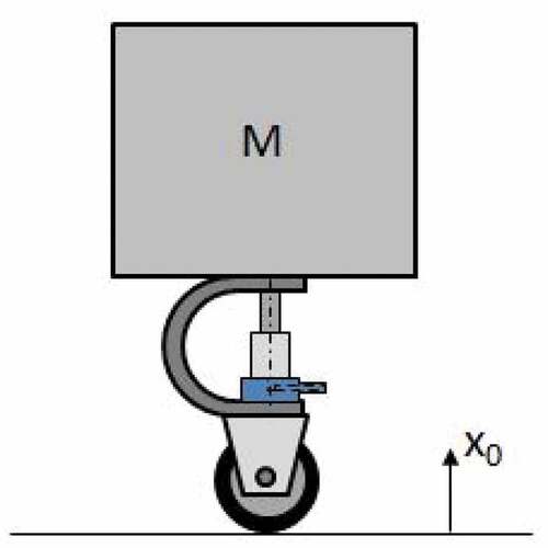
The UAV landing gear response under harmonic excitation x0 on the UAV wheel due to the road irregularities is derived using the dynamic model, as shown in . The governing equations of the UAV model under harmonic excitation are calculated as follows:
Figure 4. Landing gear system under harmonic runway excitation
where
and
EquationEquation (12)
(12)
(12) are the amplitude and frequency of the runway excitation, respectively.
2.3. Linear response calculation using modal analysis
For low frequency of vibration, the nonlinear damping force from the air damper can be approximated by a linear function
. Under this condition, the governing equation of the system dynamics can be written in the matrix form as follows:
By using the modal coordinate transformation , thus EquationEquation (13)
(13)
(13) can be expressed as:
Multiplying of EquationEquation (14)(14)
(14) with
resulting
where is the eigenvector of the system. In the case of mass-normalized eigenvector, EquationEquation (15)
(15)
(15) is simplified as:
The response of the system in modal coordinate is obtained by numerically solving Equation (16) using the initial condition and the external modal force
. The system response in the generalized coordinate is calculated as follows:
or
According to EquationEquation (17(17)
(17) ), the displacement and acceleration response of the main mass can be calculated as follows:
Subscripts 1, 2, and 3 in EquationEquations (18)(18)
(18) and (Equation19
(19)
(19) ) represent the response components for the first, second, and third modes of vibration, respectively.
3. Results and discussion
3.1. Simulation study
The simulation study is conducted to evaluate the effect of UAV landing gear parameters variation on the dynamic response during landing and ground maneuvering (taxiing) under harmonic excitation on the UAV wheel. shows the landing gear parameters used in the simulation. Most of the simulation parameters in use the measured experimental data such as: the air spring dimensions and the UAV mass. Other parameters such as the stiffness and the damping coefficient are estimated by comparing the simulation and the experimental data.
Table 1. Landing gear parameters
Several simulations are performed to analyze the effect of parameter variation on the landing gear performance in reducing the maximum acceleration and displacement of the UAV body.
3.1.1. Shock vibration response during landing
The shock vibration response of the UAV is calculated numerically from EquationEquations (1)(1)
(1) –(Equation3
(3)
(3) ) using the initial condition as depicted in EquationEquation (8)
(8)
(8) . The initial elevation of the UAV before landing is 0.07 m; thus, the initial velocity related to the free-fall condition is v0 = vw0 = 1.17 m/s. The landing gear parameters in are used as reference parameters. shows the UAV body acceleration response calculated numerically from nonlinear equations in EquationEquations (1)
(1)
(1) –(Equation3
(3)
(3) ) and ones calculated by the modal analysis technique using the approximated linear model in EquationEquations (13)
(13)
(13) –(Equation19
(19)
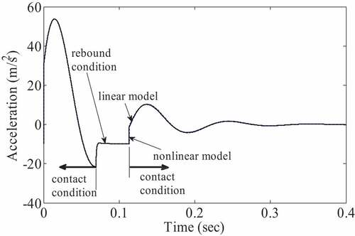
(19) ). As shown from , during the period time from 0.06–0.11 s, the landing gear system is in free flight because of a rebound motion after contacting the ground. It is shown from that the acceleration response obtained by modal analysis of linear model is similar to the calculation from the nonlinear model.
Figure 5. UAV body acceleration response calculated using a linear and nonlinear model
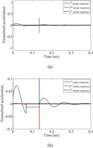
shows the response components of UAV body acceleration for each vibration mode. During the contact period, the first mode of vibration is dominant. It can be shown from that the response components in the first mode are almost the same as the total response of the UAV body as depicted in .
Figure 6. Acceleration response components of UAV body. (a) Normal scale and (b) zoom scale
Simulation study is conducted to evaluate the effect of landing gear parameter variation on the maximum acceleration and displacement response of the UAV body at the instant after landing. The nominal parameter values used in the simulation study are KL = 1 × 10⁴ N/m, CL = 75 N.s/m, Cw = 2000 N.s/m, Aef = 7 × 10⁻⁴, Hef = 0.07 m, rp = 0.001 m, lp = 0.001 m, and KT = 1.
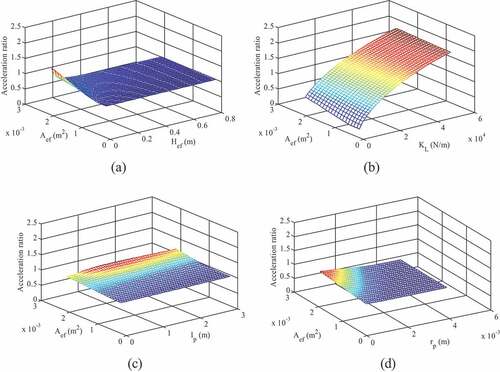
)-7(d) shows the effect of air damper parameter variation on the acceleration ratio of the UAV body after landing. The acceleration ratio is defined as the ratio between the maximum acceleration responses obtained with and without an air damper. ) shows that for the low value of Aef, the acceleration ratio is small and independent of Hef. The acceleration ratio depends on Hef when Aef is large. It can be shown from ) that for a large value of Aef, the acceleration ratio decreases as the air damper height increases. The effect of Aef and KL variations on the acceleration ratio is depicted in ). It is shown in ) that the acceleration ratio increases as KL increases. The acceleration ratio depends on KL and Aef for small KL and a large value of KL, the acceleration ratio is independent of Aef. The relationship between acceleration ratio and variation of Aef and lp is shown in ). It is shown in ) that the acceleration ratio is independent of lp. The acceleration ratio increases when Aef increases. ) depicts the effect of Aef and rp variations on the acceleration ratio. For low Aef, the acceleration ratio is small and independent of rp. However, for a large value of Aef, the acceleration ratio decreases when rp increases.
Figure 7. Effect of landing gear parameters variation to the acceleration ratio
The influence of the air damper parameters variation on the UAV body displacement is depicted in . As shown in ), for a large cross-sectional area (Aef) and small air damper height (Hef), the air damper stiffness becomes large, and the displacement ratio is small. The effect of Aef and KL variations on the UAV displacement is presented in ). The low values of KL and Aef reduce the landing gear system stiffness and increase the UAV displacement. ) shows that for large Aef and small lp, the displacement of the UAV body is low. The influence of connecting pipe radius (rp) and Aef on the displacement ratio is depicted in ). It is shown in ) that the displacement ratio is small for a small value of rp and a large value of Aef.
Figure 8. Effect of air damper parameters variation to the displacement ratio
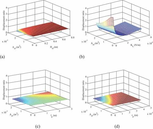
The results depicted in show that the maximum acceleration and displacement response is greatly affected by the air balloon effective area (Aef) and height (Hef) and the U-shaped landing gear stiffness (KL). A two-dimensional plot of a particular pair of these independent variables is used to obtain quantitative information about the effect of the variables on the acceleration and displacement ratio.
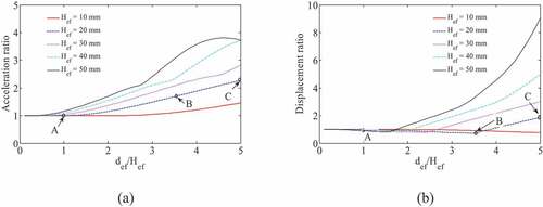
shows the influence of the air spring balloon diameter on the acceleration and displacement ratio for KL = 1.2 × 10⁴ N/m. The air spring balloon diameter (def) is normalized to the air damper height (Hef). As shown in ), the acceleration ratio increases when the diameter of an air balloon is increased. This condition is due to the increase in the air spring stiffness. The displacement ratio is almost constant for def/Hef smaller than 1.5 as shown in ). For def/Hef larger than 1.5, the displacement ratio increases when the diameter of the air balloon is increased.
Figure 9. def/Hef vs acceleration and displacement ratio for KL = 1.2 × 10⁴ N/m
shows the acceleration and displacement response of the UAV mass for KL = 1.2 × 10⁴ N/m, Hef = 20 mm and def/Hef = 1, 3.7 and 5 (point A, B, and C in ). As depicted in , the contact period at point A is larger than those at points B and C. These results indicate that the landing gear stiffness at point A is smaller in comparison to those at points B and C. The maximum displacement at point A occurs during contact condition; however, the maximum displacement at point B and C occurs during rebound condition.
Figure 10. UAV mass response for KL = 1.2 × 10⁴ N/m and Hef = 20 mm
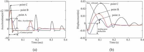
Based on the results obtained from , it can be concluded that a large stiffness landing gear will increase the maximum acceleration response and reduce the spring deflection. However, it also increases the maximum rebound displacement that can reduce the UAV steering stability after landing.
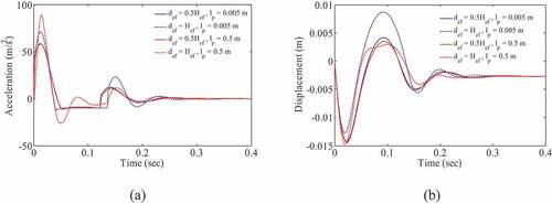
shows the UAV mass acceleration and displacement responses obtained using two values of balloon diameter (def) and the connecting pipe length (lp). As depicted in , the variation of the air balloon diameter and the connecting pipe length not only affects the maximum response amplitude but also the settling time. The displacement response in ) shows that increasing the balloon diameter or the balloon effective area will increase the settling time. On the contrary, increasing the connecting pipe length will reduce the settling time.
Figure 11. Acceleration and displacement responses with variation def and lp.
3.1.2. Harmonic vibration response of UAV system
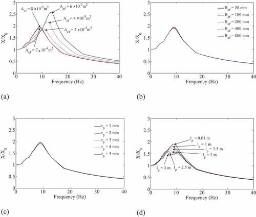
Evaluation of UAV harmonic response is performed by applying the base excitation on the UAV wheel. The excitation displacement amplitude is X0 = 0.001 m, and the excitation frequency varies from 0 Hz to 40 Hz. The calculated system natural frequency is fn1 = 10 Hz, fn2 = 100 Hz, and fn3 = 200 Hz. shows the ratio between the UAV displacement response amplitude and the base excitation amplitude (X/X0) in the frequency domain. The effect of cross-sectional area (Aef) variation on the displacement amplitude ratio is depicted in ). The displacement amplitude ratio becomes smaller when Aef increases from 8 × 10⁻⁵ m2 until 2 × 10⁻³ m2. However, further increase in Aef causes increase in the displacement amplitude ratio. This phenomenon occurs due to the rebound motion of the landing gear when Aef is larger than 2 × 10⁻³ m2. The influence of Hef on the displacement amplitude ratio is shown in ). It is shown from ) that there is no significant effect of Hef variation on the displacement amplitude ratio. ) shows the relationship between rp variation and the displacement amplitude ratio. At the resonance frequency, the displacement amplitude ratio increases when rp is increased from 1 mm to 2 mm. However, further increasing of rp has no significant effect on the value of the displacement amplitude ratio. The effect of pipe length variation (lp) on the displacement amplitude ratio is shown in ). The displacement amplitude ratio decreases when lp increases. The reason for this condition is that the air oscillation inside the connecting pipe becomes dominant when the pipe length is large. Therefore, a significant resonance peak occurs due to the air vibration.
Figure 12. Frequency response function (Xp/X0) vs air damper parameters variation
3.2. Experimental study
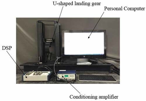
The experimental set-up of the landing gear system is depicted in . The landing gear system is released from a predefined initial elevation and moves freely on the rail track that is fixed on two vertical beams, as shown in . A piezotronics accelerometer sensor is positioned on top of mass M to detect the acceleration of M in the instant after the wheel contacts with the ground. The acceleration signal from the accelerometer is conditioned using a four-channel conditioning amplifier and acquired by the National Instrument digital signal processing system (DSP). The acquired signal is post-processed on a PC using MATLAB software.
Figure 13. Experimental setup
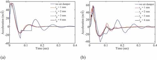
shows a comparison of the acceleration response obtained from simulation and the experiment. As depicted in , the experimental data can verify the simulation results. The maximum acceleration peak obtained with the air damper is slightly higher than that obtained without the air damper. However, the steady-state response decreases when using the air damper system. In the case of the landing gear system with the air damper, the system’s natural frequency from the experimental data is higher than that from the simulation result. This result may be due to the nonlinear wheel contact condition that is modeled by the linear spring and dashpot elements in the simulation study.
Figure 14. Time response of UAV body. (a) Simulation and (b) experiment
4. Conclusions
A new method for increasing the damping of the U-shaped landing gear system using the air damper has been proposed. Several conclusions are obtained from the simulation study.
The linear response calculation using modal analysis indicates that the response of the landing gear system is significantly affected by the first mode of vibration.
For shock vibration problem during landing, increasing the effective area and reducing the effective height of the air balloon causes an increase in the maximum acceleration response and in the settling time of the displacement response. Conversely, increasing the connecting pipe length will reduce the maximum acceleration response and the settling time of the displacement response.
A low stiffness air spring system using an air balloon with a large effective area and short effective height can reduce the acceleration amplitude and rebound displacement. However, it also increases the landing gear deflection.
The displacement ratio (X/X0) under harmonic excitation is greatly affected by the air balloon cross-sectional area (Aef) and the connecting pipe length (lp) . The displacement ratio increases with increasing of Aef and decreases with increasing of lp increasing.
Acknowledgements
Publication of this article is supported by the Engineering Faculty of Andalas University grant under contract No.: 020/UN.16.09.D/PL/2020. The authors also appreciate financial funding from Universitas Sebelas Maret for Hibah PNBP (non APBN 2021).
Additional information
Funding
Notes on contributors
Ubaidillah Ubaidillah
All persons who meet authorship criteria are listed as authors, and all authors certify that they have participated sufficiently in the work to take public responsibility for the content, including participation in the concept, design, analysis, writing, or revision of the manuscript. Furthermore, each author certifies that this material or similar material has not been and will not be submitted to or published in any other publication before its appearance in the Cogent Engineering Journal. All authors have contributed to the whole research work. Conception and design of study: L. Son, M. Surya, M. Bur; Acquisition of data: L. Son, M. Surya; Analysis and/or interpretation of data: L. Son, M. Bur. Drafting the manuscript: L. Son, M. Surya; Revising the manuscript critically for important intellectual content: L. Son, M. Bur, Ubaidillah. Approval of the version of the manuscript to be published: L. Son, M. Bur, Ubaidillah, R. Dhelika.
References
- Ahmad, M. A., Shah, S. I. A., & Shams, T. A. (2020). Comprehensive design of an oleo-pneumatic nose landing gear strut. J. Of Aerospace. Eng. First published December 13, 2020. https://doi.org/10.1177/0954410020979378
- Asthana, C. B., & Bhat, R. B. (2012). A novel design of landing gear oleo strut damper using MR fluid for aircraft and UAV’s. App. Mech. And Mat, 225, 275–16. doi: 10.4028/www.scientific.net/amm.225.275.
- Carames, T. M. F., Novoa, O. B., Miguez, I. F., & Lamas, P. F. (2019). Towards an autonomous industry 4.0 warehouse: A UAV and blockchain-based system for inventory and traceability applications in big data-driven supply chain management. Sensors, 19(2394). doi: 10.3390/s19102394.
- Dragus, L., Ciobanu, I., Mazăre, C., Alexei, A., Barbareso, M., & Stanciu, F. (2019). Design a composite materials landing gear. J. Physics: Conf. Series, 1297 012008. https://iopscience.iop.org/article/ 10.1088/1742-6596/1297/1/012008.
- Eisenbeiss, H., & Zhang, L. (2006). Comparison of DSMs generated from mini UAV imagery and terrestrial laser scanner in a cultural heritage application. Proceedings of the International Archives of Photogrammetry, Remote Sensing and Spatial Information Sciences, Dresden. https://doi.org/10.3929/ethz-b-000158047
- Faraj, R., Graczykowski, C., & Szulc, J. H. (2018). Adaptable pneumatic shock absorber. J. Of Vib. And Cont, 24(3), 711-721. First published August 27, 2018. doi: 10.1177/1077546318795532.
- Fuqaha, A. A., Guizani, M., Khreishah, A., Othman, N. S., Khalil, I., Almaita, E., Dou, Z., Sawalmeh, A., Fuqaha, A. A., Guizani, M., Khreishah, A., Othman, N. S., Khalil, I., Almaita, E., & Dou, Z. (2018). Unmanned aerial vehicles: A survey on civil applications and key research challenges. arXiv:1805.00881. (11). doi: 10.1109/ACCESS.2019.2909530.
- Gualdi, S., Morandini, M., & Ghiringhelli, G. L. (2008). Anti-skid induced aircraft landing gear instability. Aerospace Science and Technology, 12(8), 627–637. doi: 10.1016/j.ast.2008.02.002.
- Ubaidillah, Lenggana, B. W., Son, L., Imaduddin, F., Widodo, P. J., & Doewes, R. I. (2020). A new magnetorheological fluids damper for unmanned aerial vehicles. J. Of Adv. Res. In Fluid Mech. And Therm. Sci, 73 (1), 35–45. doi: 10.37934/arfmts.73.1.3545.
- Lopes, E. D. R., & Ayala, H. V. H. (2020). Nonlinear grey-box identification of a landing gear based on drop test data. Anais Da Sociedade Brasileira De Automática, 2(1). https://doi.org/10.48011/asba.v2i1.1299
- Luo, C., Zhao, W., Du, Z., & Yu, L. (2019). A neural network based landing method for an unmanned aerial vehicle with soft landing gears. Appl. Sci, 9(15), 2976. doi: 10.3390/app9152976.
- Mikulowski, G., Pawlowski, P., Graczykowski, C., Wiszoway, R., & Holnocki-Szulc, J. (2009). On a pneumatic adaptive landing gear system for a small aerial vehicle. Proceedings of the IV Eccomas Thematic Conference on Smart Structure and Materials, 13-15 July, Porto.
- Moheyeldein, M. M., Abd-El Tawwab, A. M., Abd El-gwwad, K. A., & Salem, M. M. M. (2018). An analytical study of the performance indices of air suspensions over the passive suspension. Beni-Suef Univ. J. Of Basic and App. Sci, 7(4), 525–534. doi: 10.1016/j.bjbas.2018.06.004.
- Orlando, C. (2020). Nose landing gear simple adaptive shimmy suppression system. Journal of Guidance, Control, and Dynamics, 43(7), 1–15. https://doi.org/10.2514/1.G004832
- Puri, A., Valavanis, K. P., & Kontitsis, M. (2007). Statistical profile generation for traffic monitoring using real-time UAV based video data. Proceedings of 15th Mediterranean Conference on Control & Automation, Athens. https://doi.org/10.1109/MED.2007.4433658
- Rahmani, M., & Behdinan, K. (2020). Structural design and optimization of a novel shimmy damper for nose landing gears. Structural and Multidisciplinary Optimization, 62(5), 2783–2803. doi: 10.1007/s00158-020-02628-x.
- Son, L., Bur, M., & Rusli, M. (2018). A new concept for UAV landing gear shock vibration control using pre-straining spring momentum exchange impact damper. Journal of Vibration and Control, 24(8), 1455–1468. doi: 10.1177/1077546316661470.
- Son, L., & Huda, S. (2019). Impact vibration response attenuation using four-bar linkage landing gear system. Journal of Physics: Conference Series, 1349. doi: 10.1088/1742-6596/1349/1/012060.
- Sugiura, R., & Ishii, K. (2005). Remote-sensing technology for vegetation monitoring using an unmanned helicopter. Journal of Biosystems Engineering, 90(4), 369–379. doi: 10.1016/j.biosystemseng.2004.12.011.
- Tkáč, M., & Mésároš, P. (2019). Utilizing drone technology in the civil engineering. Journal of Civil Engineering, 14(1), 27–37. doi: 10.1515/sspjce-2019-0003.
- Wang, H., Xing, J. T., Price, W. G., & Weiji, L. (2008). An investigation of an active landing gear system to reduce aircraft vibrations caused by landing impacts and runway excitations. Journal of Sound and Vibration, 317(1–2), 50–66. doi: 10.1016/j.jsv.2008.03.016.
- Zhu, S., Wang, P., & Tian, J. (2011). Experimental research on aircraft landing gear drop test based on MRF damper. Procedia Engineering, 15, 4712–4717. doi: 10.1016/j.proeng.2011.08.882.