
Abstract
Due to intrinsic or extrinsic conditions, the number of car accidents has increased currently across the globe. Drivers must be assured that they can avoid these problematic conditions. According to the statistics, about 10,000 are dead, and more than a million people are wounded each year in India. Hence, improvement in the safety of vehicles is of utmost importance to shoot down the number of accidents. The automotive bumper beam is one of the essential components in passenger cars. Bumper beams reduce or minimize the extent of impact caused at the front and rear ends during a collision in passenger vehicles. It absorbs the impact energy. The important physical parameters in the bumper beams such as material, size, and design to improve the extent of crashworthiness are studied and discussed in this current work. Comparative analysis between 2 mm thickness and 4 mm thickness bumper with honeycomb structure is studied. An ideal design composition is considered. This helps in advanced safety precautions.
PUBLIC INTEREST STATEMENT
Due to intrinsic or extrinsic conditions, the number of car accidents has increased currently across the globe. In automobiles, a bumper is a component that is placed at the front and rear end of the car. It is designed to withstand and reduce the amount of impact considering the vehicle’s safety systems. In this work finite element analysis is carried out to investigate the existing bumper by replacing new honeycomb structures with different sizes. This work will help the automotive industries to know the effect of honeycomb structures on the bumper. Honeycomb structures can be replaced with the presently existing designs as it is having more energy absorbing capacity. Concerning the point of safety, the occupant will be safeguarded during the impact or collision.
1. Introduction
In automobiles, a bumper is a component that is placed at the front and rear end of the car. It is designed to withstand and reduce the amount of impact considering the vehicle’s safety systems. However, during high-speed collisions, they fail to reduce the injury caused to the vehicle, but advanced-level bumpers are being designed to mitigate injury to pedestrians hit by cars. The main usage of car bumper is to reduce the impact during a collision. These are installed on the front and rear end of the vehicle which is a highly exposed area during low-speed accidents. It enhances the handling and performance level of the vehicle. The automotive bumper system protects the hood, grill, fuel and exhaust systems, cooling system, and helps in towing capabilities of the vehicle.
Fascia: Bumper fascia must be aerodynamic, lightweight, and from the customer’s point of view, it must be suitable to the car model and acceptable according to the customer’s choice. It is the front most of the bumper []. Usually, fascia is made of polypropylene, polyurethane, or polycarbonate (Lee et al., Citation2009).
Figure 1. Configuration of common bumper (Lee et al., Citation2009)
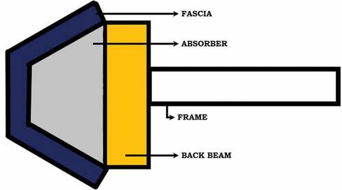
Energy absorbers: Energy absorbers absorb a portion of the kinetic energy from a vehicle collision. Types include foam, honeycomb, and mechanical ones (Lee et al., Citation2009). Most types of materials are used in the manufacturing of a car bumper. Materials with different physical and chemical properties are used for bumpers. To be listed, Chrome plated steel is on among. It has simple properties, easily dents, but is heavy and expensive. As the world shifted towards more usage of plastics, which is lightweight and cost effective at the same time, reinforced thermoplastic olefins are employed in the manufacturing of car bumpers. Thermoplastic’s properties are suitable for the application of car bumpers, as they can be easily molded, resistant to high-impact, and provide required cushioning to dissipate energy. Ansys R-19 is used in the current study. Ansys is used in analyzing medical implants to evaluate the performance of medical implants and different human organs like bones, teeth, tissue, etc. (Chethan, Zuber et al., Citation2019)(Chethan, Bhat et al., Citation2019)(Chethan, Shyamasunder Bhat et al., Citation2019). Also using Ansys the concrete structures are evaluated (Celarec & Dolšek, Citation2013) (Castaldo et al., Citation2019)(Castaldo et al., Citation2020). In this current work, the vehicles that are considered are in the class of passenger sedan vehicles and we studied honeycomb structure as a shock-absorbing structure. In addition, to shock-absorbing characteristics, it also provides an exceptional strength-to-weight ratio and has high unidirectional compression resistance. Furthermore, we also incorporated changes in size, design, and material of the honeycomb structure to determine the most effective combination of these parameters.
1.1. Impact mechanics
In the computational studies, the barrier is set to be rigid and the bumper model is set to be hitting the target at 64 kmph (Van Ratingen et al., Citation2016) and the required information is collected utilizing ANSYS 19.0.
It is critical in investigating the effects to recognize the diverse outcomes of effects that occur, impacts like plastic and elastic are both to be evaluated. In a versatile effect, an immaterial measure of vitality is lost between the two affecting bodies, for example, the collision between two billiard balls. A plastic impact includes a lot of vitality dispersed in the crash. An effect between any two vehicles or between one vehicle and a rigid body, where the vehicles affected due to high impact, is a case of an elastoplastic impact (Wang & Li, Citation2015). According to the law of nature, during and after the collision, the total energy of the system is conserved. The system’s internal energy is zero and kinetic energy is maximum at the initial condition (time = 0 s). The energy of the system (bumper) is equal to the initial kinetic energy of the vehicle. Transformation of kinetic energy into internal energy during collision takes place and plastic deformation can be noticed in the automotive body parts. This signs a decrease in the kinetic energy and a gradual increase in internal energy. Once the energy conservation takes place at a particular speed, minimal to no change is observed in the kinetic and internal energy after the impact (Wang & Li, Citation2015)(Özütok & Madenci, Citation2017).
Honeycomb is a simple structure that is composed of hexagonal-shaped foil cells as shown in . The name is derived from its close resemblance to a bee honeycomb structure, no variation in the depth direction can be noticed. These hexagonal cell structure has considerable rigid properties like high shear and crushing stress, almost constant crushing force, long-stroke, low weight, and relative insensitivity to local loss of stability. Due to the exceptional mechanical properties combined along with a high strength-to-weight ratio, sandwich panels are of high importance and are highly used in aerospace, automobile, and marine industries (PTRS, Citation2006)(Madenci & Özütok, Citation2017). These sandwich panels used in automobiles play a major role in the safety and protection of passengers. The sandwich panels are mainly applied on the pillars, body shell, and along the roofline as high-grade energy absorption units during impacts (Ko et al., Citation2009). Due to its wide use and sophisticated composition in the respective fields, research on the impact behavior and energy-absorption characteristics of honeycomb sandwich panel (HSP) has been increasing and its applications are also being studied.
Figure 2. NCAP level for low-speed frontal impact (Hs, Citation2007)
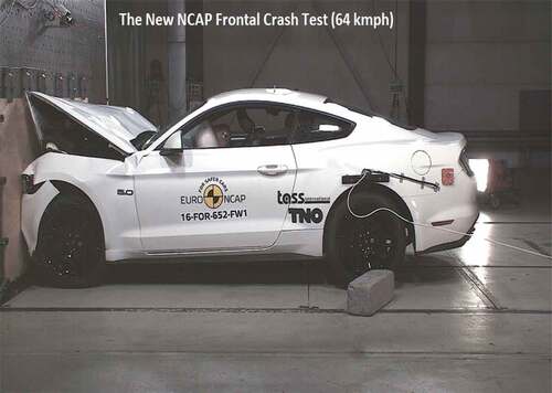
Figure 3. The nomenclature of the honeycomb (Thomas & Tiwari, Citation2019)
1.2. Aluminum honeycomb
Over the decades, the statistics in structural and characteristic applications of the honeycomb structures in various industries have risen, the main reason being some of its technical properties like greater strength to weight ratio, economical advantages, low cost, and better energy absorption capabilities. Materials such as Aluminium Nomex, ceramic, and polymers are usually used in the manufacturing of honeycomb structures. Among the materials mentioned, Aluminium honeycombs are being used in various industries and as a core material in various engineering fields such as aerospace, automotive, aviation, and many other mechanical-related fields (Chethan, Keni et al., Citation2018)(Chethan, Pai et al., Citation2018). A wide range of studies and corresponding experiments have been conducted on the aluminum honeycomb specimens regarding compression tests at given different intermediate strain rates (Zhou & Mayer, Citation2016) (Mozafari et al., Citation2015)(Baker et al., Citation1998). FEM studies are also performed considering aluminum alloys (Castaldo, Nastri, Piluso et al., Citation2017a)(Castaldo, Nastri, Piluso et al., Citation2017b). The above mentioned carried on such compression-related tests on the honeycomb structures in out-of-plane direction at different strain rates. This resulted in a linear relation between plateau stress and strain rate i.e., plateau stress increased eventually with strain rate ε. Both (Xu et al., Citation2012) and (Ashab et al., Citation2015) found that with the increase in t/l ratio, i.e. in simpler words, cell wall thickness to edge length ratio and strain rate, plateau stress, increased. According to (Sharma K V & YRT, Citation2014) experiment, the energy absorption capacity of the aluminum honeycomb increased with an increase in the impact velocity in out-of-plane compression load. Various experiments were conducted on foam-filled aluminum hexagonal honeycombs under the out-of-plane compression loads (Alavinia & Sadeghi, Citation2013). According to their observation, with an increase in the strain rate, the crushing strength of foam-filled and bare honeycombs increased. According to the findings, more sensitive strain-rate output was noted in bare honeycombs compared to foam-filled honeycombs. (Mozafari et al., Citation2015) employed ABAQUS software and as per the results, the mean crushing strength and energy absorption of foam-filled honeycomb tends to be greater as compared to the sum of those of bare honeycomb and foam. Along with the above-mentioned experimental study, various researchers also employed the Finite Element Analysis (FEA) technique to study the mechanical behavior of aluminum honeycombs under varied given conditions. (Guo & LJG, Citation1999) conducted a numerical analysis of the impact and amount of damage in the honeycomb properties in the in-plane direction. According to the analysis and report, a decreasing pattern in the modulus and strength due to the effect of single, isolated defects of various sizes was noticed. Along with the recently mentioned, investigation on the separation distance between two defects and its respective effect on the Young’s Modulus and its plastic collapse strength was also studied (Hu et al., Citation2014)(Hu et al., Citation2013). The finite Element Analysis method was undertaken to study the in-plane crushing of aluminum honeycombs. Dynamic sensitivity index was proposed to explain the crushing strength and energy absorption of the system. To study and analyze the out-of-plane dynamic properties of aluminum hexagonal honeycomb cores during compression (Deqiang et al., Citation2010) used ANSYS/LS-DYNA. As a result and according to the power laws, it was noticed that there was a relationship between the out-of-plane dynamic plateau stresses of honeycombs to the expanding angle θ, impact velocity, cell wall thickness-to-edge length ratio of honeycombs.
The number of experiments, to study the indentation process, were conducted on aluminum honeycombs (Zhou & Mayer, Citation2016)(Ashab et al., Citation2015) were limited and took place at very low and intermediate strain rates. Quasi-static indentation tests on aluminum honeycombs were conducted by (Zhou & Mayer, Citation2016) to study the behavior of the size of the specimen on the force versus displacement curve.
1.3. Polymer honeycomb
The discovery of honeycomb polymeric sandwich structure has proven to be an excellent innovation and boon in the composites industry due to its various advantages such as lightweight, smooth skin finish, and possessing excellent fatigue resistance. The typical composition consists of two thin face sheet materials which are attached to an array of open cells, with typical hexagons or other cell configurations. This structure is commonly used in applications ranging from sandwich panels for aircraft, automobiles, and the construction industry to energy absorption, directing airflow, acoustic panels, and light diffusion. Some of the common polymeric honeycomb structures that are commercially available are made of polypropylene, polyurethane, and polycarbonate (Fischer et al., Citation2009).
2. Methodology
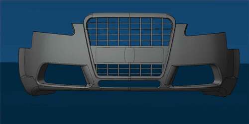
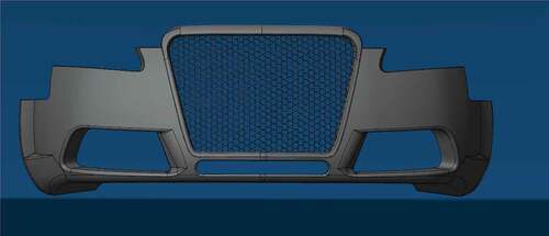
A honeycomb structure is modeled and the same is considered for the analysis. It acts as a shock-absorbing structure. For comparative study, an existing bumper design of a passenger vehicle is taken into consideration (Wang & Li, Citation2015)(Mekalke, Citation2014)(Kiran NS & BA, Citation2014)(Raj Kumar et al., Citation2019)(Kannan et al., Citation2020). Considering the basic design modifications are then made in the original design such that the front bumper grills are replaced with different honeycomb model designs. Crash analysis is carried out according to NCAP regulations and safety standards (Van Ratingen et al., Citation2016)(Afripin et al., Citation2019). Finite element analysis is carried out using Ansys 18.0 (Chethan & Ogulcan et al., Citation2020)(Chethan, Zuber et al., Citation2019). According to NCAP regulations, the bumper is made to crash into a rigid barrier [] (in this case, a rigid wall). Most countries follow the FMVSS 208 (Occupant crash protection) testing standards which focus on the safety of the automobile parts as well as on the safety of the pedestrian (Kumbhar et al., Citation2017)(Mao et al., Citation2006). Accordingly, different shock-absorbing structures are used in modern-day frontal car bumpers to meet these requirements (Muhammad et al., Citation2017)(Sonawane & Shelar, Citation2018). A comparative study is carried out for different combinations of honeycomb structure designs to determine the stresses developed in each case and to optimize the design, size, and material of honeycomb structure in a frontal car bumper. Initially, the bumper design of the passenger vehicle was selected, and using its blueprint a three-dimensional model is designed. shows the original model of the passenger vehicle’s frontal bumper.
Figure 4. The original model of passenger vehicle frontal bumper
2.1. Modeling of honeycomb structures
The conventional bumper is replaced by the modified hexagonal honeycomb structure. These structures were modeled with a thickness of 2 mm and 4 mm. The diameter and extruded length of the structure kept constant of 35 mm and 15 mm respectively (CitationGrall & Zeitouni). shows the replacement of the frontal grills in the original design. [New proposed perforated conceptual design of the car bumper.]
Figure 5. Design of perforated conceptual design of the car bumper
2.2. Meshing and boundary conditions
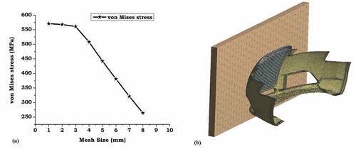
In the current work, the unstructured mesh was used. A wall is designed to carry out the crash testing and this wall will act as a barrier into which the bumper model is made to crash. Thereafter meshing of the individual systems is done. To finalize the mesh size for the analysis mesh grid independence study is carried out. shows the mesh grid independence results. Mesh sizes were varied from 8 mm to 1 mm with an interval of 1 mm. It is observed that there was variation in von Mises stresses when the mesh sizes were varied from higher mesh sizes to lower mesh sizes. It is also observed that beyond 2 mm size the variation was found to be less than 5%. So mesh size of 2 mm is finalized for all the analysis carried out. shows the meshed bumper with a rigid wall. Solid 185 element is considered for the analysis. The total number of elements was 295,823 and nodes 143,400. Models are used in explicit dynamics analysis. The contact is considered as body interactions with frictionless contact.
Figure 6. (a) Mesh independency graph. Variation of the stress values with a change in mesh size is illustrated. (b) Meshed bumper with a rigid wall
After the finalization of meshing, the boundary conditions are applied. Wall is considered as a rigid body and fixed in all directions. The bumper model is given a velocity of 64 Kmph in the direction of the rigid wall (Van Ratingen et al., Citation2016). The velocity is kept constant for all the models. Aluminum is considered for bumper models. The wall is made to be of concrete material and acts as fixed support. The mechanical properties of the materials are given in below:
Table 1. Mechanical properties of aluminium alloy 5052 (Bhowmik & Srivas AK, Citation2016)(Bhowmik & Mishra, Citation2018)
3. Results
Modeled bumpers are analyzed at an impact speed of 64 Kmph (17.77 m/s) according to the NCAP tests of the automotive vehicles (Pewekar & Sandye, Citation2018)(Rajaraman et al., Citation2017). Models are intended to make an impact on a rigid body to get all the details that are needed to analyze the bumpers. These bumpers are analyzed on the grounds of Equivalent stress.
3.1. Honeycomb cell size with perforated-type honeycomb design (2 mm thickness)
The equivalent von mises stresses were considered on the frontal fascia, outer case. Only on honeycomb structure and on the entire bumper. shows the results on each case and also the shows von Mises stresses on these components.
Figure 7. (a) Equivalent Stress on the frontal fascia, (b) equivalent Stress on the outer case, (c) equivalent Stress on the honeycomb structure and (d) equivalent stress on the entire bumper (2 mm thickness)
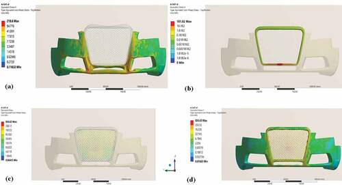
Table 2. Equivalent stress values in different bumper parts
3.2. Honeycomb cell size with perforated-type honeycomb design (4 mm thickness)
The equivalent von mises stresses were considered on the frontal fascia, outer case. Only on honeycomb structure and on the entire bumper. shows the results on each case and also the shows von Mises stresses on these components.
Figure 8. (a) Equivalent Stress on the frontal fascia, (b) equivalent Stress on the outer case, (c) equivalent Stress on the honeycomb structure and (d) equivalent stress on the entire bumper (4 mm thickness)
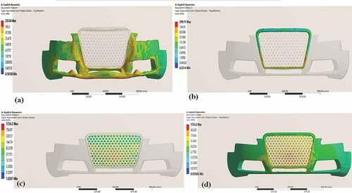
Table 3. Equivalent stress values in different bumper parts
4. Discussion
In the current work, the generalized design of the car bumper is replaced by the honeycomb structure. The honeycomb structure is modeled in two ways with varying thicknesses. Both models are subject to impact against the concrete wall. Modeled bumpers are analyzed at an impact speed of 64 Kmph (17.77 m/s) according to the NCAP tests of the automotive vehicles (Pewekar & Sandye, Citation2018)(Rajaraman et al., Citation2017). It was observed the there was an increase in the equivalent von Mises stress when the thickness is increased from 2 mm to 4 mm. The simulation results of the bumper with aluminum alloy 5052 shows that the honeycomb structure will absorb more loads compare to the frontal fascia and outer case. This is due to the compressive strength with respect to dynamics strain and energy absorption capability of the honeycomb structure. the comparative analysis between 2 mm thickness and 4 mm thickness bumper with honeycomb structure. It was observed that the honeycomb takes all the stresses induced in the bumper.
Figure 9. Comparative analysis between 2 mm thickness and 4 mm thickness bumper
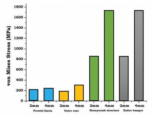
There was no significant change in the von Mises stresses observed in the frontal fascia and the outer case of the bumper. The stresses were more than two times in the honeycomb structure. This indicates that with the increases in the thickness of the structure it tends to absorb more impact energy and finally helps to avoid adverse effects to passengers due to the collision. In this current work, only equivalent stresses are evaluated to know the impact energy absorption capacity in the conceptional design of the bumper developed. There will be deformation associated whenever the impact takes place with greater speed. Deformation is not reported and neglected because whenever collision takes place the complete bumper will be replaced and also the main objective of the work is to know the effect of the absorption capacity in the newly conceptional design and with change in the thickness of the structure.
4.1. Limitations
In this work, a complete analysis was performed considering the impact speed of 64 Kmph (17.77 m/s). However different speeds can be considered to know the effect of impact speed on the honeycomb structure. Also in the current analysis aluminum is considered as bumper material. Nowadays aluminum is tried to replace by carbon-carbon fiber matrix. So composite materials with heterogeneous properties can be considered for the analysis. This model can be fabricated with the optimized material and an experimental impact test can be performed.
5. Conclusion
In the current work, a conceptional new design of the honeycomb structure is modeled. These models are varied in thickness. Impact analysis is carried out to know the effect of thickness of the structure. It was observed that with an increase in the thickness of the honeycomb structures related to absorption of more impact energy also honeycomb structure takes all the impact caused during the collision. The simulation results of the bumper with aluminum alloy 5052 shows that the honeycomb structure will absorb more loads compare to the frontal fascia and outer case. This is due to the compressive strength with respect to dynamics strain and energy absorption capability of the honeycomb structure. However, this work can be further analyzed by using the combination of the different materials and also impacts at different rigid bodies. Further speeds during the impact can also be analyzed to get a clear idea about how exactly the new design behaves during different scenarios.
Acknowledgements
The authors thank the Department of Aeronautical and Automobile Engineering, Manipal Institute of Technology, Manipal Academy of Higher Education, Manipal, Karnataka, INDIA for providing thecomputational facility to carry out this research.
Disclosure statement
No potential conflict of interest was reported by the author(s).
Additional information
Funding
Notes on contributors

Chethan K N
Dr. Chethan K N working as Assistant Professor-Senior Scale in the Department of Aeronautical and Automobile Engineering, Manipal Institute of Technology, Manipal Academy of Higher Education, Manipal, Karnataka, INDIA. He holds B.E. (Mechanical Engineering), M.Tech (Manufacturing Engineering & Technology) and Ph.D. (Computational Biomechanics) degrees. He has a more than Nine years of teaching and research experience. His area of interest includes Biomechanics of the hip joint, Finite element analysis of biomedical implants, Composite materials, and Manufacturing of medical implants. The author has published several articles in reputed journals related to finite element analysis of hip implants, mechanical characterization of materials, and composite materials.
References
- Afripin, M. A. A., Zainudin, A. Z., Sahar, M. A. H. F. M., & Yusof, M. (2019). Frontal impact on bus superstructure as per UNECE R29 and NCAP. IOP Conf Ser Mater Sci Eng, 670, 012014. https://doi.org/10.1088/1757-899X/670/1/012014
- Alavinia, A., & Sadeghi, M. Z. (2013). An experimental investigation on the effect of strain rate on the behaviour of bare and foam-filled aluminium honeycombs. J Mater, 52, 748–756. https://doi.org/10.1016/j.matdes.2013.06.006
- ASM Ashab, A. S. M., Ruan, D., Lu, G., et al (2015). Experimental investigation of the mechanical behavior of aluminum honeycombs under quasi-static and dynamic indentation. J Mater, 74, 138–11. https://doi.org/10.1016/j.matdes.2015.03.004
- Baker, W. E., Togami, T. C., & Weydert, J. C. (1998). HIGH-DENSITY METAL HONEYCOMBS (Vol. 21, pp. 149–163).
- Bhowmik, A., & Mishra, D. (2018). A Comprehensive Study of an Aluminum Alloy AL-5052. Adv Phys Lett, 3(1), 20–22. http://www.irdindia.in/journal_apl/pdf/vol3_iss1/5.pdf http://www.irdindia.in/journal_apl/pdf/vol3_iss1/5.pdf
- Bhowmik, A., & Srivas AK, S. P. (2016). A Review of the properties of Aluminum Alloy Al 5052. J Sci Res Allied Sci, 2, 25–30. http://jusres.com/home/archive_show/2016/5/2
- Castaldo, P., Gino, D., Bertagnoli, G., & Mancini, G. (2020). Resistance model uncertainty in non-linear finite element analyses of cyclically loaded reinforced concrete systems. Engineering Structures, 211, 110496. https://doi.org/10.1016/j.engstruct.2020.110496
- Castaldo, P., Gino, D., & Mancini, G. (2019). Safety formats for non-linear finite element analysis of reinforced concrete structures: Discussion, comparison and proposals. Eng Struct, 193, 136–153. https://doi.org/10.1016/j.engstruct.2019.05.029
- Castaldo, P., Nastri, E., & Piluso, V. (2017a). FEM simulations and rotation capacity evaluation for RHS temper T4 aluminium alloy beams. Compos Part B Eng, 115, 124–137. https://doi.org/10.1016/j.compositesb.2016.10.026
- Castaldo, P., Nastri, E., & Piluso, V. (2017b). Ultimate behaviour of RHS temper T6 aluminium alloy beams subjected to non-uniform bending: Parametric analysis. Thin-Walled Struct, 115, 129–141. https://doi.org/10.1016/j.tws.2017.02.006
- Celarec, D., & Dolšek, M. (2013). The impact of modelling uncertainties on the seismic performance assessment of reinforced concrete frame buildings. Eng Struct, 52, 340–354. https://doi.org/10.1016/j.engstruct.2013.02.036
- Chethan, K. N., Bhat, S. N., Zuber, M., & Shenoy, S. B. (2019). Patient-Specific Static Structural Analysis of Femur Bone of different lengths. Open Biomed Eng J, 12, 108–114. https://doi.org/10.2174/1874120701812010108
- Chethan, K. N., Keni, L. G., Padmaraj, N. H., et al (2018). Fabrication and Mechanical characterization of aluminium [6061] with conventionally prepared bamboo charcoal. Mater Today Proc, 5(2), 3465–3475. https://doi.org/10.1016/j.matpr.2017.11.593
- Chethan, K. N., Ogulcan, G., . N. S. B., et al (2020). Wear estimation of trapezoidal and circular shaped hip implants along with varying taper trunnion radiuses using finite element method. Comput Methods Programs Biomed. 196, 1–9. https://doi.org/10.1016/j.cmpb.2020.105597.
- Chethan, K. N., Pai, A., Padmaraj, N. H., et al (2018). Effect of bamboo char and boron carbide particles on mechanical characteristics of Aluminum 6061 hybrid composites. IOP Conf Ser Mater Sci Eng, 377, 012038. https://doi.org/10.1088/1757-899X/377/1/012038
- Chethan, K. N., Shyamasunder Bhat, N., Zuber, M., & Satish Shenoy, B. (2019). Finite element analysis of different hip implant designs along with femur under static loading conditions. J Biomed Phys Eng, 9, 507–516. https://doi.org/10.31661/jbpe.v0i0.1210
- Chethan, K. N., Zuber, M., Bhat, N. S., et al (2019). Static structural analysis of different stem designs used in total hip arthroplasty using finite element method. Heliyon, 5(6), e01767. https://doi.org/10.1016/j.heliyon.2019.e01767
- Chethan, K. N., Zuber, M., Bhat, S. N., & Shenoy, S. B. (2019). Comparative Study of Femur Bone Having Different Boundary Conditions and Bone Structure Using Finite Element Method. Open Biomed Eng J, 12(1), 115–134. https://doi.org/10.2174/1874120701812010115
- Deqiang, S., Weihong, Z., & Yanbin, W. (2010). Mean out-of-plane dynamic plateau stresses of hexagonal honeycomb cores under impact loadings. Compos Struct, 92(11), 2609–2621. https://doi.org/10.1016/j.compstruct.2010.03.016
- Fischer, S., Drechsler, K., Kilchert, S., & Johnson, A. (2009). Composites : Part A Mechanical tests for foldcore base material properties. Compos Part A, 40(12), 1941–1952. https://doi.org/10.1016/j.compositesa.2009.03.005
- Grall, L., & Zeitouni, R. Adalian C No Title (pp. 1–13).
- Guo, X. E., & LJG, R. (1999). Behavior of intact and damaged honeycombs: A finite element study. International Journal of Mechanical Sciences, 41(1), 85–105. https://doi.org/10.1016/S0020-7403(98)00037-X
- Hs, D. O. T. (2007). The New Car Assessment Program Suggested Approaches for Future Program Enhancements. Federal Register.
- Hu, L., You, F., & Yu, T. (2013). Effect of cell-wall angle on the in-plane crushing behaviour of hexagonal honeycombs. Mater Des, 46, 511–523. https://doi.org/10.1016/j.matdes.2012.10.050
- Hu, L., You, F., & Yu, T. (2014). Analyses on the dynamic strength of honeycombs under the y -directional crushing. J Mater, 53, 293–301. https://doi.org/10.1016/j.matdes.2013.06.076
- Kannan, V. S., Surendar, J. S., Sundaram, S. C. M., et al (2020). Crash Analysis on Automobile Bumpers. IOP Conf Ser Mater Sci Eng 923:, 923, 012018. https://doi.org/10.1088/1757-899X/923/1/012018
- Kiran NS, V. S. N. C. D., & BA, R. (2014). Fea Analysis (Dynamic) on a Passenger Car Bumper Body Material (Vol. 1, pp. 33–37).
- Ko, H., Shin, K., Jeon, K., & Cho, S. (2009). A study on the crashworthiness and rollover characteristics of low-floor bus made of sandwich composites †. 23, 2686–2693. https://doi.org/10.1007/s12206-009-0731-7
- Kumbhar, B. K., Patil, S. R., & Sawant, S. M. (2017). A Comparative Study on Automotive Brake Testing Standards. J Inst Eng Ser C, 98(4), 527–531. https://doi.org/10.1007/s40032-016-0289-y
- Lee, K. S., Jeong, P. J., Lee, H., et al (2009). Conceptual design of microcellular plastics bumper parts using axiomatic approach. Polym - Plast Technol Eng, 48(10), 1101–1106. https://doi.org/10.1080/03602550903147221
- Madenci, E., & Özütok, A. (2017). Variational Approximate and Mixed-Finite Element Solution for Static Analysis of Laminated Composite Plates. Solid State Phenom, 267, 35–39. https://doi.org/10.4028/www.scientific.net/SSP.267.35
- Mao, M., Chirwa, E. C., & Wang, W. (2006). Assessment of vehicle roof crush test protocols using FE models: Inverted drop tests versus updated FMVSS No. 216. Int J Crashworthiness, 11(1), 49–63. https://doi.org/10.1533/ijcr.2005.0383
- Mekalke, G. C. (2014). Crash Analysis of front Bumper of SUVs using FEA Technique for Improvements of Its Design (Vol. 03, pp. 1234–1236).
- Mozafari, H., Khatami, S., & Molatefi, H. (2015). Out of plane crushing and local stiffness determination of proposed foam filled sandwich panel for Korean Tilting Train eXpress – Numerical study. Mater Des, 66, 400–411. https://doi.org/10.1016/j.matdes.2014.07.037
- Muhammad, N. S., Hambali, A., Rosidah, J., et al (2017). A review of energy absorption of automotive bumper beam. Int J Appl Eng Res, 12(2), 238–245. https://www.ripublication.com/ijaer17/ijaerv12n2_14.pdf https://www.ripublication.com/ijaer17/ijaerv12n2_14.pdf
- Özütok, A., & Madenci, E. (2017). Static analysis of laminated composite beams based on higher-order shear deformation theory by using mixed-type finite element method. Int J Mech Sci, 130, 234–243. https://doi.org/10.1016/j.ijmecsci.2017.06.013
- Pewekar, M., & Sandye, P. P. (2018). Design of subsystems of Go-kart vehicle. International Journal of Science, Engineering and Technology Research, 7(1).
- PTRS, A. (2006). Multifunctional periodic cellular metals. Philos Trans A Math Phys Eng Sci, 364(1838), 31–68. PMID: 18272452. https://doi.org/10.1098/rsta.2005.1697
- Raj Kumar, G., Balasubramaniyam, S., Senthil Kumar, M., et al (2019). Crash analysis on the automotive vehicle bumper. Int J Eng Adv Technol, 8, 1602–1607. https://doi.org/10.35940/ijeat.F1296.0986S319
- Rajaraman, R., Patel, M., & Padmanaban, J. (2017) Characteristics of passenger car crashes in India, and a preliminary assessment of Euro NCAP frontal impact tests for passenger cars in India. Conf Proc Int Res Counc Biomech Inj IRCOBI 2017-September:36–44
- Sharma K V, G. V. R. B., & YRT, Y. (2014) Deformation and impact energy absorption of cellular sandwich panels. J Mater. Materials and Design. https://doi.org/10.1016/j.matdes.2014.04.047
- Sonawane, C. R., & Shelar, A. L. (2018). Strength Enhancement of Car Front Bumper for Slow Speed Impact by FEA Method as per IIHS Regulation. J Inst Eng Ser C, 99(5), 599–606. https://doi.org/10.1007/s40032-017-0365-y
- Thomas, T., & Tiwari, G. (2019). Energy absorption and in-plane crushing behavior of aluminium reinforced honeycomb. Vacuum, 166, 364–369. https://doi.org/10.1016/j.vacuum.2018.10.057
- Van Ratingen, M., Williams, A., Lie, A., et al (2016). The European New Car Assessment Programme: A historical review. Chinese J Traumatol - English Ed, 19(2), 63–69. https://doi.org/10.1016/j.cjtee.2015.11.016
- Wang, T., & Li, Y. (2015). Design and analysis of automotive carbon fiber composite bumper beam based on finite element analysis. Adv Mech Eng, 7(6), 1–12. https://doi.org/10.1177/1687814015589561
- Xu, S., Beynon, J. H., Ruan, D., & Lu, G. (2012). Experimental study of the out-of-plane dynamic compression of hexagonal honeycombs. Compos Struct, 94(8), 2326–2336. https://doi.org/10.1016/j.compstruct.2012.02.024
- Zhou, Q., & Mayer, R. R. (2016). Characterization of Aluminum Honeycomb Material Failure in Large Deformation Compression, Shear, and Tearing. The Journal of Engineering Materials and Technology, 124. https://doi.org/10.1115/1.1491575