
Abstract
The design and manufacturing strategy using reverse engineering (RE) for Miranda Kerr Tea for One Teapot are presented in this paper. A computer-aided reverse engineering system (CARE System) was applied to minimize file errors generated by scanning Miranda Kerr Tea for One Teapot sample products made from Bone China clay. Digital data from the scanning process is used to design a teapot model that is precise and accurate. The digital data generated by Next Engine 3D and the priXa 1588 CMM is then converted into stereolithography (STL) file format (triangle-based data). The process of making 3D CAD models consists of: editing the 3D mesh from the scanning results, 3D CAD design forming the size of the fire, the size of the model, and the 3D CAD milling process using PowerSHAPE with the final result in the form of the surface of each part of the Teapot product. Manufacturing optimization to get the optimal machining strategy used PowerMILL and CNC machines. The casting process becomes a follow-up process after machining the mold of the designed product. This research has succeeded in demonstrating the advantages of using CARE System technology in the national ceramic industry in Indonesia so that it can compete at national and international levels. This is based on the magnitude of the RE error value of less than 1.00 mm with a total processing time of 43 hours 18 minutes 10 seconds and a total cost of about $ 4172.35.
A PUBLIC INTEREST STATEMENT
Nowadays, the use of reverse engineering (RE) in the development of ceramic product designs (tableware, jewellery, tile walls, toys, etc.) is a very promising method to be able to compete fiercely in the era of industry 4.0. However, the difficulty in designing and manufacturing ceramic products that are truly similar to the geometry of competitors’ products is not only based on 2D image information and standard products as a comparison sample. The best method used in RE was developed in this paper to ensure supply chain flexibility. The best method for optimally designing and manufacturing Miranda Kerr Tea for One Teapots to collaborate with the RE process on control measurement machines (CMM) and 3d scanners, computer-aided design (CAD), computer-aided manufacturing (CAM), and CNC milling machines. The finding can be a guide for constructing custom ceramic products with low production cost and a product with improved quality. The results can also be developed for engineers in the ceramic industry in Indonesia and the world.
1. Introduction
Reverse Engineering, from an industry perspective, is currently considered as one of the engineering techniques which provide a short product development cycle (Oancea et al., Citation2013; Vinesh & Kiran, Citation2008) with real benefits in product customization. It is also applicable at the final stage of rapid product development with the fabrication of different industrial parts and tools such as molds, molds, and press tools (Oancea et al., Citation2013; Sokovic & Kopac, Citation2005). It has, however, not been maximally applied by engineers in the modern ceramic industry as a reliable design tool to produce ceramic designs with artistic ornaments or to pursue similarities in shape and precise geometry from competitors’ products in order to increase competitive advantage.
The new implants developed in reconstructive and regenerative surgical procedures have been observed to be due to the specialized tools in application-based design software such as CAD (computer-aided design) and CAE (computer-aided engineering) applied to improve the products design process (Haleem & Javaid, Citation2020; Haleem et al., Citation2020; Javaid & Haleem, Citation2018a; López et al., Citation2014; Singare et al., Citation2004). Computer-aided design is, however, a conventional method with some limitations when applied to objects having complex morphology such as bone tissues. Meanwhile, this design concept is changing with the conceptualization and implementation of reverse engineering in new product development (Kucklick, Citation2006; López et al., Citation2014).
Reverse Engineering is associated with the analysis and evaluation of existing models used as a reference in constructing new solutions as indicated by (López et al., Citation2014). It is defined as the modern process of reconstructing a product while its original form is preserved (Wego, Citation2010). The concept is also applied in developing a model for analysis through the use of data, information, and knowledge previously obtained by (Wego, Citation2010). This makes it possible to converse a product in a digital prototype through redesign and manufacture using existing technologies based on reverse engineering. This approach, therefore, led to the development of Biological Computer-Aided Design (Bio_CAD) software tools such as PowerShape and artCAM to obtain a virtual 3D model of a patient’s foot deformities such as diabetes and club foot. This is usually based on the results obtained from scanning the feet using a handy scan tool which has been previously configured in an image format 3D mesh and .stl as successfully presented in (Anggoro et al., Citation2019; Anggoro, Bawono et al., Citation2019; Anggoro et al., Citation2017, Citation2018; Anggoro, Tauviqirrahman et al., Citation2019; Haleem & Javaid, Citation2019a, Citation2019b; Javaid & Haleem, Citation2018b; Javaida & Hal, Citation2019; Kucklick, Citation2006).
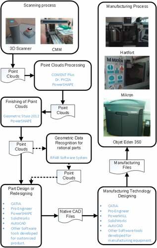
Several RE stages required to be conducted by engineers in the new product innovation stage in order to compete in the market include digitizing physical or clay models by scanning, processing the scanned data in .stl or mesh format, re-designing the physical model into a new product, New 3D CAD model design, CAM optimization, NC code creation, and manufacturing using CNC machines to obtain products (Anggoro et al., Citation2015; Anggoro, Yuniarto et al., Citation2019; Bagci, Citation2009). Meanwhile, RE process automation is known as Computer-Aided Reverse Engineering (CARE) in literature and is related to the Computer-Aided Engineering (CAE) which was applied as a Forward Engineering by (Vinesh & Kiran, Citation2008). The CAE process, however, involves the implementation of CAD, CAPP, and CAM technologies which are usually used in forward engineering which involves the starting of a project with an idea and the application of a complex manufacturing system to acquire new products through specific software and manufacturing equipment. An overview of the CARE system architecture according to (Bagci, Citation2009; Oancea et al., Citation2013) is, therefore, presented in .
Figure 1. The Architecture of CARE System.
This study was conducted to investigate the formation of Miranda Kerr Tea for One Teapot tableware ceramic products in PT Doulton Indonesia using the RE method in order to match consumer demand abroad. The physical models presented include products already placed in the market and observed to have complied with consumer standards. This means the inability of the new product to match the quality of the sample product would lead to an increment in product development time and costs and this is detrimental to the factory.
The RE technique was applied using 3D scanning devices such as coordinate measuring machines (CMM), laser scanners (3d scanners), structured light digitizers, and computer tomographers to quickly capture 3D data into digital form from the physical model. Meanwhile, the conventional measurement involved the comparison of the dimensions of the scans made by researchers and engineers in PT Doulton with the 2D images from a ceramic factory in China. Moreover, a 3D CAD drawing with the same dimensions and profile as the physical model was required in order to satisfy the consumer standards, company goals, and also to meet market demand. The goal of this research was to achieve flexibility in the supply chain and this was based on the question that “how can PT Doulton significantly reduce design time, geometry, and shape of the new product in line with market demand and towards ensuring mass production?”
A step in the process of converting a product on the market into 3D CAD data using a 3D scanner and the Coordinate Measurement Machine (CMM) was demonstrated in this study. The output was, however, in the form of 3D meshes which were further processed into 3D CAD model data using the RE method in the PowerSHAPE 2017 software. It is important to note that the process made use of a post-processor installed on the CNC milling machine. Meanwhile, the RE method was not used to redesign a product in this paper but to obtain the physical model profile geometry data was later redrawn using PowerSHAPE CAD. It is also possible to repair or change the profiles of the 3D meshes and point cloud data obtained from the sample products. Moreover, the RE results were in the form of a 3D CAD model for the Miranda Kerr Tea for One Teapot which was later transformed into a core and cavity mold table to be manufactured using the CNC milling machine. The final evaluation was made by comparing the geometry and shape of the product design for physical model, CAD model, mold base construction, and Miranda Kerr Tea for One Teapot product at a maximum dimension error of 3.00 mm.
2. Materials and method
The initial data needed in the product development process of Miranda Kerr Tea for One Teapot include the technical drawings in the 2D format as indicated in and the product samples already in the market as shown in . The problem observed at this stage was the difference in the information for the technical drawing and product sample in terms of dimensions and profiles as highlighted in . This produced an average difference of 4.00 mm and was discovered to have a bad impact on the company in fulfilling foreign customer demand which was pegged at a maximum design difference of 2.00 mm.
Figure 2. 2D/3D CAD model [source PT Doulton Indonesia]
![Figure 2. 2D/3D CAD model [source PT Doulton Indonesia]](/cms/asset/8457e209-1e9b-4b72-a913-893ee35469f3/oaen_a_1981522_f0002_b.gif)
Figure 3. Sample product on the market
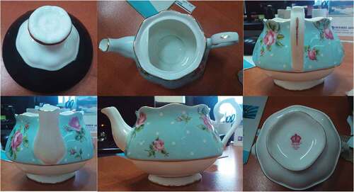
Table 1. Dimensions and errors for miranda kerr tea for one teapot
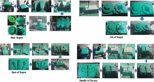
The application of RE in this research was, however, required to solve this problem. The process, therefore, involved subjecting the sample product to a scanning process using CMM scanning tools and 3D Scan Studio HD to produce image data with 3D mesh format as indicated in . Moreover, the parts of the body and lid without knob scanned was divided into 4 components which are the handle, base, lid, and spot for the RE and manufacturing process of Miranda Kerr Tea for One Teapot products to match the sample product in terms of size and shape as indicated in .
Figure 4. Stages of the physical model scanning process with output in the form of an image in a 3D mesh format
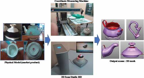
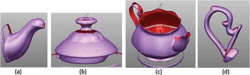
Figure 5. The four-component Miranda Kerr Tea for One Teapot scans: (a) spot; (b) lib; (c) base; (d) handle
was used to conduct the RE process needed to make the Miranda Kerr Tea for One Teapot product components into 3D CAD fire size, drawing, model size, and milling process as indicated in respectively.
Figure 6. 3D CAD fire size Miranda Kerr Tea for One Teapot: (a) spot; (b) lib; (c) base; (d) handle
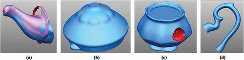
Figure 7. 3D CAD model size Miranda Kerr Tea for One Teapot with contraction 11.75% and an increase in height of 1.50 mm
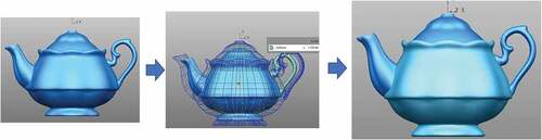
Figure 8. 3D CAD model Miranda Kerr Tea for One Teapot
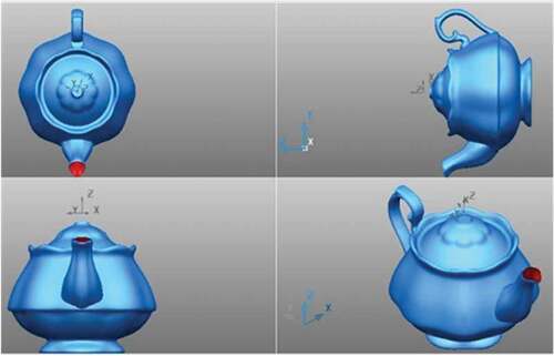
Figure 9. 3D CAD model milling process Miranda Kerr Tea for One Teapot: (a) spot; (b) lib; (c) base; (d) handle
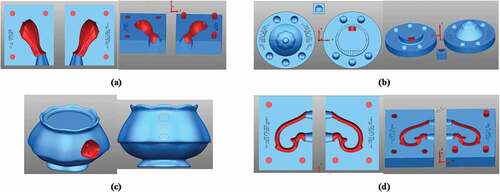
The final dimensions of the 3D CAD product are presented in . It is also important to note that a CNC milling machine with the YCM EV 1020A and CAM PowerMill2016 brands were applied in manufacturing the components to form the Miranda Kerr Tea for One Teapot product in the form of a core and cavity mold as shown in . The material used was a synthetic green hard Ebalta wood intended to be a raw material for molding in the ceramic industry. The machining results are, however, presented in while the final ceramic products are shown in .
Table 2. Comparison of dimensions between sample products, 3D Mesh and 3D CAD after RE miranda kerr tea for one teapot
3. Results and Discussion
The initial information used in the development of the teapot consist of the product samples and technical drawings and comparisons were made by measuring the dimensions of the product samples using a digital caliper with an accuracy of 0.01 mm including the height, length, width, and diameter on the body and lid of the teapot. The results of the measurements made for the sample products and technical drawings before and after RE are presented in respectively. It was, therefore, discovered that the 2D CAD dimensions or trial results required to pass the QC test for teapot products need to be within ± 2 mm for the product sample and the market sample. showed the difference in dimensions in the error section is above 2 mm and this means the main information obtained from the redesign process could be used later to produce samples or ideal pieces to suit market conditions and consumer desires. Meanwhile, the error after the RE has an average difference value below ± 1.00 mm in the 3D CAD Fire Size dimension as indicated in and this means the model designed based on RE using the sample products scanned beforehand was precise and in line with the market demand. The 2D/3D CAD model produced by CAD engineer PT Doulton based on the results of previous research (Anggoro et al., Citation2015, Citation2018; Anggoro, Tauviqirrahman et al., Citation2019; Xia, Citation2014; Ye et al., Citation2004) is, therefore, presented in . However, all the dimensions shown in give a dimension error of more than 3.00 mm () and this is not following the standards set by PT Doulton. This resulted in the need for further action by the authors and PT Doulton to resolve this case through the use of the CARE System technology so that the dimensional error obtained from the resulting Teapot product was less than 2.00 mm and it was proven that after the RE process was carried out the error value became less of 1.00 mm ().
The physical model scanned was a sample product of Miranda Kerr Tea for One Teapot made from Bone China clay material. It was already in the form of a decorated post and this means a finished product was scanned as shown in . This process was followed by the use of Engine 3D Scanner to retrieve relief data or embossed gloss of sample products as presented in with the focus on the spout, base, handle, and lid. The results from the scanning process were stored in stl format which is 3D Meshes as indicated in after which the priXa 1588 CMM was applied to retrieve geometry data or product profile samples such as foot and top sections on the base, lib diameter, and others as presented in . This process was conducted due to the shortcoming observed in the top and foot of the 3D mesh results in the form of a depth dimension during the scanning of the body, thereby, leading to the need to re-scan horizontally using the PriXa 1588 CMM. Moreover, the 3D Meshes on the lid were read perfectly as previously observed in (López et al., Citation2014; Majstorovic et al., Citation2013; Oancea et al., Citation2013; Vinesh & Kiran, Citation2008) . The relief data and geometry on the finished product after it has been burnt in the kiln and glazing led to the editing process using PowerSHAPE to produce 3D CAD data in the form of fire size. This was later converted into a model size as shown in , and .
shows a 3D image of a fire size model from Miranda Kerr Tea for One Teapot which is divided into four components, namely: spot; libs; bases; and handles are done using CAD PowerSHAPE software. Meanwhile, after obtaining the fire size model, a size model is then made so that the size of the Miranda Kerr Tea for One Teapot model is close to the sample product being scanned. At this stage, a contraction of 11.75% was carried out according to the advice of the PT Doulton engineer so that the designed model approached the physical model ( and ). The results of displaying the model in multiple isometric 3D views in PowerSHAPE can be seen in .
Figure 10. Core and cavity mold from miranda kerr tea for one teapot: (a) spot; (b) lib; (c) base; (d) handle
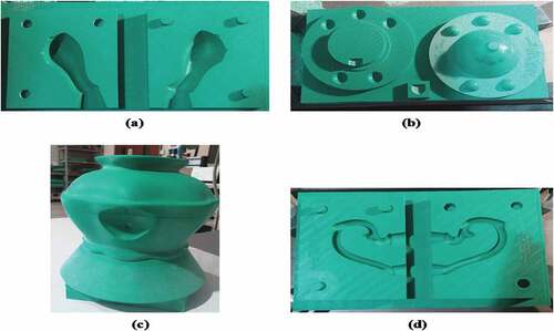
Figure 11. Product miranda kerr tea for one teapot [source: pt doulton indonesia dan PT nuanza porcelain indonesia]
![Figure 11. Product miranda kerr tea for one teapot [source: pt doulton indonesia dan PT nuanza porcelain indonesia]](/cms/asset/db171ee5-59f3-46a1-850e-9c37e4c20da5/oaen_a_1981522_f0011_oc.jpg)
Figure 12. 3D CAD Fire Size spot
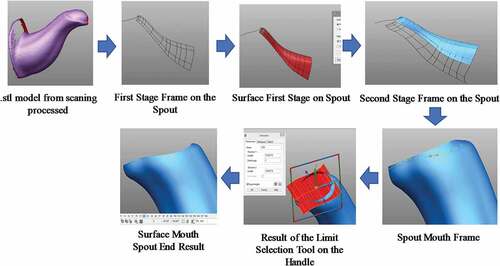
Figure 13. 3D CAD Fire Size lib
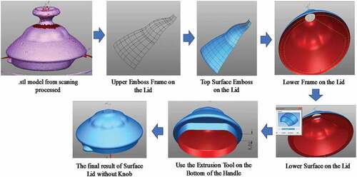
Figure 14. 3D CAD Fire Size handle
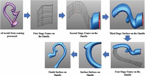
Figure 15. 3D CAD Fire Size base
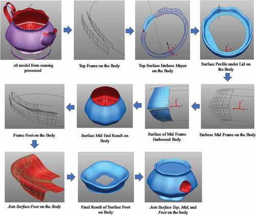
Figure 16. The process of transforming a 3D CAD model from fire size to model size
3.1. Analysis of making 3D CAD Fire size
Fire size is a 3D CAD data product with dimensions observed to be in accordance with the ideal size of the pieces or sample products. In this study, the 3D CAD data dimensions for the Miranda Kerr Tea for One Teapot need to approach the values for the sample product as presented in . Broadly speaking, the construction of the fire size data starts from building a frame consisting of lines or curves obtained from line processing to generate the frame surface. Meanwhile, the Miranda Kerr Tea for One Teapot has a symmetrical shape with eight major-minor embosses and this means only a part of the surface needed to be built and reproduced through rotate copy or mirror as many as the number of the embossed. The finishing aspect, however, involves the combination of each surface to become united towards simplifying the 3D CAM data production and the process of measuring the final dimensions needed to approach the values for the sample product. Furthermore, the details of the stages involved in the production of the 3D CAD Fire Size for the four components of the product are presented in . It is, therefore, possible to use the results from these stages as a reference for CAD engineers in the ceramic industry in implementing RE in teapot type ceramic products as also successfully applied by previous researchers in the insole, body implant, part machine, and other products in different industries (Andrei et al., Citation2015; Anggoro et al., Citation2017, Citation2018; Anggoro, Tauviqirrahman et al., Citation2019; Anggoro, Yuniarto et al., Citation2019; Babu & Thumbanga, Citation2011; Feng et al., Citation2014; Fergiawan et al., Citation2019; Huson & Hoskins, Citation2014; Hussain et al., Citation2008; López et al., Citation2014; Wang, Citation2008). The scanning output in .stl format was, however, generally converted by line processing to the surface and solid modeling in the CAD software used by the CAD researchers or engineers in the manufacturing industry (Anggoro et al., Citation2017; Babu & Thumbanga, Citation2011; Huson & Hoskins, Citation2014; Hussain et al., Citation2008; López et al., Citation2014; Sokovic & Kopac, Citation2005; Wang, Citation2008).
The final result of the four components in is precisely sized using the 3D mesh scanning model and this is evident with the absolute precision of 3D CAD Fire size as shown in and the 3D mesh scanning results with an error lesser than ± 1.00 mm as indicated in . This procedure has also been successfully used by (Anggoro et al., Citation2015; Anggoro, Yuniarto et al., Citation2019) in the CARE System application to design and fabricate tableware ceramic products and Islamic tile walls with floral patterns on Al Huda Mosque.
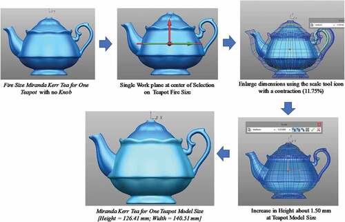
3.2. Analysis of making 3D CAD model size
The model size is the product’s 3D CAD data with dimensions scaled according to the percentage of the clay contraction. In ceramics, burned clay usually experiences shrinkage due to the evaporation of its water content which further leads to a reduction in its size, and this process is known as the contraction. It is, therefore, necessary to increase the dimensions depending on the clay contraction value to be used and the combustion method in the production section in order to ensure they are close to those of the product sample after shrinkage.
The fire size was changed to the model size using the scale tool in the PowerSHAPE or other software CAD as previously conducted by (Anggoro et al., Citation2015; Anggoro, Yuniarto et al., Citation2019; Fergiawan et al., Citation2019; Ye et al., Citation2004). The Miranda Kerr Tea for One Teapot was burned in a free-standing position with the base, handle, and spout becoming one body while the lid was placed on top. This, therefore, means the dimensions of both the body and lid were enlarged simultaneously. This 3D CAD Model design process has been done by the authors in this paper is presented in .
3.3. Contraction percentage of bone china material
Materials (clay) used in the ceramic industry have different percentages of contraction. The terms used in the modeling process at PT. Doulton is fire size and model size. Fire size is 3D CAD data with dimensions following the sample product size or finish product (glost). The model size is 3D CAD data of the product with dimensions scaled by the percent clay contraction set by the company ( and ). In ceramics, the burned clay shrinks because the water content in it evaporates so that the size becomes smaller, the amount of shrinkage is called contraction. Thus, it is necessary to enlarge the dimensions depending on the contraction value of the clay to be used and the combustion method in the production section. It is expected that after shrinkage, the dimensions are close to the product sample (physical model scanned in and ).
Changing the fire size to a model size is done using the scale tool in the PowerSHAPE software. Miranda Kerr Tea for One Teapot is burned in a free-standing position where the base, handle and spout become one (body) with the lid placed on top. Thus, dimensional enlargement is carried out on the body and lid simultaneously.
In the ceramic industry, the burned clay shrinks because the water content in it evaporates so that the product size becomes smaller and harder which is called contraction so that the dimensions are enlarged. The purpose of this dimension enlargement is so that the clay that is burned and shrinks and has the same dimensions as the expected fire size.
The case of RE product Miranda Kerr Tea for One Teapot in this paper uses Bone China clay and the authors set a contraction value of 11.75% (). This value was obtained based on information from the PT Doulton Indonesia engineer at the Slip House Department who is responsible for determining the percentage value of the clay contraction used. The contraction percentage value of 11.75% is then used by the authors to enter the number that must be inputted on the scale icon in CAD PowerShape so that the dimensions of the Teapot will be enlarged (Height, Length, and Width). The magnification of the dimensions of the Teapot from the Body and Lid with no Knob can be seen from with the dimensional error after the RE process obtained on average less than 1.00 mm ().
3.4. Analysis of making 3D CAD milling settings
3D CAD data needed to be edited before adjusting the machine to be used in creating the 3D CAM data. The machines used were CNC YCM 1020 EV20A (4-axis) as indicated in . The editing process was, however, conducted on each part of the teapot to produce a prototype in the form of a model for the base, mold for handle and spout, and the case for the lid.
Figure 17. YCM 1020 EV20A CNC machine
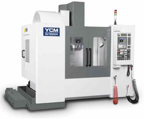
The production of plaster molds for base and spout involves a cast-on method which makes the mold for the base and spout become one while the machining process is separated due to the engine capability as observed from the meeting feasibility. This issue was, however, resolved by using a kind of slot for the meeting point between the base and spout to ensure the two components are combined after the completion of the machining process and before the transfer to the plaster mold manufacturing process. Meanwhile, the method applied for the base and handle is stuck-on and this involves using a separate mold for each of them after which they were later attached in the clay production process using a special glue. This means the base section was only marked using a line on the 3D CAD data as the place where the handle is attached. The stages of the CAM process and CNC manufacturing output are, however, presented in . At this stage, the CAM PowerMill software was used to obtain a toolpath strategy and working simulation in an optimal 3D CAD component model milling setting until a CNC machine was able to read the NC Code. This Code was used to move the milling cutter based on the contour and relief shape of the body, lib, spot, and handle components according to the toolpath strategy selected and used in this study. Moreover, several machining parameters such as cutting tools, rpm, step over, toolpath strategy, step down, lin, and link have also been selected by previous researchers (Anggoro et al., Citation2015, Citation2018; Anggoro, Tauviqirrahman et al., Citation2019; Anggoro, Yuniarto et al., Citation2019; Fergiawan et al., Citation2019). It is also important to note that the YCM 1020 EV20A is a 3–4 axis manufacturing industry standard CNC machine widely used in Indonesia.
Figure 18. CAM process stages of component miranda kear tea pot
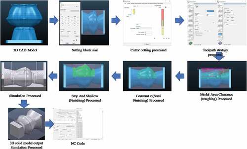
Figure 19. Stages of the manufacturing process in a CNC machine for all the components of miranda kerr tea for one teapot
The output of the CNC Milling machining process presented in was obtained through the activities of the PT Doulton operation. This involved pouring the liquid clay material into the mold to form a solid clay which was later made to pass through a kiln process in the combustion oven. The results obtained from the casting process based on the RE of the Miranda Kerr Tea for One Teapot product are, therefore, presented in several forms in . The RE stages implemented in developing the new ceramic tableware products were based on the variation in market demand as well as the influence of supply chain flexibility due to consumer demand which is beyond the capacity limit of foreign ceramic companies such as those in China.
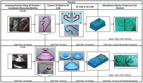
An overview of the successful RE application in the Miranda Kerr Tea for One Teapot product is presented in with the total production time recorded to be 43 hours 18 minutes 10 seconds at a total cost of approximately $ 4172.35. In , the authors also show a detailed sequence of steps from the RE process until the master product Miranda Kerr Tea for One Teapot is obtained from the four components (body, spout, handle, and cover). At each stage is also displayed the total time worked by the authors in producing output at each stage, so that this can be used by CAD engineers in ceramic companies or other researchers in carrying out the RE process with CARE System technology.
Figure 20. RE from 3D mesh to master product body and spot for miranda kerr tea for one teapot.
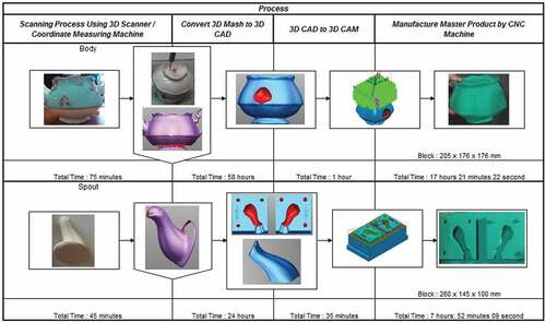
Figure 21. RE from 3D mesh to master product handle and lib for miranda kerr tea for one teapot.
The processes applied by the engineers and researchers were observed to be in line with the findings of several previous studies (Andrei et al., Citation2015; Ashima et al., Citation2021; Fatima et al., Citation2021; Feng et al., Citation2014; Haleem & Javaid, Citation2020; Ul Haq et al., Citation2020; Huson & Hoskins, Citation2014; Javaid & Haleem, Citation2018a, Citation2020; Kucklick, Citation2006) that have used RE to meet market demand through fast, precise, and accurate products.
4. Conclusion
Reverse Engineering process using CARE System technology was successfully applied to Miranda Kerr Tea for One Teapot products to improve supply chain flexibility. The purpose was to make it possible for researchers and engineers in PT Doulton to develop new RE-based products according to variations and immediate market demands. This is observed to be necessary considering the inability of the ceramic company in China to meet consumer demand due to limited capacity.
The process, however, involved measuring product samples, scanning processes, making 3D CAD data, and making 3D CAM data as well as manufacturing on a CNC milling machine to determine the difference between dimensions of the 3D CAD and product samples which was recorded to be below 1 mm. This, therefore, means the quality of the design and printed products are precise, accurate, and fin line with the physical model.
More in-depth research is, however, needed in the future on the application of Reverse Engineering to the use of Coordinate Measuring Machines for other ceramic products towards ensuring supply chain flexibility, especially for other local ceramic factories in Indonesia in order to increase their competitive advantage in the global market. This CARE system is expected to solve the design, manufacturing, and fabrication problems faced by the National Ceramic Industry in Indonesia to develop other ceramic products (tableware, tile wall, toys, 3d paint wall, jewelry).
Acknowledgements
The authors appreciate Ririn Diar Astanti, D.Eng, Head of Department Industrial Engineering Program, Faculty of Industrial Technology, University of Atma Jaya Yogyakarta, the University of Diponegoro in Semarang, PT Doulton Indonesia, PT Nuanza Porcelain Indonesia, and PT. Hankook Delcam Indonesia for providing full support in the form of infrastructures such as CAM, CAD, and RE needed during the design, development, and writing of this research work.
Disclosure statement
No potential conflict of interest was reported by the author(s).
Additional information
Funding
Notes on contributors
P.W. Anggoro
P.W. Anggoro obtained a doctoral degree from Universitas Diponegoro, Indonesia and Lecture at Department of Industrial Engineering, Universitas Atma Jaya Yogyakarta, Indonesia. His research interest focus on Reverse Innovative Design with additive and subtractive manufacturing technology. Tan Wijaya, received a BS degree in engineering from the Universitas Atma Jaya Yogyakarta. T. Yuniarto obtained a master’s degree from Universitas Gajah Mada, Indonesia. M. Tauviqirrahman obtained a doctoral degree from the Laboratory for Surface Technology and Tribology, University of Twente, the Netherlands. J. Jamari is a professor in tribology and received a doctoral degree from the Laboratory for Surface Technology and Tribology, University of Twente, the Netherlands. Athanasius P. Bayuseno is a professor in material science and engineering and a Senior Lecturer in the Mechanical Engineering Department of Universitas Diponegoro, Indonesia. Djoko Budiyanto Setyohadi is a professor in the system information of the Department of Universitas Atma Jaya Yogyakarta.
References
- Andrei, P., Andrei, A., & Adrian, P. (2015). Reverse engineering technique applied for manufacturing thin wall plastic parts. Applied Mechanics and Materials, 772, 212–20. http://dx.doi.org/10.4028/www.scientific.net/AMM.772.212
- Anggoro, P. W., Anthony, A. A., Bawono, B., Jamari, B. A. P., Tauviqirrahman, M., & Nugroho, A. (2019). CNC milling of EVA foam with varying hardness for custom orthotic shoe insoles and process parameter optimization. Journal of Mechanical Engineering and Sciences, 13(3), 5347–5370. https://doi.org/10.15282/jmes.13.3.2019.10.0436
- Anggoro, P. W., Bawono, B., & Sujatmiko, I. (2015). Reverse engineering technology in redesign process ceramics: Application for CNN plate. Procedia Manufacturing, 4, 521–527. https://doi.org/10.1016/j.promfg.2015.11.071
- Anggoro, P. W., Bawono, B., Tauviqirrahman, M., Jamari, J., & Bayuseno, A. P. (2019). Design and manufacturing insole shoes orthotic for optimal surface roughness using CNC milling machine. Journal of Engineering Science and Technology, 14(4), 1799–1819.
- Anggoro, P. W., Saputra, E., Tauviqirrahman, M., Jamari, J., & Bayuseno, A. P. (2017). A 3dimensional finite element analysis of the insole shoe orthotic for foot deformities. International Journal of Applied Engineering Research, 12(15), 5254–5260.
- Anggoro, P. W., Tauviqirrahman, M., Jamari, J., Bayuseno, A. P., Bawono, B., & Avellina, M. M. (2018). Computer aided reverse engineering system in the design and production of orthotic insole shoes for patients with diabetes. Cogent Engineering, 5(1), 1–20. https://doi.org/10.1080/23311916.2018.1470916
- Anggoro, P. W., Tauviqirrahman, M., Jamari, J., Bayuseno, A. P., Wibowo, J., & Saputro, Y. D. (2019). Optimal design ang fabrication of shoe last for ankle foot orthotics for patients with diabetes. international journal of manufacturing. Material and Mechanical Engineering (IJMMME), 9(2), 64–78. http://doi.org/10.4018/ijmmme.2019040104
- Anggoro, P. W., Yuniarto, T., Tauviqirrahman, M., Jamari, J., Bayuseno, A. P., Purwanto, K. B., & Widyanarka, O. K. W. (2019). Puzzle islamic floral patterns product tiles for wall and ceiling to decorate of al huda mosque indonesia—design, manufacturing, and fabrication. Proceeding of 6th internasional conference and exhibition on sustainable energy and advanced materials, ICE-SEAM 2019, 16-17 October 2019, surakarta, indonesia, lecture note in mechanical engineering.
- Ashima, R., Haleem, A., Bahl, S., Javaid, M., Mahla, S. K., & Singh, S. (2021). Automation and manufacturing of smart materials in additive manufacturing technologies using Internet of Things towards the adoption of industry 4.0. Materials Today: Proceedings, 45, 5081–5088. https://doi.org/10.1016/j.matpr.2021.01.58
- Babu, T. S., & Thumbanga, R. D. (2011). Reverse Engineering CAD/CAM & pattern less process applications in casting-A case study. International Journal of Mechanics, 5, 40–47. https://www.naun.org/main/NAUN/mechanics/20-092.pdf
- Bagci, E. (2009). Reverse engineering applications for recovery of broken or worn parts and re-manufacturing: Three case studies. Advances in Engineering Software, 40(6), 407–418. https://doi.org/10.1016/j.advengsoft.2008.07.003
- Fatima, S., Haleem, A., Bahl, S., Javaid, M., Mahla, S. K., & Singh, S. (2021). Exploring the significant applications of Internet of Things (IoT) with 3D printing using advanced materials in medical field. Materials Today: Proceedings, 45, 4844–4851. https://doi.org/10.1016/j.matpr.2021.01.305
- Feng, L., Longstaff, A. P., Fletcher, S., & Myers, A. (2014). Rapid and accurate reverse engineering of geometry based on a multi-sensor system. The International Journal, Advanced Manufacturing Technology, 74(1–4), 369–382. https://doi.org/10.1007/s00170-014-5997-y
- Fergiawan, P. K., Anggoro, P. W., Yuniarto, T., Purwanto, K. B., & Widyanarka, O. K. W. (2019). Ceramic jewelry with texture and ornament islamic pattern and batik indonesia – design, manufacturing, and fabrication. Proceeding of 6th International Conference and exhibition on sustainable energy and advanced materials, ICE-SEAM 2019, 16-17 October 2019, surakarta, indonesia, lecture note in mechanical engineering.
- Haleem, A., & Javaid, M. (2019a). 3D scanning applications in medical field: A literature-based review. Clinical Epidemiology and Global Health, 7(2), 199–210. https://doi.org/10.1016/j.cegh.2018.05.006
- Haleem, A., & Javaid, M. (2019b). Polyether ether ketone (PEEK) and its 3D printed implants applications in medical field: An overview. Clinical Epidemiology and Global Health, 7(4), 571–577. https://doi.org/10.1016/j.cegh.2019.01.003
- Haleem, A., & Javaid, M. (2020). 3D printed medical parts with different materials using additive manufacturing. Clinical Epidemiology and Global Health, 8(1), 215–223. https://doi.org/10.1016/j.cegh.2019.08.002
- Haleem, A., Javaid, M., Khan, R. H., & Suman, R. (2020). 3D printing applications in bone tissue engineering. Journal of Clinical Orthopaedics and Trauma; 11: S118eS124, 11, S118–S124. https://doi.org/10.1016/j.jcot.2019.12.002
- Huson, D., & Hoskins, S. (2014). 3D printed ceramics for tableware, artists/designers and specialist application. Centre for Fine Print Research, University of the West of England. Switzerland: Trans Tech Publications. https://doi.org/10.4028/www.scientific.net/KEM.608.351
- Hussain, M. M., Sambasiva Rao, C. H., & Prasad, K. E. (2008). Reverse engineering: Point cloud generation with CMM for part modeling and error analysis. ARPN Journal of Engineering and Applied Sciences, 3(4), 37–40. http://www.arpnjournals.com/jeas/research_papers/rp_2008/jeas_0808_113.pdf
- Javaid, M., & Haleem, A. (2018a). Additive manufacturing applications in orthopaedics: A review. Journal of Clinical Orthopaedics and Trauma, 9(3), 202–206. https://doi.org/10.1016/j.jcot.2018.04.008
- Javaid, M., & Haleem, A. (2018b). Additive manufacturing applications in medical cases: A literature based review. Alexandria Journal of Medicine, 54(4), 411–422. https://doi.org/10.1016/j.ajme.2017.09.003
- Javaid, M., & Haleem, A. (2020). 3D printed tissue and organ using additive manufacturing: An overview. Clinical Epidemiology and Global Health, 8(2), 586–594. https://doi.org/10.1016/j.cegh.2019.12.008
- Javaida, M., & Hal, A. (2019). Current status and applications of additive manufacturing in dentistry: A literature-based review. Journal of Oral Biology and Craniofacial Research, 9(3), 179–185. https://doi.org/10.1016/j.jobcr.2019.04.004
- Kucklick, T. (2006). Reverse engineering in medical device design . The Medical Device R&D Handbook;.
- López, C. I., Pinillos, J. C., & Juan, C. (2014). Moreno. Comparison between two design methods implants, based on reverse engineering, design and engineering technologies, BIOCAD/CAD/CAE. Ingeniería y Competitividad, 16(1), 61–68. https://www.researchgate.net/publication/317499786_Comparison_between_two_design_methods_implants_based_on_reverse_engineering_design_and_engineering_technologies_BIOCADCADCAE
- Majstorovic, V., Trajanovic, V., Vitkovic, N., & Stojkovic, M. (2013). Reverse engineering of human bones by using method of anatomical features. CIRP Annals – Manufacturing Technology, 62(1), 167–170. https://doi.org/10.1016/j.cirp.2013.03.081
- Oancea, G., Ivan, N. V., & Pescaru, R. (2013). Computer aided reverse engineering system used for customized products. Annals of MTeM for 2013 & Proceedings of the 11th International MTeM Conference Published by MTeM 2013, Cluj-Napoca, Romania, Editor N. Bâlc. THE 11th INTERNATIONAL MTeM CONFERENCE, 17th −19th OCTOBER 2013. Pp 181–186.
- Singare, S., Dichen, L., Bingheng, L., Yanpu, L., Zhenyu, G., & Yaxiong, L. (2004). Design and fabrication of custom mandible titanium tray based on rapid prototyping. Medical Engineering & Physics, 26(8), 671–676. https://doi.org/10.1016/j.medengphy.2004.06.001
- Sokovic, M., & Kopac, J. (2005). RE (reverse engineering) as necessary phase by rapid product development. Journal of Materials Processing Technology, 175(1–3), 398–403. https://doi.org/10.1016/j.jmatprotec.2005.04.047
- Ul Haq, M. I., Khuroo, S., Raina, A., Khajuria, S., Javaid, M., Ul Haq, M. F., & Haleem, A. (2020). 3D printing for development of medical equipment amidst coronavirus (COVID-19) pandemic—review and advancements. Research on Biomedical. Engineering. Published on line” 1 October. https://doi.org/10.1007/s42600-020-00098-0
- Vinesh, R., & Kiran, F. J. (2008). Reverse engineering – An industrial perspective (V. Raja & K. J. Fernandes, Eds.). London: Springer-Verlag.
- Wang, W. (2008). Application of reverse engineering in manufacturing industry. In Departement of engineering technology universitas of massachusetts lowell. MA, USA.
- Wego, W. (2010). Reverse Engineering: Technology of REinvention. CRC Press, Taylor & Francis;.
- Xia, Z. (2014). Application Of Reverse Engineering Based On Computer In Product Design. International Journal of Multimedia and Ubiquitous Engineering, 9(5), 343–354. https://doi.org/10.14257/ijmue.2014.9.5.35
- Ye, X. Z., Peng, W., Chen, Z. Y., & Cai, Y. Y. (2004). Today’s students, tomorrow’s engineers — An industrial perspective on cad education. Computer-Aided Design, 36(14), 1451–1460. https://doi.org/10.1016/j.cad.2003.11.006