
Abstract
In replacement surgery of the hip joint, an implant is replaced into the natural femur which recreates the articulation and functionally of a natural joint. Total hip replacement is significantly increasing by the day worldwide and is likely to increase by 174% by 2030. Primary revision is another major concern for total hip replacement with revision rates likely to increase by 137%. The first part of the article states the basic anatomy of the hip joint, different ligaments in the hip, the disorders associated with the joint, and evaluation of total hip arthroplasty. In the second part some of the major works are highlighted followed by a detailed discussion about different design considerations and wear-related issues in hip joints. More emphasis is given to the tribological behavior of implants under different conditions. The design aspects and several parameters which affect the wear rate in implants are summarized. Also, different testing methods which are used both in experimental and numerical techniques are reported to estimate the wear rates in hip implants with the evolution of hip implants since the early 20th century, in terms of different designs, materials and wear hip implant arthroplasty is known as one of the best advancements in healthcare. Further research is needed to establish to improve the life expectancy of hip implants.
PUBLIC INTEREST STATEMENT
Total hip replacement is significantly increasing day by day and is likely to increase by 174% by 2030. Primary revision is another major concern for total hip replacement with revision rates likely to increase by 137%. This review article gives an overview of the basic anatomy of the hip joint, different ligaments in the hip, the disorders associated with the joint, and evaluation of total hip arthroplasty. Wear is the predominant factor in the revision surgery of the hip implant. Previously many works are carried in both invitro and invivo to reduce the wear rate in the interferences of the hip implants. By reducing the wear rate the life expectancy of hip implants can be increased. Previously considered different designs and also the some of the major wear studies are discussed in detail. This work helps to know the previous works carried out and also the different designs which are used in the total hip replacement techniques.
1. Introduction
Hip joint replacement is considered to be among the greatest advances in medical science in the twentieth century (Courpied & Caton, Citation2011). From the early 17th century numerous efforts were made for hip replacements using materials such as silver plates, magnesium, zinc, glass, celluloid, decalcified bones, wax, etc. (Mellon et al., Citation2013). After two and half centuries, in the year 1948, the first femoral head prosthesis was used in clinical practice in France (Courpied & Caton, Citation2011). However, the major advancement of the hip joint prosthesis was in the year 1962 when Sir John Charnely designed a low frictional hip implant also called low frictional arthroplasty (LFA; Chethan, Satish Shenoy et al., Citation2018). This implant consisted of a 22.5 mm femoral head articulating over a polyethylene socket. He also predicted an average linear wear rate of 0.1 mm/year in this implant (Wroblewski et al., Citation1999). Currently, the surgical procedure for hip replacement has been standardized and the number of failures during the surgery has reduced significantly. Many in-vitro and in-vivo studies have been performed to estimate the life of hip implants (Lombardi et al., Citation2000; Damm et al., Citation2017; Komistek et al., Citation2002). The major problem associated with hip implant evaluation is the time required to perform the experiments in-vivo. However, the evolution of computational techniques greatly influenced the advancement of hip implants. The performance of implants that are subjected to loading conditions can be evaluated using the numerical approach (Darwich et al., Citation2019; Saxena et al., Citation2015). This also helps to modify the design and related parameters of the implants. Currently, there are several designs available with different material combinations. Due to the advancement in the computational approach, various studies have been carried out to evaluate the performance of the implants (Rymek & Ciszkiewicz, Citation2022; Levadnyi et al., Citation2021; Bashiri et al., Citation2020). FEM Studies have also been conducted to estimate the wear in the articulating surfaces of hip implants, and also to follow up on the implants which were retrieved after the revision surgery.
Even though the estimation of wear did match with that of the retrieved implants after the revision surgery, there were some limitations and assumptions which need to be considered during the analysis. The following sections present the overview of the FEA utility in investigating the structural behaviors of hip implants concerning its advances and some issues with the analysis.
The musculoskeletal system which comprises different muscles, bones, and ligaments gives support, stability, shape, and movement to the human body. The total number of bones in the skeletal system is 270 at birth and gradually reduces in number to 206 at adulthood due to the fusion of few bones (Chethan, Zuber, Bhat, et al., Citation2019a). The hip joint is amongst the largest of the weight-bearing joints after the knee () and one of the strongest joints.
Figure 1. The natural hip joint (right hip). (a) Capsule removed anterior aspect, (b) showing the ligament (Chethan, Shyamasunder Bhat et al., Citation2018; Mattei et al., Citation2011).
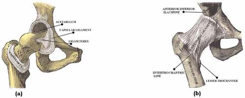
Usually, the average male femur is about 480 mm in length with a diameter of 23.4 mm (Nakabayashi et al., Citation1994; Chethan, Bhat et al., Citation2019; Portigliatti-Barbos et al., Citation1987). The hip joint is a classic example of a ball and socket joint where the head of the femur articulates in the acetabulum of the pelvis. The head of the femur and acetabulum are covered by a 63.5 mm thick shiny white hyaline which acts as a smooth cushion to the joint (Chethan, Shyamasunder Bhat et al., Citation2019). This joint has synovial fluid articulated in the mating surface which allows the joint to flex under different pressures without causing wear and tear. The synovial fluid and the hyaline help the bones move each other at different degrees of freedom without causing pain to the human.
1.1. Anatomy of hip joint
1.1.1. Proximal femur
The femur is the strongest and longest of the bones in the human body. It comprises of
Head
Neck
Two large projections—greater trochanter and lesser trochanters.
The proximal femur is depicted in .
Figure 2. (a) Anterior view (Putz & Pabst, Citation2006).
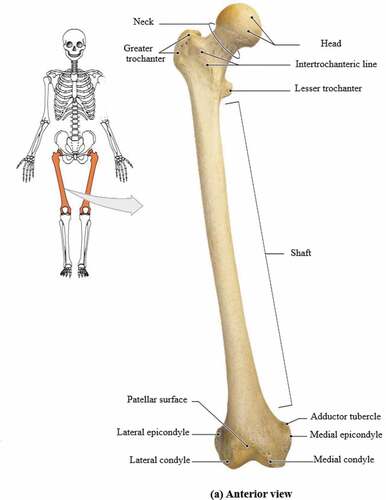
The femoral head is spherical and forms a joint with the acetabulum of the pelvis. The head is connected to the shaft of the femur at an angle of 125° as it projects from the shaft. The movement of the hip joint is relative to the orientation of the neck to the shaft.
1.1.2. Greater and lesser trochanters
The greater trochanter extends superiorly lateral to the junction between the shaft and neck of the femur as shown in . A deep groove is seen on the surface medial to the trochanteric fossa. The obturator externus muscle is attached to an oval depression on the lateral wall of the trochanteric fossa.
The lesser trochanter in is conical in shape and is smaller in size compared to the greater trochanter. It projects at a point lower to the junction between the shaft and neck of the femur. The intertrochanteric line and crest extend between the two trochanters and separate the shaft of the femur from the neck (Putz & Pabst, Citation2006).
1.1.3. Intertrochanteric line
The intertrochanteric line runs from the greater trochanter to the lesser trochanter anteriorly in the proximal end of the femur. It curves medially below the lesser trochanter and runs around the femoral shaft and merges with its medial margin to continue as the spiral line (Joint Structure and Function : Joint Structure and Function , Citation2005).
1.1.4. Intertrochanteric crest
The bony ridge seen between the greater and lesser trochanters posteriorly is known as the intertrochanteric crest. From the summit of the greater trochanter to the lesser trochanter the intertrochanteric crest stretches obliquely downward.
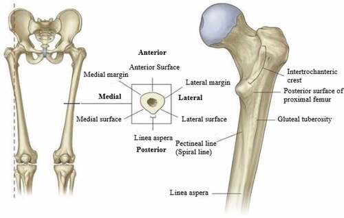
1.1.5. Shaft of the femur
In the coronal plane, the femoral shaft descends at an angle of 7° from laterally to medially in the vertical axis. Therefore, in the femur, the distal end is closer than the upper end of the shaft from the midline. The entire weight of the body is transmitted through the pelvis to the femur. The cross-section of the femur is shown in .
Figure 3. The shaft of the femur (Gray, Citation1960).
1.1.6. Acetabulum
The acetabulum is a cup-shaped structure, large in size, and articulates with the head of the femur. It is located on the lateral surface of the pelvic bone where the ilium and ischium fuse with the pubis (Gray, Citation1960). shows the cross-section of the acetabulum.
Figure 4. Acetabulum (Gray, Citation1960).
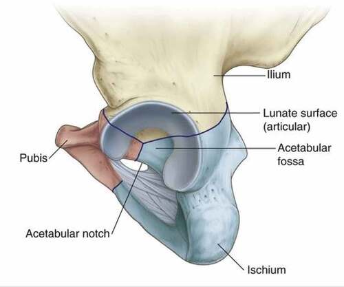
The acetabulum wall consists of non-articular and articular parts. The acetabulum fossa is a rough shallow circular cavity or depression which is the nonarticular portion continuous with the acetabulum notch. The margins of this fossa form the articular surfaces which are broad and are referred to as the anterior, posterior, and superior margins. The lunate surface is deficient inferiorly at the acetabular notch. The acetabular fossa provides attachment for the ligament of the femoral head. The blood vessels and nerves pass through the acetabular notch (Joint Structure and Function : Joint Structure and Function , Citation2005).
1.2. Cross-section of the femur
Figure 5. Cross-section of the femur (Gray, Citation1960; Izzo, Citation2012b).
The cross-sectional view of the femur is shown in . Nerves and blood vessels are packed in the thin outermost membrane and supply the cells of which the hard bone below is built. The next layer is the compact bone which is dense and rigid. It is cylindrical in shape has thousands of passages and tiny holes, through which blood vessels and nerves supply nutrients and oxygen to the bone. The dense bone that supports body weight is made up of calcium and minerals and feels no pain. However, the skin is sensitive, and thus when the bone is injured or broken, the nerve fibers that through the compact bone send pain signals to the brain.
1.3. Functions of hip joint
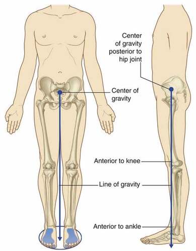
1.3.1. Bodyweight supports
With a minimum amount of energy, the primary function of the lower limb is to support the body weight. The vertical line through the center of gravity is slightly behind the hip joints and ahead of the knee and ankle joint. shows the center and line of gravity from the pelvis to the distal end of the human body.
Figure 6. Centre of gravity (Gray, Citation1960).
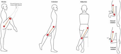
1.3.2. Locomotiontab
The movement of the body is due to the support from the lower limbs. Hip joints have the following degrees of freedom which include flexion, extension, abduction, adduction, internal rotation, external rotation which are six in number (Calais-Germain, Citation2004). These help to carry out activities of daily life which include walking, running, jogging, and climbing stairs. Various motions of the joint are mentioned in .
Table 1. Comparison between textbook references: Active Range of Motion of the Adult hip [in Degrees] (Roach & Miles, Citation1991; Sankar et al., Citation2012)
This range of motions may vary from person to person depending upon his lifestyle. shows the different motions associated with the joint.
Figure 7. Motions of the hip joint (Joumana Medlej, Citation2014).
When the articular lunate surface is damaged over the years due to age or trauma the joint experiences wear. These wear debris biologically react with the blood cells and the patient may experience severe pain which results in constrained joint movement. The hip joint is surrounded by muscles as well as ligaments and its stability depends on the deep insertion of the femoral head into the acetabulum. A ring of cartilage surrounds the acetabulum of the joint referred to as the acetabular labrum which tightly holds around the head of the femur. Attachment of the capsule is the acetabulum with labrum and transverse ligament that bridges the acetabular notch inferiorly. The capsule is connected anteriorly to the intertrochanteric line and posteriorly about 15 mm proximal to the intertrochanteric crest on the femoral side. Thus, most of the femoral neck is intracapsular.
1.4. Ligaments
Ligaments are the main structure in the human which helps to maintain the stability of the body. Ligaments prevent the bones from bending. Hip joint consists of the following ligaments.
Intracapsular ligaments
Extracapsular ligaments
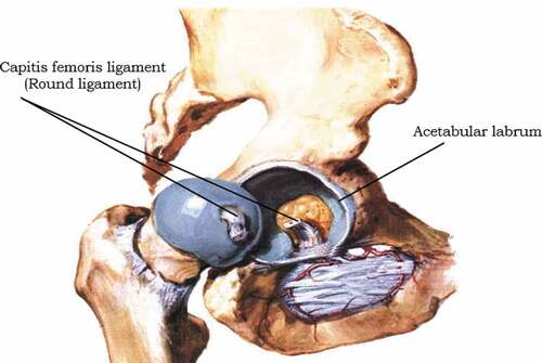
1.4.1. Intracapsular
An intracapsular ligament is a small structure that runs from the acetabular fossa to the fovea of the femur. It also encircles the obturator artery which is one of the branches of the blood vessel to the femoral head. The obturator artery provides a negligible arterial supply to the hip joint (Nam et al., Citation2011). shows the sagittal view of the right hip.
Figure 8. Sagittal view of the right hip (Izzo, Citation2012b; Izzo, Citation2012a).
1.4.2. Extracapsular
The hip joint has a strong fibrous capsule. It is strengthened by fibers that circularly pass around the joint.
In places the capsule is thickened to form 3 ligaments which are referred to, by their attachments, as
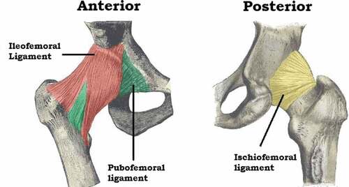
Iliofemoral ligament
Pubofemoral ligament
Ischiofemoral ligament (Navarro-Zarza et al., Citation2012).
1.4.2.1. Iliofemoral ligament
It extends from the ilium to the femur in the front of the joint. It is known as Y shaped Ligament due to its structure. It is the strongest ligament compared to the other two and other ligaments in the human body (Pal Singh, Citation2015). The iliofemoral ligament and the pubofemoral ligament are shown in ,
1.4.2.2. Pubofemoral ligament
It is also called a pubocapsular ligament. It is located on the inferior part of the hip joint and spreads from the pubic portion of the acetabular rim passing inferior to the neck of the femur.
1.4.2.3. Ischiofemoral ligament
It is a triangular band of strong fibers located on the posterior portion of the hip joint. The fibers are spiral in nature. Ischiofemoral ligament is also shown in figure 1.9,
1.5. Stabilizing factors
The primary function of a hip joint is weight-bearing mobility. Several factors affect the stability of the hip joint. The acetabulum is deep and covers nearly 80% of the femoral head. Thus, the chance of dislocation of the head out of the acetabulum is minimal. The fibrocartilaginous labrum around the acetabulum also helps to increase the depth of the acetabulum. This increase in depth helps to have a better articular surface and increases joint stability.
Ligaments around the joint are strong and furnish increased stability to the joint. shows the ligaments present in the hip joint. They have a distinct spiral orientation that tightens during the extension of the joint (Nam et al., Citation2011). Muscles as well as ligaments of the joint work in a reciprocal manner. Ligaments are stronger anteriorly and weaker posteriorly and thus the chances of dislocation are higher in a posterior direction.
Figure 9. Anterior and posterior view of the hip joint (Jones, Citation2019).
1.6. Common painful disorders: hip region
Usually, hip problems are associated with aged people due to worn-out hip joints. However, hip joint disorders can be associated with any person irrespective of age without proper care.
1.6.1. Osteoarthritis (OA)
Hip arthritis can cause pain in the groin or low buttock area radiating to the knee. It is one of the common problems in the hip due to the breakdown of the cartilage that cushions the ends of the bones where they meet to form joints. Osteoarthritis pain worsens with activity and diminishes or is absent with rest. A patient suffering from inflammatory arthritis can feel inactivity stiffness whereas movement of the hip joint may provide him with much-required relief. The pain can be relieved by replacements.
1.6.2. Rheumatoid arthritis (RA)
It is one of the chronic inflammatory diseases of the joints occurs due to the body’s own immune system attacking the synovium, a thin membrane that lines the joints.
1.6.3. Infectious arthritis
Infectious arthritis is referred to as septic arthritis which occurs due to infection within the joints. It is often caused by bacteria that spread through the bloodstream to the joint. In some cases, it is also caused due to fungi or viruses.
1.6.4. Avascular necrosis
Avascular necrosis is one of the common disorders in the hip joints. In avascular necrosis blood supply to the head of the femur is stopped which causes it to die and finally collapse.
1.6.5. Lupus
Lupus is an autoimmune disorder where the bone immune system creates antibodies that attack healthy tissues and damage them. Lupus can cause inflammation of joints as well as the heart, lungs skin, kidney.
1.6.6. Trochanteric Bursitis
Trochanteric Bursitis is an extremely common disorder caused due to trauma or excess physical activity viz running or jumping due to which the greater trochanteric bursa gets inflamed. The inflamed bursa gets sore due to the movements between the wider trochanter and the overlying iliotibial band. The patient experiences weight-bearing discomfort on one leg due to the tightening of the iliotibial band in an attempt to preserve the upright posture. The patient may also express an inability to lie on the affected side. Tenderness with over palpation on the wider trochanter and discomfort with avoided hip invasion is observed during physical examination. Nonsteroidal anti-inflammatory drugs, steroid injections are used to reduce the pain caused by trochanteric bursitis. Assistive devices like cane or crutches can also be used to avoid applying complete load on the hip during its healing.
1.6.7. Snapping hip (Coxa Saltans)
Younger patients may raise concerns regarding snapping or hip clicking. In such cases, the chances of dislocation of the hip are unlikely without considerable trauma or subsequent to arthroplasty of the hip joint. Intraarticular trauma or triggers external to the joint may induce cracking or clicking of the hip. Intraarticular conditions involve loose bodies (synovial chondromatosis, bone parts, broken-off osteophytes), labral tears, and, sometimes genuine subluxation of the hip joint, particularly after total hip replacement. Loose bodies could trigger intraarticular clicking which can be sporadic and illustrated through active and passive range of motions (ROM) research. Adduction with axial tension can lead to internal movement of the flexed hip and lead to pain in cases of a labral tear. Extraarticular factors are much more common; these involve dragging of the gluteus maximus muscle’s iliotibial band or fibers over the broader trochanter and sometimes snapping of the iliopsoas tendon over the head of the femur. Generalized laxity of the ligaments is typical among these individuals. By vigorous manipulation of the hand, the individual can often actively exhibit the cracking, and the resulting snapping or clicking can often be heard laterally over the wider trochanter as the iliotibial band clicks in and out. Medial clicking of the iliopsoas tendon, noticeable, and sometimes audible is demonstrated through aggressive flexion of the hip and lateral rotation with a successful extension of the hip (Spina, Citation2007).
1.6.8. Periarticular fracture
Hip fracture due to fall in elderly can cause hip fracture resulting in severe pain and inability to bear weight and walk. In elderly patients, a sudden fall may cause hip pain either by soft tissue damage or undisplaced sub-capital hip fractures. Radiographs and CT scans are used to diagnose this type of injury. Occasionally it is reported that the patients can continue to walk with an impacted fractured hip for days before diagnosis.
2. Hip implants and their evaluations
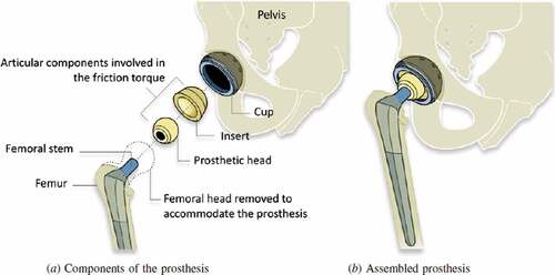
Hip replacement surgery is considered to be amongst the greatest advances in health care of the twentieth century. In 1925 the first replacement made out of glass was used for the surgery by an American surgeon Marius Smith-Petersen (Knight et al., Citation2011). An American surgeon named Dr. Austin T. Moore at the Columbia Hospital, South Carolina performed the first metallic hip replacement surgery on 28 September 1940 (Chillag, Citation2016). Later, Sir John Charnley, who is considered the father of modern total hip arthroplasty, modeled a low friction arthroplasty in the early 1960s (Gomez & Morcuende, Citation2005; Jackson, Citation2011). This design was identical, in principle, to the prosthesis used in the present day. It consisted of a stem and head of the femur and an acetabular cup with a backing cup (Knight et al., Citation2011). These components of hip implants are available in different designs and sizes. The femoral head is usually selected based on the anatomy of the patient. It could vary from 22 to 54 mm depending on the age, sex, and anatomy of each individual (Hammerberg et al., Citation2010; Cross et al., Citation2012). Different materials which included stainless steel, alumina, zirconia, alloys of titanium and cobalt-chromium (Co-Cr) alloys, Ultrahigh molecular weight polyethylene (UHMWPE), High crosslinked UHMWPE (XLPE) may be used for the hip implants (Hu & Yoon, Citation2018). These materials are combined as metal on metal (MoM), metal on polyethylene (MoP), Ceramic on polyethylene (CoPE), Ceramic on Ceramic (CoC) Ceramic-on-metal (CoM), with each material exhibiting different properties. The shows the components used in hip implants.
Figure 10. Schematic diagram of a total hip replacement, indicating the different components (Grandjean et al., Citation2012).
2.1. Issues associated with implant implementation during surgery
Surgery of the hip joints is a complicated procedure that requires precautions during and post-surgery. With the aid of CT scans the surgeons decide the type and design of the implant to be used as well as the size of the head of the femur and backing cup. Post-surgical infections and blood clots are some of the complications associated with arthroplasty. Change in the length of the legs after surgery is another problem associated if the implants are not of the appropriate dimension. If these parameters are not addressed appropriately it could lead to an increase in hip pain than relieving pain after the surgery. Loosening of the hip joint is a major reason for revision surgery along with the previously mentioned complications. Loosening occurs due to wear in the articulating surfaces. The wear debris could adversely react with blood cells. This could lead to repeat surgery and recurrent, expenditure. shows the statistical data of various reasons for the revision of surgery (Burger et al., Citation2007; Ulrich et al., Citation2008.
Figure 11. THR revisions (Burger et al., Citation2007; Ulrich et al., Citation2008).
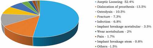
Statistical data shows that loosening of the joints is the prime reason for the revised surgery. The loosening of joints is due to wear in the joints. The life expectancy of the implants can be increased if wear at the articulating surfaces is reduced. Many experimental and numerical studies have been performed to estimate the wear of the joints. Experimental techniques are time-consuming even though they are carried out in vitro, using hip simulators. Results of previously conducted experimental studies have been similar to numerical estimation. Thus numerical estimation is considered promising in order to evaluate and predict the mechanical performance of implants.
2.2. Finite Element Analysis (FEA) for hip implants
Finite Element Analysis (FEA) is a numerical method extensively used to solve a variety of complex physical problems. FEA assumes a complex physical domain as a collection of many simple domains with linear or nonlinear attributes (material, geometry, loads, etc.). The fundamental governing differential equation of the physical system is brought down into a set of algebraic equations solved numerically to obtain the solution for non-linear, complex physical systems. With advantages over experimentation and analytical methods, FEA has the potential and versatility to be applied indisputably in all fields of engineering. These techniques are extensively used for solving multi-physics problems in the field of automobiles, aeronautical, and other structural and fluid dynamic applications.
FEA is used for simulating biomechanical environments, such as coronary artery stenting, mechanical channelization of dental implants, knee implants, and hip implants, etc. due to advancements in computational capabilities (Chethan, ogulcan et al., Citation2020). The material behavior of human hip joints is not fully understood. It behaves distinctly under different loading conditions and gait cycles (Walking, running, stair climbing; Li et al., Citation2013; Li et al., Citation2014). FEA studies for hip implants are quite challenging. Previous studies have successfully demonstrated the static structural studies of these implants along with the femur bone by using both ANSYS R-19 and Abacus (Griza et al., Citation2008; Zhang et al., Citation2013; Elkins et al., Citation2011).
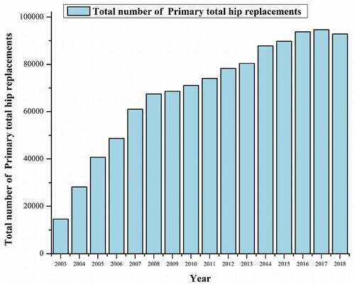
Figure 12. THA procedure year-wise (Brittain et al., Citation2019).
2.3. Need for further research in hip implants
The number of hip replacements by fixation and bearing surface for each year of primary hip replacement for the last 15 years in the United Kingdom as per the National Joint Registry is shown in (Brittain et al., Citation2019),
Total hip replacement is significantly increasing by the day worldwide and is likely to increase by 174% by 2030 (Kurtz et al., Citation2009; Culliford et al., Citation2015). Primary revision is another major concern for total hip replacement with revision rates likely to increase by 137% (Value Dossier, Citation2012).
Aseptic loosening due to wear in the joints resulting from the failure of the bearing surfaces is considered the most common reason for revision hip arthroplasty (Burger et al., Citation2007). Thus, there is a need to develop a hip implant that could last longer (more than 20 years) and help reduce revision surgery. shows the major previous finite element analysis studies performed on hip implants.
Table 2. Shows some of the finite element analysis studies performed on hip implants
3. Design modifications
The stem is the main component that gives stability to an implant after the surgery (Kim & Yoo, Citation2016). Current designs available in the market have a lifespan of 15 to 20 years (Evans et al., Citation2019). There is a need to improve the life expectancy of these implants to more than 20 years to avoid resurfacing of the hip implants.
(M. J. Q. M. J. Q. Peng et al., Citation2017) analysed the effect of the length of the stem. Two stems with a length of 100 mm and 135 mm were studied. They concluded that the length of the stem played a vital role; an increase in the length of the stem decreased the von Mises stress. (Yılmaz et al., Citation2019) developed four hip implant stem models with different directional hollow holes at the proximal end of the femoral prosthesis. They noted that the holes did not affect the stress values. (Kayabasi & Erzincanli, Citation2006) studied the fatigue life of four different stem shapes. The stem geometry varied with straight, notched, and curved shapes. (Monif, Citation2012) conducted a study to analyze the effects of cup contact stress on a femur head. Three different geometries (22 mm, 28 mm, 32 mm) of the head of the femur were modeled using ANSYS R-19. The radial clearance considered between the head and cup of the femur was 0, 0.1 and 0.25 mm was. New BETA type low-rigidity titanium alloy and cobalt-chromium-molybdenum (CoCrMo) and Stainless Steel (SS) were used to fabricate the head of the femur. UHMWPE was used for the acetabular cup material with a thickness of 15 mm. The metal backing shell was made of stainless steel of varying thicknesses (1 mm, 2 mm, and 3 mm) due to its high strength. In the 22 mm non-metal backed femur made of titanium alloy, the von Mises stress decreased by 22% in the UHMWPE cup as compared to the CoCrMo femur. Stress in the UHMWPE cup decreased by 33%, 25%, and 28% when the femoral head of 32 mm diameter was used instead of 22 mm. The thickness of 1 mm metal backing resulted in lower stress at the UHMWPE cup with no significant changes in the stress with an increase in the metal backing thickness. (Yan et al., Citation2011) studied the effect of a porous titanium femoral prosthesis on bone remodeling. Different implant materials, including the presently used cobalt–chrome and solid titanium, potential porous titanium were considered. They found bone loss around the implant was significantly affected by the elastic modulus of that prosthesis. A solid cobalt-chrome implant resulted in a reduction in volume and density of the bone compared to a porous titanium implant. The numerical study showed that with an increase in the porosity both volume and density of bone decreased linearly. The strength of porous titanium decreased with an increase in porosity. (Jiang, Citation2007) analyzed four structural models of artificial joints. The materials used included ultra-high molecular weight polyethylene (UHMWPE), CoCrMo alloy, 316 L stainless steel, and Ti-6Al-4 V alloy. Mechanical characteristics under static and dynamic conditions were investigated using the finite element method (FEM). The strain, stress distribution, and elastic deformation under dynamic as well as static conditions were obtained. Four models were used in their study. In the first model, an artificial acetabulum made of UHMWPE matched the metallic femur head prosthesis. The second model used a metallic cup to cover the UHMWPE artificial acetabulum. A layer of artificial cartilage covering the head of the femur was used as the third design. The fourth model was similar to the third one except that a metallic cup covered the UHMWPE acetabulum. The diameter of the femoral head was considered to be 28 mm and an 8 mm thick UHMWPE artificial acetabulum was used. It was concluded that the cartilage layer could spread the load and reduce deformation and peak stress and thus mechanical properties of the model with an artificial cartilage layer and Ti-6Al-4 V cup were the best out of the four models. (Xin et al., Citation2013) analyzed the biomechanical effects on the hip and knee joint after unilateral total hip arthroplasty using finite element analysis (FEM). Cobalt chrome alloy (CoCrMo) was considered as material for stem and head, UHMWPE for an acetabular cup. They concluded that the distribution of load on the ipsilateral side was more than 15% compared to the contralateral side. The maximum stress increased by 9% on the contralateral femoral head. Due to an increase in stiffness or elastic modulus of the implant there was an increase in the total deformation on the contralateral side. (Senalp et al., Citation2007) investigated the static, dynamic and fatigue behaviour of Ti–6Al–4 V and CoCrMo metal materials. The findings were compared with stem shapes developed by Charnley. Stems with four different surface curvatures straight, notched, notched and curved shapes were designed and considered for the study. They found all the stems safe under stress. Ti-6Al-4 V notched stem was the best among all models under static as well as dynamic conditions. The safety factors for fatigue life differed under static and dynamic conditions.
(Virulsri et al., Citation2015) used a small-sized Thai femoral model made of biocompatible stainless steel 316 L (SS316L) and polymethylmethacrylate (PMMA). Cross-sectional areas, such as a circle, oval rectangle, and oval trapezoid were assigned to each part of the prosthesis. Maximum von Mises stresses of 243 MPa were observed. (Ramos et al., Citation2012) designed the novel stem which performed better than some of the commercially available stems and concluded that stem geometry played a vital role in stress distribution. (Bae et al., Citation2011) modeled the modular stems by varying cross-sections such as circular and rectangular. The developed stems can be used for minimally invasive THR surgery. (Baharuddin et al., Citation2014) designed a patient-specific implant stem using the isthmus canal diameter. They concluded that there was a better total fit with increased proximal distribution of load to prevent stress shielding in the calcar region. They also found lesser displacement and micromotions. (Çelik & Kişioğlu, Citation2019) designed the new hip implant stem, narrowing the region of the prosthesis corresponding to the trabecular region of the proximal femur. von Mises stresses were evaluated for the stem with and without narrowing the trabecular region. It was concluded that the stem with the narrower trabecular region had less von Mises stresses. (Malau et al., Citation2019) modeled a porous hip implant and carried out finite element analysis, and observed no significant change in the von Mises stresses with the porosity of the implant. (Zhang et al., Citation2013) experimentally and computationally investigated the fretting of the stemhead joint in a hip implant. They developed the FE-based methodology for fretting wear fatigue prediction. Considering two head/stem materials Co–28Cr–6Mo/DMLS Ti–6Al–4 V and Co–28Cr–6Mo/forged Ti–6Al–4 V for tribological and profilometry tests. They performed a pin on disk reciprocating sliding test to investigate both tribological and wear performance of the two contact arrangements. They found that the hardness and wear resistance of DMLS Ti-6Al-4 V was superior compared to forged Ti-6Al-4 V. The predicted wear depth for both forged Ti-6Al-4 V and DMLS was less than or equal to 1 µm over 10 years of normal operation. (English et al., Citation2015) proposed a computational technique using energy wear law with a three-dimensional finite element model to predict the fretting wear at the taper junction. They modeled the taper fixation using contact analysis. Head and trunnion tapers were modeled and meshed in Abaqus. The wear prediction was carried out for 5million cycles. They found the variation of relative displacement and contact pressure as well as taper wear over 5millions cycles and concluded that the contact pressure reduces from the initial distribution of 120 MPa during the first 2.6 million cycles. They also found the lowest wear rates of 0.4 and 0.36 mm3/yr in the first two years and a wear rate of 0.66 mm3/yr at 4 years.
4. Wear in hip implants
Wear is the progressive damage that leads to loss of material on the surface of the component which is relative to the adjacent working parts (Williams, Citation2005). Aseptic loosening, secondary to wear debris is the major cause for the revision of total hip replacements (Burger et al., Citation2007; Ulrich et al., Citation2008). The presence of foreign particles in the joint gap increases the wear rate of implants (Hembus et al., Citation2018). Studies are performed both in-vitro and in-vivo to estimate the wear rate in the hip implants helps find the life expectancy of the hip implants.
The wear of hip implants can be measured by three approaches namely clinical investigation, an experimental method using a hip simulator, and numerical analysis. In clinical studies, the implants are retrieved to know the penetration of depth when the patients come for the revision surgery. However, as the wear takes place in three dimensions it is difficult to account for the wear rate accurately. In the experimental method, the wear rate is calculated using the hip simulator. The advantage of a hip simulator is mimicking the actual loading conditions, the same as the human movement. The wear is measured by gravimetric methods. Both these approaches for measuring wear rate is time-consuming and also not economical. Thus, numerical analysis gained significant importance to estimate the wear rate in the implants.
FEA is a numerical technique used for an approximation of solutions for complex engineering problems which is difficult to obtain analytically, or which have no analytical solution. FEA has been used widely in the evaluation of orthopedic devices since the 1970s (Taylor & Prendergast, Citation2015). The development of computational capabilities helped solve complex problems which include analysis of bone, tissue engineering, damage assessment due to trauma, and wear. To date, the Linear wear FEA models simulated dry contact between the articulating surfaces and neglected the lubrication between the contacts (Jay Elliot et al., Citation2014; Rawlinson et al., Citation2007). Archard’s wear law was implemented in most of the numerical models either in its original form (Maxian et al., Citation1996a; Dyrkacz et al., Citation2014; Hung & Wu, Citation2002; Maxian et al., Citation1996b; Kang et al., Citation2006; Kurtz et al., Citation1999; Lundberg et al., Citation2007) or in its modified form (Pakhaliuk et al., Citation2015; Pietrabissa et al., Citation1998; Raimondi et al., Citation2001; Goreham-Voss et al., Citation2010; Liu, Fisher, et al., Citation2013b). A modular hip implant consists of a stem, head of the femur, acetabular, and a backing cup(Kindsfater & Lesko, Citation2018). In total there are three contact pairs: head of the femur to the stem, femoral head to the acetabular cup, an acetabular cup to the backing cup. Wear has been observed in all these contact pairs, but the majority of previous studies focused on the wear between acetabular cup against the femoral head also observed an increase in linear wear with an increase in the femoral head diameter (Liu, Fisher, et al., Citation2013a).
(Maxian et al., Citation1996a) estimated the wear rate of three different sizes of femoral heads and compared the results with clinical studies. The femoral head of 22 mm, 28 mm, and 32 mm were considered for the study. A linear wear rate of 0.110, 0.111, and 0.116 mm per year was obtained and compared with the clinical studies. Clinical studies did show linear wear of 0.13, 0.08, and 0.10 mm/year. (Wu et al., Citation2003) estimated wear of the UHMWPE acetabular cup against ceramic heads of 22 mm, 24 mm, 26 mm, 28 mm, 30 mm, and 32 mm in size. The linear wear rate was found to be 0.111, 0.101, 0.092, 0.085, 0.078, and 0.073 mm per year respectively. However, (Sfantos & Aliabadi, Citation2007) concluded that the wear rate increased with an increase in the size of the head of the femur when the femoral head surface is grooved. (Queiroz et al., Citation2013) estimated the linear wear of the acetabular cup made of UHMWPE over the femoral head using ANSYS R-19. The wear of the cups was calculated using Archard’s wear law. The femoral head diameter of 28 mm was considered for the analysis with a tilt of 30°, 45°, and 60° of the femoral head. Linear wear of 0.19 mm, 0.17 mm, and 0.26 mm was observed per year respectively. (Uddin & Zhang, Citation2013) analyzed the wear prediction of ceramic on ceramic hip prosthesis by FEA. Wear for the walking cycle was predicted and also the three-dimensional physiological gait loading and kinematic motions. Based on the contact stress variation, wear at the bearing surface was calculated. The model was applied to three different types of hard-on-hard prostheses, i.e., metal on metal, ceramic on ceramic, and polycrystalline diamond (PCD) on PCD couples. Only the key bearing components i.e., head of the femur and acetabular cup were considered to reduce the computational complexity. The whole gait cycle was considered as 32 discrete instances in which 1 to 19 was the stance phase and 20 to 32 the swing phase. At the 7th gait instance of stance phase, the maximum hip load of 2336 N appeared 2.5 to 3 times the average human weight. PCD on PCD bearing couple had the lowest wear progression with respect to cumulative linear and volumetric wear compared to the metal on metal and ceramic on ceramic couples. (Pakhaliuk et al., Citation2015) observed linear wear of 0.079 mm per year for a 32 mm ceramic femoral head over the UHMWPE acetabular cup. (Hung & Wu, Citation2002) used the numerical approach to study the wear behavior in artificial hip joints. Estimation of wear rates of acetabular cups made of polythene against metallic or ceramic femoral heads. The wear coefficients were considered from pin-on-disk tests. A femoral head and acetabular cup without the stem were designed. UHMWPE was used for the acetabular cup with an inner diameter of 32 mm, 28 mm, and 22 mm and an outer diameter of 50 mm. In their study, they calculated the wear for 1.5 million cycles of the different material combinations, the polyethylene/ ceramic couples showed better wear performance than the polyethylene/metal couples. (Kang et al., Citation2006) used hip implants made of UHMWPE with an acetabular cup and a ceramic femoral head. Femoral heads of different sizes 22 mm, 26 mm, 28 mm, 32 mm, and 36 mm were considered. The linear wear rate in mm/year was found to be 0.056, 0.050, 0.044, 0.042, 0.040 respectively. (Fialho et al., Citation2007) developed the models to estimate the wear at the hip implants. Femoral head of 22 mm was considered for the study. An average linear wear of 0.09 mm per year was observed for the normal walking cycle. (Matsoukas & Kim, Citation2009) considered a complete hip implant for wear estimation between the head of the femur and the acetabular cup. Ti-6Al-4 V alloy was used for the stem, ceramic for the head of the femur, and UHMWPE for an acetabular cup. Linear wear is estimated for both walking and stair climbing loads. Linear wear rate of 0.025 mm for walking load and 0.034 mm per year for stair Climbing load was observed. (Brown et al., Citation2002) estimated the linear wear for the ceramic head of the femur of length 28 mm articulated against the acetabular cup made of UHMWPE. With an increase in surface hardness, the rate of wear was found to be higher. The linear wear rate was 0.09 to 0.2 mm per year with a varying surface hardness of the femoral head. (Patil et al., Citation2003) modeled a 28 mm ceramic femoral head and acetabular cup made of UHMWPE. The abduction angle of 45° and 55° was considered for the estimation of linear wear. Linear wear of 0.036 for 45° and 0.045 mm per year was observed for the 55° abduction angle. A change in the linear wear rate from 5% to 8% with the change in the anteversion angle was observed. (Teoh et al., Citation2002) used a 32 mm head to know the effect of the coefficient of friction on the wear rate. Linear wear was analyzed between the femoral head and the acetabular cup. The coefficient of friction varied from 0 to 0.3 with an interval of 0.05. They found no significant change in the linear wear rate with a change in the coefficient of friction. (Norman et al., Citation2019) studied the effect of stress at the trunnion junction with an increase in the femoral head size. A standard 12/14 mm taper trunnion was considered for the study. Different loading conditions such as single stance, stair climbing, and stumbling were considered. Stresses at taper junction increased with an increase in the femoral head size, and in stair climbing conditions more compared to other activities.
In addition to the numerical studies, several studies have been carried out to date where hip implants have been used to estimate the wear using hip simulators. (Amaral et al., Citation2014) experimentally evaluated the performance of acetabular cups and the head of the femur made of silicon nitride ceramic coated with nanocrystalline diamond (NCD), grown by a hot filament chemical vapor deposition (HFCVD) method. By gravimetry, the volumetric and linear wear were estimated. A six-station hip joint simulator (H52-6-1000 AMTI) was used for the wear test. No squeaking was observed in these NCD samples. In the first half-million cycle (0.0915 mm3 wear) significant polishing of the femoral head with a diamond-coated surface took place. Due to the fine-scale, abrasive wear mechanism Ra surface roughness decreased by seven times. They also found the volumetric wear of the femoral head in the second half million cycles to be 0.0026 mm3 was less compared to the ceramic-ceramic (CoC) hip joints. (Saverio Saverio Affatato et al., Citation2005) investigated the wear behavior of cross-linked polyethylene (XLPE) and convectional UHMWPE which are clinically available acetabular liners. Pre scratched CoCrMo head of the femur (Ra = 0.12 to 0.14 µm) was used in the hip joint wear simulator. UHMWPE showed 40 times more wear compared to XLPE (109 mg and 4 mg for UHMWPE and XLPE respectively) after 3 million cycles under the same condition. The wear particle of XLPE was smaller compared to UHMWPE and the diameter of the wear particle was found to be 0.26 and 0.71 mm respectively. (S. Affatato et al., Citation2010) experimentally investigated the wear behaviour of new cross-linked polyethylene acetabular cups obtained through the Thermo compression process and compared them with conventional and traditionally available cross-linked polyethylene in the hip joint simulator using the bovine serum as a lubricant for ten million cycles. XLPE-RT exhibited less wear than conventional UHMWPE, but more than XLPE. Thus XLPE showed less wear rate compared to all the conventional UHMWPE and XLPE-RT. (S. Affatato et al., Citation2008) studied the wear rate in the different types of acetabular cups such as the conventional and cross-linked (XLPE). All samples were tested against 28 mm CoCrMo femoral heads in 12 station hip simulator for 5 million cycles. γ-sterilized PE GUR1020, γ-sterilized PE GUR1050, EtO-sterilised PE GUR1020, EtO-sterilised XLPE GUR1020, EtO-sterilised XLPE-RT GUR1050 were considered in the study. The main objective of the study was to know the type of sterilized acetabular cup that exhibits less wear rate. The tests were conducted for 5 million cycles and wear rates measured at each interval of 0.5 million cycles. At the end of the test, both the cross-linked (XLPE) had a lesser wear rate compared to the conventional. XLPE GUR1020 exhibited lesser wear rate compared to XLPE-RT GUR1050 with XLPE GUR1020 having an overall lesser wear rate compared to the other types were considered in the study. (Vesa Saikko & Shen, Citation2010) studied the wear behaviour of a new dual mobility design and compared it with the modular MoP total hip design. The stafit type implant paired with 28 mm diameter femoral head and allofit alpha, another modular metal-backed design paired with a 32 mm diameter femoral head were used. Sulene-PE was used for acetabular cup in both the designs. Twelve station anatomic hip joint simulator was used with an acetabular abduction angle of 45° and 60°. The tests were conducted for 5 million cycles with an interval at each 0.5 million cycles. The wear rate of the modular hip prosthesis with a successful clinical history was the same as the new stafit dual mobility designs. No significant effect on wear was observed with increase in the abduction angle from 45° to 60°. (Fisher et al., Citation2002) experimentally investigated the wear, wear debris, and ion release of fully coated surface engineered MoM bearings of hip prosthesis. An anatomical hip simulator was used and the tests were carried out for 5 million cycles. The femoral head was manufactured from low carbon CoCrMo alloy; inserts were manufactured from high carbon CoCrMo alloy. Five bearing systems were used that included 3 thick [8–12 μm] coatings of CrN, CrCN, TiN, and one thin 2 μm diamond-like carbon (DLC) coating. The results were compared with a clinically available MoM cobalt chrome alloy bearing couple. CrCN coatings were applied by arc evaporative physical vapor deposition and DLC by the plasma-assisted chemical vapor deposition technique. The wear rates of all the fully surface engineered prostheses after 2 million cycles were 23-fold lower for the heads and 6-fold lesser for the inserts than normal MoM prostheses. The coated CrCN on CrCN and CrN on CrN combinations showed a 36-fold reduction in wear rate after 5 million cycles compared to the metal on metal (MoM) prostheses. (Bigsby et al., Citation1997) experimentally investigated the wear rate of 32 mm UHMWPE acetabular cups against the zirconia and stainless ceramic heads in the hip simulator. Bovine serum was used as the lubricant. Wear rates were calculated for the walking cycle has been defined by Paul. The wear rate was found to be 34.26 mm3 per million cycles for the metallic head and 29.50 mm3 per million for the zirconia one. (Calculated through Regression analysis of volume change). (Rahman et al., Citation2013) reviewed in-vivo and in-vitro outcomes and the performance of Alumina, Zirconia, and their functional graded material (FGM) for artificial hip joints. Alumina CoC had excellent hardness but low fracture. Zirconia ceramics had low hardness, but relatively high fracture toughness compared to alumina ceramic. Alumina zirconia FGM had high hardness at the outer surface and good fracture toughness in the inner core compared to the other two. (Goldsmith et al., Citation2000) experimentally evaluated the wear performance of new and existing MoM implants. Four pairs of the existing metal on metal implants of 28 mm diameter and six new pairs of MoM implants of 36 mm diameter in ten stations hip joint simulator with 25% bovine serum were considered. The new heads and cups were made up of high carbon Co Cr Mo alloy (ASTM F1537). Equal wear was observed in the cups and heads of MoM joints. MoM THR of 36 mm diameter had less volumetric wear of 0.36mm3/106 cycles than MoM prosthesis of 28 mm diameter with 0.45 mm3/106 cycles. (Spriano et al., Citation2005) experimentally evaluated the metal ion release over the surface modified with relevant tantalum enhancement. Tantalum was considered due to low toxicity and high corrosion resistance. A pin was used on a disc to know the mechanical behavior of the modified surface. Results revealed that the modified surface had low friction co-efficient in both itself and on alumina and also wear resistance. (V Saikko et al., Citation2001) experimentally analyzed the wear of UHMWPE cups articulated against the femoral head made of CoCr, Alumina, and CoCr coated with diamond-like carbon (DLC) of 28 mm diameter. The new biaxial wear simulator was used for the wear test and bovine serum as the lubricant. Chemical vapor deposition of the DLC coating with a thickness of 3 μm was performed. The tests were carried out for 3million cycles for all three types of heads against UHMWPE cups. The mating surface was changed during visual and microscopic examination. The average wear rates of cups were 48 and 56 mg per 1 million cycles for alumina and CoCr heads and 58 mg per 1 million cycles for DLC coated CoCr heads. In their study, the DLC coating had no significance in reducing the wear rate compared to the head which was not coated. (Roy et al., Citation2010) experimentally evaluated the hardness of CoCr and Mg-PSZ with and without the Diamond-like carbon (DLC) coating by using the Vickers hardness machine. They used the 28 mm diameter never femoral heads made up of CoCr alloy and Mg-PSZ alloy which were never used earlier. The coating was applied by the chemical vapor deposition technique of 3 μm thickness. They found the Vickers microhardness of 4.28 and 10.6 GPa for non-coated CoCr and Mg-PSZ specimens respectively. An increase in hardness with DLC coating for both CoCr and Mg-PSZ specimens was observed. Hv improved by 18–25% (5.07–5.35GPa) for the CoCr specimen and 27–40% (13.4 to 14.8GPa) for the Mg-PSZ specimen. (Firkins et al., Citation2001) experimentally evaluated the wear volume and wear debris generated from the MoM, CoC and Zirconia ceramic-on-UHMWPE hip joints in the same hip joint simulator under identical conditions. They used i.) Zirconia ceramic femoral heads on UHMWPE acetabular cups, ii.) Low carbon chrome wrought cobalt alloy femoral heads on high carbon wrought cobalt chrome alloy acetabular cups and iii.) Alumina ceramic femoral heads on alumina ceramic acetabular cups of 28 mm heads. The wear tests were carried out for 5 million cycles. Gravimetrically, the wear volume is determined for every million cycles. They found an initial higher wear rate, followed by lower steady wear rate. The average wear rate was found to be 31 mm3/million cycles for zirconia ceramic on UHMWPE, 1.23 mm3/million cycles for MoM and 0.05 mm3/million cycles for CoC prosthesis which is significantly lower compared to other two. (Gregson, Citation1994) studied wear generation due to motion between polished and shot blasted Ti-6Al-4 V or Co-Cr surfaces and cortical bone in vitro. Seven solid cylinders of 25 mm length and 16 mm diameter were manufactured by Ti-alloy and Co-Cr alloy. Five cylinders were polished in each type and two were shoot blasted using the coarse alumina grit. Shoot blasting induced residual stress and roughness of the surface. A 25 mm long femoral shaft with an internal diameter of 16 mm was prepared from a previously healthy human cadaver. A load of 466 N and 233 N was used for the polished surface and 466 N for shoot blasted specimens. Under the following loads, the cylinders oscillated through 30° about the long axis at a frequency of 1 Hz. The tests lasted for 25 hours for polished specimens and 4 hours for shot-blasted specimens because of their severe bone wear. All bone samples lost thickness. Ti-alloys shoot blasted alloys had a greater loss. CoCr had very less wear compared to all the other specimens. (Essner et al., Citation2005) experimentally compared the wear performance of alumina ceramic-on cross-linked polyethylene [C-CLPE], metal-on-metal [MoM] and alumina-on-alumina [CoC]. The comparison was done due to its high performance and lower wear as hip replacement bearings. Hip simulators with twelve stations were used for wear testing at 1 Hz under a joint reaction profile. Irrespective of head size CLPE showed a 10-fold reduction in wear rate over the PE. Even though the wear rate of metal is nonlinear and highly variable it showed a wear rate is nine-fold less than the PE. CoC showed less wear rate with a consistent 500-fold wear reduction over PE and 50-fold over both MoM and C-CLPE bearings. (Wang et al., Citation2001) studied the effect of contact stress on wear and friction of UHMWPE acetabular cups. From the single extruded GUR1050 UHMWPE acetabular cups of various internal diameters were machined. The wear tests were carried out in an eight-station hip simulator and friction tests were carried out in a friction simulator. Cobalt-chromium femoral heads with a nominal diameter of 32 mm were used against these cups for wear and friction tests. The tests were carried out for 2 million cycles. The wear and friction were reduced with an increase in maximum contact stress. (Brockett et al., Citation2007) experimentally investigated the friction of different bearing under different loads and lubricant conditions. They used a hip wear simulator and 28 mm diameter bearing for the combination of materials like Ceramic on ceramic (CoC), metal on polyethylene (MoP), Metal on Metal (MoM), and Ceramic on metal (CoM). They applied simple loading and a unidirectional motion to the femoral head. All combinations were performed under swing phase loads of 25 N, 100 N, 300 N for friction measurements. CoC and CoM bearings demonstrated low friction compared to MoM. Increasing the swing load phase increased the friction factor in all the combinations. (Shi et al., Citation2003) studied the tribological performance of different implant materials. They considered four friction pairs in their study namely Al2O3 ball on 440 C stainless steel plate (AB/SSP), 440 C stainless steel ball on 440 C stainless steel plate (SSB/SSP), ZrO2 ball on 440 C stainless steel plate (ZB/SSP), DLC-thin-film-coated 440 C stainless steel ball on 440 C stainless steel plate (DSSB/SSP). For preliminary material evaluation, a pin on flat contact was used. The test was carried out with the bovine serum for lubrication. The wear and frictions tests were done with a normal load of 50 N and a frequency of 1 Hz. The optical profilometer was used to measure the wear volumes on the balls and flat samples. The scanning electron microscope was used to scan the worn surface. DLC coated surface showed half of the friction coefficient which was half of the other three types when sliding against the stainless-steel plate. The wear of the stainless steel, ZrO2, Al2O3, and DLC thin film coated on stainless steel plates was 1.55x10⁶, 3.24x10⁶, 3.79x10⁶, and 3.4 × 106 μm3 respectively. Thus it was concluded that DLC coated stainless steel against stainless steel plate had very less wear compared to the rest.
5. Conclusion
Extensive research has been carried out from the early 1990s to meet the ever-growing challenges in the field of total hip replacement. Currently, many designs of hip implants are available in the market which include both modular and nonmodular types. The modular types of hip implants are used these days due to their superior mechanical performance. Different designs of implants are used to evaluate the mechanical performance with different shapes and sizes. Wear is the predominant factor due to which revision of the hip joint is necessary. Increased wear could lead to aseptic loosening which increased the revision rate of hip prosthesis. Various methods have been used to reduce wear and increase the life of the prosthetic joint by surface modification techniques, cross-linking, and incorporation of new designs into the implant.
Literature mainly focused on different materials used in the hip implants, design, and coatings which influence the wear rate of implants. In-vitro and in-vivo works were reviewed for deeper insight into the prosthesis and hip joint prosthesis. It is clear that the shape of the stem plays a vital role in the performance of implants. With different types of stems and varying surface curvatures, the notched stems exhibited proved to be the best for both static and dynamic conditions. The metal backing cup resulted in lower stress at the UHMWPE cup with no significant changes in the stress with an increase in the metal backing shell beyond 1 mm thickness.
Previous numerical studies performed to estimate the linear wear rate among hip implants focused on the acetabular component articulating against the femoral head. Most studies neglected other contact pairs even though wear was observed in these contacts. There were no standard set of loading conditions taken into consideration to evaluate the hip implant numerically and hip simulation studies. Due to variation of loading conditions, the geometry of implants, size of the femoral head, different materials considered for the analysis, wear rates were found to differ considerably across the FEA models and also with experimental studies. The effect of wear generated in the backing cup against the acetabular cup and trunnion junction of hip implants is still not known clearly. Very few studies have been performed for the optimization of taper design and reducing the wear rate in the taper junction. Currently, a standard taper of 12/14 mm is used in hip implants but no studies have been carried out to know the effect of the mechanical performance of the hip implant if the geometry of this taper trunnion junction is varied.
Consent for publication
All authors consent to the publication of this manuscript.
Acknowledgements
The authors thank the Manipal Institute of Technology, Manipal Academy, Manipal for providing all the support to write this review article.
Disclosure statement
No potential conflict of interest was reported by the author(s).
Additional information
Funding
Notes on contributors

Chethan K N
Dr. Chethan K N working as Assistant Professor-Senior Scale in the Department of Aeronautical and Automobile Engineering, Manipal Institute of Technology, Manipal Academy of Higher Education, Manipal, Karnataka, India. He holds B.E. (Mechanical Engineering), M.Tech (Manufacturing Engineering & Technology) and Ph.D. (Computational Biomechanics) degrees. He has a more than Nine years of teaching and research experience. His area of interest includes Biomechanics of the hip joint, Finite element analysis of biomedical implants, Composite materials, and Manufacturing of medical implants. The author has published several articles in reputed journals related to finite element analysis of hip implants, mechanical characterization of materials, and composite materials.
References
- Affatato, S., Bersaglia, G., Rocchi, M., Taddei, P., Fagnano, C., & Toni, A. (2005). Wear behaviour of cross-linked polyethylene assessed in vitro under severe conditions. Biomaterials, 26(16), 3259–30. https://doi.org/10.1016/j.biomaterials.2004.07.070
- Affatato, S., Zavalloni, M., Spinelli, M., Costa, L., Bracco, P., & Viceconti, M. (2010). Long-term in-vitro wear performance of an innovative thermo-compressed cross-linked polyethylene. Tribology International, 43(1–2), 22–28. https://doi.org/10.1016/j.triboint.2009.04.049
- Affatato, S., Zavalloni, M., Taddei, P., Di Foggia, M., Fagnano, C., & Viceconti, M. (2008). Comparative study on the wear behaviour of different conventional and cross-linked polyethylenes for total hip replacement. Tribology International, 41(8), 813–822. https://doi.org/10.1016/j.triboint.2008.02.006
- Alvarez-Vera, M., Contreras-Hernandez, G. R., Affatato, S., & Hernandez-Rodriguez, M. A. L. (2014). A novel total hip resurfacing design with improved range of motion and edge-load contact stress. Materials and Design, 55(1), 690–698. https://doi.org/10.1016/j.matdes.2013.10.031
- Amaral, M., Maru, M. M., Rodrigues, S. P., Gouvêa, C. P., Trommer, R. M., Oliveira, F. J., Achete, C. A., & Silva, R. F. (2014). Extremely low wear rates in hip joint bearings coated with nanocrystalline diamond. Tribology International, 89(1), 72–77. https://doi.org/10.1016/j.triboint.2014.12.008
- Ashkanfar, A., Langton, D. J., & Joyce, T. J. (2017). A large taper mismatch is one of the key factors behind high wear rates and failure at the taper junction of total hip replacements: A finite element wear analysis. Journal of the Mechanical Behavior of Biomedical Materials, 69(1), 257–266. https://doi.org/10.1016/j.jmbbm.2017.01.018
- Babić, M., Verić, O., Božić, Ž., & Sušić, A. (2020). Finite element modelling and fatigue life assessment of a cemented total hip prosthesis based on 3D scanning. Engineering Failure Analysis, 113(February), 104536. https://doi.org/10.1016/j.engfailanal.2020.104536
- Bae, J. Y., Farooque, U., Lee, K. W., Kim, G. H., Jeon, I., & Yoon, T. R. (2011). Development of hip joint prostheses with modular stems. CAD Computer Aided Design, 43(9), 1173–1180. https://doi.org/10.1016/j.cad.2011.05.004
- Baharuddin, M. Y., Salleh, S. H., Zulkifly, A. H., Lee, M. H., Noor, A. M., Harris, A. R., Majid, N. A., & Abd Kader, A. S. (2014). Design process of cementless femoral stem using a nonlinear three dimensional finite element analysis. BMC Musculoskeletal Disorders, 15(1), 1–17. https://doi.org/10.1186/1471-2474-15-30
- Bashiri, A., Sallam, H. E. M., & Abd-Elhady, A. A. (2020). Progressive failure analysis of a hip joint based on extended finite element method. Engineering Failure Analysis, 117(March), 104829. https://doi.org/10.1016/j.engfailanal.2020.104829
- Bechstedt, M., Gustafson, J. A., Mell, S. P., Gührs, J., Morlock, M. M., Levine, B. R., & Lundberg, H. J. (2020). Contact conditions for total hip head-neck modular taper junctions with microgrooved stem tapers. Journal of Biomechanics, xxxx(103), 109689. https://doi.org/10.1016/j.jbiomech.2020.109689
- Bevill, S. L., Bevill, G. R., Penmetsa, J. R., Petrella, A. J., & Rullkoetter, P. J. (2005). Finite element simulation of early creep and wear in total hip arthroplasty. Journal of Biomechanics, 38(12), 2365–2374. https://doi.org/10.1016/j.jbiomech.2004.10.022
- Bhalekar, R. M., Smith, S. L., & Joyce, T. J. (2019). Wear at the taper-trunnion junction of contemporary ceramic-on-ceramic hips shown in a multistation hip simulator. Journal of Biomedical Materials Research - Part B Applied Biomaterials, 107(4), 1199–1209. https://doi.org/10.1002/jbm.b.34213
- Bigsby, R. J. A., Hardaker, C. S., & Fisher, J. (1997). Wear of ultra-high molecular weight polyethylene acetabular cups in a physiological hip joint simulator in the anatomical position using bovine serum as a lubricant. Proc Inst Mech Eng H, 211(3), 265–269. https://doi.org/10.1243/0954411971534377
- Bitter, T., Khan, I., Marriott, T., Lovelady, E., Verdonschot, N., & Janssen, D. (2018). Finite element wear prediction using adaptive meshing at the modular taper interface of hip implants. Journal of the Mechanical Behavior of Biomedical Materials, 77(May 2017), 616–623. https://doi.org/10.1016/j.jmbbm.2017.10.032
- Brittain, R., Young, E., Mccormack, V., & Swanson, M. (2019). 16th Annual Report 2019:National Joint Registry for England, Wales, Northern Ireland and the Isle Of Man, London. December 2018. https://www.hqip.org.uk/wp-content/uploads/2018/11/NJR-15th-Annual-Report-2018.pdf
- Brockett, C., Williams, S., Jin, Z., Isaac, G., & Fisher, J. (2007). Friction of total hip replacements with different bearings and loading conditions. Journal of Biomedical Materials Research Part B: Applied Biomaterials, 81B(2), 508–515. https://doi.org/10.1002/jbm.b.30691
- Brown, T. D., Stewart, K. J., Nieman, J. C., Pedersen, D. R., & Callaghan, J. J. (2002). Local head roughening as a factor contributing to variability of total hip wear: A finite element analysis. Journal of Biomechanical Engineering, 124(6), 691–698. https://doi.org/10.1115/1.1517275
- Burger, N. D. L., de Vaal, P. L., & Meyer, J. P. (2007). Failure analysis on retrieved ultra high molecular weight polyethylene (UHMWPE) acetabular cups. Engineering Failure Analysis, 14(7), 1329–1345. https://doi.org/10.1016/j.engfailanal.2006.11.005
- Calais-Germain, B. (2004). Anatomy of movement. Chemistry & Biodiverstiy. http://onlinelibrary.wiley.com/doi/10.1002/cbdv.200490137/abstract
- Çelik, T., & Kişioğlu, Y. (2019). Evaluation of new hip prosthesis design with finite element analysis. Australasian Physical and Engineering Sciences in Medicine, 42(4), 1033–1038. https://doi.org/10.1007/s13246-019-00802-0
- Chethan, K. N., Bhat, S. N., Zuber, M., & Shenoy, S. B. (2019). Patient-specific static structural analysis of femur bone of different lengths. The Open Biomedical Engineering Journal, 12(1), 108–114. https://doi.org/10.2174/1874120701812010108
- Chethan, K. N., Ogulcan, G., Bhat, N. S., Zuber, M., & Shenoy, B. S. (2020). Wear estimation of trapezoidal and circular shaped hip implants along with varying taper trunnion radiuses using finite element method. Computer Methods and Programs in Biomedicine, 196(1), 105597. https://doi.org/10.1016/j.cmpb.2020.105597
- Chethan, K. N., Satish Shenoy, B., & Shyamasunder Bhat, N. (2018). Role of different orthopedic biomaterials on wear of hip joint prosthesis: A review. Materials Today: Proceedings, 5(10), 20827–20836. https://doi.org/10.1016/j.matpr.2018.06.468
- Chethan, K. N., Shyamasunder Bhat, N., & Satish Shenoy, B. (2018). Biomechanics of hip joint: A systematic review. International Journal of Engineering and Technology(UAE), 7(3), 1672–1676. https://doi.org/10.14419/ijet.v7i3.15231
- Chethan, K. N., Shyamasunder Bhat, N., Zuber, M., & Satish Shenoy, B. (2019). Finite element analysis of different hip implant designs along with femur under static loading conditions. Journal of Biomedical Physics and Engineering, 9(5), 507–516. https://doi.org/10.31661/jbpe.v0i0.1210
- Chethan, K. N., Shyamasunder Bhat, N., Zuber, M., & Satish Shenoy, B. (2021). Finite element analysis of hip implant with varying in taper neck lengths under static loading conditions. Computer Methods and Programs in Biomedicine, 208(1), 106273. https://doi.org/10.1016/j.cmpb.2021.106273
- Chethan, K. N., Zuber, M., Bhat, S. N., & Shenoy, S. B. (2019). Comparative study of femur bone having different boundary conditions and bone structure using finite element method. The Open Biomedical Engineering Journal, 12(1), 115–134. https://doi.org/10.2174/1874120701812010115
- Chillag, K. J. (2016). Giants of orthopaedic surgery: Austin T. Moore MD. Clinical Orthopaedics and Related Research, 474(12), 2606–2610. https://doi.org/10.1007/s11999-016-5116-5
- Cilingir, A. C. (2010). Finite element analysis of the contact mechanics of ceramic-on-ceramic hip resurfacing prostheses. Journal of Bionic Engineering, 7(3), 244–253. https://doi.org/10.1016/S1672-6529(10)60247-8
- Courpied, J. P., & Caton, J. H. (2011). Total hip arthroplasty, state of the art for the 21st century. International Orthopaedics, 35(2), 149–150. https://doi.org/10.1007/s00264-011-1207-9
- Cross, M. B., Nam, D., & Mayman, D. J. (2012). Ideal femoral head size in total hip arthroplasty balances stability and volumetric wear. HSS Journal®: The Musculoskeletal Journal of Hospital for Special Surgery, 8, 270–274. https://doi.org/10.1007/s11420-012-9287-7
- Culliford, D., Maskell, J., Judge, A., Cooper, C., Prieto-Alhambra, D., & Arden, N. K. (2015). Future projections of total hip and knee arthroplasty in the UK: Results from the UK clinical practice research datalink. Osteoarthritis and Cartilage, 23(4), 594–600. https://doi.org/10.1016/j.joca.2014.12.022
- Damm, P., Bender, A., Duda, G., & Bergmann, G. (2017). In vivo measured joint friction in hip implants during walking after a short rest. PLoS ONE, 12(3), 1–14. https://doi.org/10.1371/journal.pone.0174788
- Darwich, A., Nazha, H., & Abbas, W. (2019). Numerical study of stress shielding evaluation of hip implant stems coated with composite (carbon/PEEK) and polymeric (PEEK) coating materials. Biomedical Research, 30(1), 169–174. https://doi.org/10.35841/biomedicalresearch.30-18-1048
- Dyrkacz, R. M. R., Brandt, J. M., Morrison, J. B., O’ Brien, S. T., Ojo, O. A., Turgeon, T. R., & Wyss, U. P. (2014). Finite element analysis of the head-neck taper interface of modular hip prostheses. Tribology International, 91(1), 206–213. https://doi.org/10.1016/j.triboint.2015.01.016
- Elkins, J. M., Callaghan, J. J., & Brown, T. D. (2014). Stability and trunnion wear potential in large-diameter metal-on-metal total hips: A finite element analysis. Clinical Orthopaedics and Related Research, 472(2), 529–542. https://doi.org/10.1007/s11999-013-3244-8
- Elkins, J. M., O’Brien, M. K., Stroud, N. J., Pedersen, D. R., Callaghan, J. J., & Brown, T. D. (2011). Hard-on-hard total hip impingement causes extreme contact stress concentrations. Clinical Orthopaedics and Related Research, 469(2), 454–463. https://doi.org/10.1007/s11999-010-1632-x
- English, R., Ashkanfar, A., & Rothwell, G. (2015). A computational approach to fretting wear prediction at the head-stem taper junction of total hip replacements. Wear, 338– 339(1), 210–220. https://doi.org/10.1016/j.wear.2015.06.016
- Essner, A., Sutton, K., & Wang, A. (2005). Hip simulator wear comparison of metal-on-metal, ceramic-on-ceramic and crosslinked UHMWPE bearings. Wear, 259(7–12), 992–995. https://doi.org/10.1016/j.wear.2005.02.104
- Evans, J. T., Evans, J. P., Walker, R. W., Blom, A. W., Whitehouse, M. R., & Sayers, A. (2019). How long does a hip replacement last? A systematic review and meta-analysis of case series and national registry reports with more than 15 years of follow-up. The Lancet, 393(10172), 647–654. https://doi.org/10.1016/S0140-6736(18)31665-9
- Fallahnezhad, K., Oskouei, R. H., Badnava, H., & Taylor, M. (2017). An adaptive finite element simulation of fretting wear damage at the head-neck taper junction of total hip replacement: The role of taper angle mismatch. Journal of the Mechanical Behavior of Biomedical Materials, 75(July), 58–67. https://doi.org/10.1016/j.jmbbm.2017.07.003
- Fialho, J. C., Fernandes, P. R., Eça, L., & Folgado, J. (2007). Computational hip joint simulator for wear and heat generation. Journal of Biomechanics, 40(11), 2358–2366. https://doi.org/10.1016/j.jbiomech.2006.12.005
- Firkins, P. J., Tipper, J. L., Saadatzadeh, M. R., Ingham, E., Stone, M. H., Farrar, R., & Fisher, J. (2001). Quantitative analysis of wear and wear debris from metal-on-metal hip prostheses tested in a physiological hip joint simulator. Bio-Medical Materials and Engineering, 11(2), 143–157.
- Fisher, J., Hu, X. Q., Tipper, J. L., Stewart, T. D., Williams, S., Stone, M. H., Davies, C., Hatto, P., Bolton, J., Riley, M., Hardaker, C., Isaac, G. H., Berry, G., & Ingham, E. (2002). An in vitro study of the reduction in wear of metal-on-metal hip prostheses using surface-engineered femoral heads. Proceedings of the Institution of Mechanical Engineers. Part H, Journal of Engineering in Medicine, 216(4), 219–230. https://doi.org/10.1243/09544110260138709
- Goldsmith, A. A., Dowson, D., Isaac, G. H., & Lancaster, J. G. (2000). A comparative joint simulator study of the wear of metal-on-metal and alternative material combinations in hip replacements. Proceedings of the Institution of Mechanical Engineers. Part H, Journal of Engineering in Medicine, 214(1), 39–47. https://doi.org/10.1243/0954411001535228
- Gomez, P. F., & Morcuende, J. A. (2005). A historical and economic perspective on Sir John Charnley, Chas F. Thackray Limited, and the early arthoplasty industry. The Iowa Orthopaedic Journal, 25, 30–37.
- Goreham-Voss, C. M., Hyde, P. J., Hall, R. M., Fisher, J., & Brown, T. D. (2010). Cross-shear implementation in sliding-distance-coupled finite element analysis of wear in metal-on-polyethylene total joint arthroplasty: Intervertebral total disc replacement as an illustrative application. Journal of Biomechanics, 43(9), 1674–1681. https://doi.org/10.1016/j.jbiomech.2010.03.003
- Grandjean, J., Le Goic, G., Favreliere, H., Ledoux, Y., Samper, S., Formosa, F., Devun, L., & Gradel, T. (2012). Multi-scalar analysis of hip implant components using modal decomposition. Measurement Science and Technology, 23(12), 125702. https://doi.org/10.1088/0957-0233/23/12/125702
- Gray, H. (1960). Gray’s Anatomy. The Anatomical Record, 136(4), 505. https://doi.org/10.1002/ar.1091360410
- Gregson, P. J. (1994). Titanium induced or by motion between alloys cobalt-chrome a metal implant resistance reported and cortical. Journal of Biomedical Materials Research, 76(5), 1–7.
- Griza, S., Reis, M., Reboh, Y., Reguly, A., & Strohaecker, T. R. (2008). Failure analysis of uncemented total hip stem due to microstructure and neck stress riser. Engineering Failure Analysis, 15(7), 981–988. https://doi.org/10.1016/j.engfailanal.2007.10.012
- Gross, S., & Abel, E. W. (2001). A finite element analysis of hollow stemmed hip prostheses as a means of reducing stress shielding of the femur. Journal of Biomechanics, 34(8), 995–1003. https://doi.org/10.1016/S0021-9290(01)00072-0
- Hall, R. M., & Unsworth, A. (1997). Friction in hip prostheses. Biomaterials, 18(15), 1017–1026. https://doi.org/10.1016/S0142-9612(97)00034-3
- Hammerberg, E. M., Wan, Z., Dastane, M., & Dorr, L. D. (2010). Wear and range of motion of different femoral head sizes. Journal of Arthroplasty, 25(6), 839–843. https://doi.org/10.1016/j.arth.2009.07.007
- Harris, W. H. (2012). Edge loading has A paradoxical effect on wear in metal-on-polyethylene total hip arthroplasties. Clinical Orthopaedics and Related Research, 470(11), 3077–3082. https://doi.org/10.1007/s11999-012-2330-7
- Hembus, J., Lux, L., Jackszis, M., Bader, R., & Zietz, C. (2018). Wear analysis of cross-linked polyethylene inserts articulating with alumina and ion-treated cobalt-chromium femoral heads under third-body conditions. Wear, 402–403(February), 216–223. https://doi.org/10.1016/j.wear.2018.02.017
- Hu, C. Y., & Yoon, T. R. (2018). Recent updates for biomaterials used in total hip arthroplasty. Biomaterials Research, 22(1), 1–12. https://doi.org/10.1186/s40824-018-0144-8
- Hung, J.-P., & Wu, J.-S.-S. (2002). A COMPARATIVE STUDY ON WEAR BEHAVIOR OF HIP PROSTHESIS BY FINITE ELEMENT SIMULATION. Biomedical Engineering: Applications, Basis and Communications, 14(4), 139–148. https://doi.org/10.4015/S1016237202000218
- Izzo, G. M. (2012a). Total hip replacement: Structures modeling, gait analysis and report. Support for total hip replacement surgery:structures modeling, gait data analysis and report system. European Journal Translational Myology - Basic Applie Myology, 22(1&2), 53. https://doi.org/10.4081/ejtm.2012.1795
- Izzo, G. M. (2012b). Support for total hip replacement surgery: Structures modeling, Gait data analysis and report system. European Journal of Translational Myology, 22(1–2), 69. https://doi.org/10.4081/bam.2012.1-2.69
- Jackson, J. (2011). Father of the modern hip replacement: Professor Sir John Charnley (1911-82). Journal of Medical Biography, 19(4), 151–156. https://doi.org/10.1258/jmb.2011.011021
- Jay Elliot, B., Gundapaneni, D., & Goswami, T. (2014). Finite element analysis of stress and wear characterization in total ankle replacements. Journal of the Mechanical Behavior of Biomedical Materials, 34(1), 134–145. https://doi.org/10.1016/j.jmbbm.2014.01.020
- Jiang, H. (2007). Static and dynamic mechanics analysis on artificial hip joints with different interface designs by the finite element method. Journal of Bionic Engineering, 4(2), 123–131. https://doi.org/10.1016/S1672-6529(07)60024-9
- Jones, O. (2019). The hip joint - articulations - movements. JAAPA: Official Journal of the American Academy of Physician Assistants, 32(8), 1–7. https://doi.org/10.1097/01.JAA.0000574528.47292.6e
- Joumana Medlej. (2014). Human anatomy fundamentals: Flexibility and joint limitations. Envatotuts+, 1–23. https://design.tutsplus.com/articles/human-anatomy-fundamentals-flexibility-and-joint-limitations--vector-25401
- Kang, L., Galvin, A. L., Jin, Z. M., & Fisher, J. (2006). A simple fully integrated contact-coupled wear prediction for ultra-high molecular weight polyethylene hip implants. Proceedings of the Institution of Mechanical Engineers, Part H: Journal of Engineering in Medicine, 220(1), 33–46. https://doi.org/10.1243/095441105X69033
- Katz, Y., Lubovsky, O., & Yosibash, Z. (2018). Patient-specific finite element analysis of femurs with cemented hip implants. Clinical Biomechanics, 58(October), 74–89. https://doi.org/10.1016/j.clinbiomech.2018.06.012
- Kayabasi, O., & Ekici, B. (2007). The effects of static, dynamic and fatigue behavior on three-dimensional shape optimization of hip prosthesis by finite element method. Materials and Design, 28(8), 2269–2277. https://doi.org/10.1016/j.matdes.2006.08.012
- Kayabasi, O., & Erzincanli, F. (2006). Finite element modelling and analysis of a new cemented hip prosthesis. Advances in Engineering Software, 37(7), 477–483. https://doi.org/10.1016/j.advengsoft.2005.09.003
- Kim, J. T., & Yoo, J. J. (2016). Implant design in cementless hip arthroplasty. Hip & Pelvis, 28(2), 65. https://doi.org/10.5371/hp.2016.28.2.65
- Kindsfater, K., & Lesko, J. (2018). Survivorship of a modular acetabular cup system: Medium- to long-term follow-up. Arthroplasty Today, 4(3), 376–382. https://doi.org/10.1016/j.artd.2017.07.001
- Knight, S. R., Aujla, R., & Biswas, S. P. (2011). 100 years of operative history Er Ci Us E on Er Al. Orthopaedic Reviews, 3(6), 2–4. https://doi.org/10.4081/or.2011.16
- Komistek, R. D., Dennis, D. A., Ochoa, J. A., Haas, B. D., & Hammill, C. (2002). In vivo comparison of hip separation after metal-on-metal or metal-on-polyethylene total hip arthroplasty. Journal of Bone and Joint Surgery - Series A, 84(10), 1836–1841. https://doi.org/10.2106/00004623-200210000-00015
- Kurtz, S. M., Lau, E., Ong, K., Zhao, K., Kelly, M., & Bozic, K. J. (2009). Future young patient demand for primary and revision joint replacement: National projections from 2010 to 2030. Clinical Orthopaedics and Related Research, 467(10), 2606–2612. https://doi.org/10.1007/s11999-009-0834-6
- Kurtz, S. M., Ochoa, J. A., Hovey, C. B., & White, C. V. (1999). Simulation of initial frontside and backside wear rates in a modular acetabular component with multiple screw holes. Journal of Biomechanics, 32(9), 967–976. https://doi.org/10.1016/S0021-9290(99)00043-3
- Lavernia, C. J., Iacobelli, D. A., Villa, J. M., Jones, K., Gonzalez, J. L., & Jones, W. K. (2015). Trunnion-head stresses in THA: Are big heads trouble? Journal of Arthroplasty, 30(6), 1085–1088. https://doi.org/10.1016/j.arth.2015.01.021
- Lee, Y. K., Lee, J. C., Ha, Y. C., & Koo, K. H. (2014). Effect of neck length on third-generation ceramic head failure; finite element and retrieval analysis. Journal of Orthopaedic Science, 19(4), 587–597. https://doi.org/10.1007/s00776-014-0573-8
- Levadnyi, I., Gubaua, J. E., Dicati, G. W. O., Awrejcewicz, J., Gu, Y., Pereira, J. T., & Loskutov, A. (2021). Comparative analysis of the biomechanical behavior of collar and collarless stems: Experimental testing and finite element modelling. Journal of Medical and Biological Engineering, 41(6), 844–855. https://doi.org/10.1007/s40846-021-00652-w
- Levangie, P.K. (2005). Joint structure and function. Arthritis Rheum, 262–264. https://doi.org/10.1002/art.1780240233
- Li, J., Hua, X., Jin, Z., Fisher, J., & Wilcox, R. K. (2014). Biphasic investigation of contact mechanics in natural human hips during activities. Proceedings of the Institution of Mechanical Engineers, Part H: Journal of Engineering in Medicine, 228(6), 556–563. https://doi.org/10.1177/0954411914537617
- Li, J., Stewart, T. D., Jin, Z., Wilcox, R. K., & Fisher, J. (2013). The influence of size, clearance, cartilage properties, thickness and hemiarthroplasty on the contact mechanics of the hip joint with biphasic layers. Journal of Biomechanics, 46(10), 1641–1647. https://doi.org/10.1016/j.jbiomech.2013.04.009
- Lin, Y. T., Wu, J. S. S., & Chen, J. H. (2016). The study of wear behaviors on abducted hip joint prostheses by an alternate finite element approach. Computer Methods and Programs in Biomedicine, 131(1), 143–155. https://doi.org/10.1016/j.cmpb.2016.04.015
- Liu, F., Fisher, J., & Jin, Z. (2013a). Wear prediction of orthopaedic implants. Wear of Orthopaedic Implants and Artificial Joints, 403–418. https://doi.org/10.1533/9780857096128.1.403
- Liu, F., Fisher, J., & Jin, Z. (2013b). Effect of motion inputs on the wear prediction of artificial hip joints. Tribology International, 63(July), 105–114. https://doi.org/10.1016/j.triboint.2012.05.029
- Liu, F., Leslie, I., Williams, S., Fisher, J., & Jin, Z. (2008). Development of computational wear simulation of metal-on-metal hip resurfacing replacements. Journal of Biomechanics, 41(3), 686–694. https://doi.org/10.1016/j.jbiomech.2007.09.020
- Lombardi, A. V., Mallory, T. H., Dennis, D. A., Komistek, R. D., Fada, R. A., & Northcut, E. J. (2000). An in vivo determination of total hip arthroplasty pistoning during activity. Journal of Arthroplasty, 15(6), 702–709. https://doi.org/10.1054/arth.2000.6637
- Lundberg, H. J., Stewart, K. J., Pedersen, D. R., Callaghan, J. J., & Brown, T. D. (2007). Nonidentical and outlier duty cycles as factors accelerating UHMWPE wear in THA: A finite element exploration. Journal of Orthopaedic Research, 25(1), 30–43. https://doi.org/10.1002/jor.20265
- Malau, D. P., Utomo, M. S., Annur, D., Asmaria, T., Prabowo, Y., Rahyussalim, A. J., Supriadi, S., & Amal, M. I. (2019). Finite element analysis of porous stemmed hip prosthesis for children. AIP Conference Proceedings, 2193(December), 1–5. https://doi.org/10.1063/1.5139393
- Matsoukas, G., & Kim, I. Y. (2009). Design optimization of a total hip prosthesis for wear reduction. Journal of Biomechanical Engineering, 131(5), 1–12. https://doi.org/10.1115/1.3049862
- Mattei, L., Di Puccio, F., Piccigallo, B., & Ciulli, E. (2011). Lubrication and wear modelling of artificial hip joints: A review. Tribology International, 44(5), 532–549. https://doi.org/10.1016/j.triboint.2010.06.010
- Maxian, T. A., Brown, T. D., Pedersen, D. R., & Callaghan, J. J. (1996a). A sliding distance coupled finite element formulation for polyethylene wear in total hip arthroplasty. Journal of Biomechanics, 29(5), 687–692. https://doi.org/10.1016/0021-9290(95)00125-5
- Maxian, T. A., Brown, T. D., Pedersen, D. R., & Callaghan, J. J. (1996b). Adaptiive finite element modeling of long-term polyethylene wear in total hip arthroplasty. Journal of Orthopaedic Research, 14(4), 668–675. https://doi.org/10.1002/jor.1100140424
- Mellon, S. J., Liddle, A. D., & Pandit, H. (2013). Hip replacement: Landmark surgery in modern medical history. Maturitas, 75(3), 221–226. https://doi.org/10.1016/j.maturitas.2013.04.011
- Monif, M. M. (2012). Finite element study on the predicted equivalent stresses in the artificial hip joint. Journal of Biomedical Science and Engineering, 05(2), 43–51. https://doi.org/10.4236/jbise.2012.52007
- Nakabayashi, Y., Wevers, H. W., Cooke, T. D. V., & Griffin, M. (1994). Bone strength and histomorphometry of the distal femur. The Journal of Arthroplasty, 9(3), 307–315. https://doi.org/10.1016/0883-5403(94)90086-8
- Nam, D., Osbahr, D. C., Choi, D., Ranawat, A. S., Kelly, B. T., & Coleman, S. H. (2011). Defining the origins of the iliofemoral, ischiofemoral, and pubofemoral ligaments of the hip capsuloligamentous complex utilizing computer navigation. HSS Journal, 7(3), 239–243. https://doi.org/10.1007/s11420-011-9214-3
- Navarro-Zarza, J. E., Villaseñor-Ovies, P., Vargas, A., Canoso, J. J., Chiapas-Gasca, K., Hernández-Díaz, C., Saavedra, M. Á., & Kalish, R. A. (2012). Clinical anatomy of the pelvis and hip. Reumatologia Clinica, 8(SUPPL.2), 33–38. https://doi.org/10.1016/j.reuma.2012.10.006
- Norman, T. L., Denen, J. E., Land, A. J., Kienitz, D. M., & Fehring, T. A. (2019). Taper-trunnion interface stress varies significantly with head size and activity. Journal of Arthroplasty, 34(1), 157–162. https://doi.org/10.1016/j.arth.2018.09.004
- Pakhaliuk, V., Polyakov, A., Kalinin, M., & Kramar, V. (2015). Improving the finite element simulation of wear of total hip prosthesis’ spherical joint with the polymeric component. Procedia Engineering, 100(January), 539–548. https://doi.org/10.1016/j.proeng.2015.01.401
- Pal Singh, A. (2015). Hip joint anatomy. Bone and Spine. http://boneandspine.com/hip-joint-anatomy/
- Patil, S., Bergula, A., Chen, P. C., Colwell, C. W., & D’lima, D. D. (2003). Polyethylene wear and acetabular component orientation. Journal of Bone and Joint Surgery - Series A, 85(SUPPL. 4), 56–63. https://doi.org/10.2106/00004623-200300004-00007
- Peng, M. J. Q., Chen, H. Y., Hu, Y., Ju, X., & Bai, B. (2017). Finite element analysis of porously punched prosthetic short stem virtually designed for simulative uncemented hip arthroplasty. BMC Musculoskeletal Disorders, 18(1), 1–12. https://doi.org/10.1186/s12891-017-1651-9
- Peng, Y., Arauz, P., An, S., & Kwon, Y. M. (2019). Computational modeling of polyethylene wear in total hip arthroplasty using patient-specific kinematics-coupled finite element analysis. Tribology International, 129(August 2018), 162–166. https://doi.org/10.1016/j.triboint.2018.08.009
- Pietrabissa, R., Raimondi, M., & Di Martino, E. (1998). Wear of polyethylene cups in total hip arthroplasty: A parametric mathematical model. Medical Engineering and Physics, 20(3), 199–210. https://doi.org/10.1016/S1350-4533(98)00004-6
- Portigliatti-Barbos, M., Carando, S., Ascenzi, A., & Boyde, A. (1987). On the structural symmetry of human femurs. Bone, 8(3), 165–169. https://doi.org/10.1016/8756-3282(87)90016-0
- Putz, R., & Pabst, R. (2006). Sobotta Atlas of human anatomy. volume 2, trunk, viscera, lower limb (Vol. 2). Elsevier Inc. http://www.naprapat.com/sobotta/sobotta2.pdf
- Queiroz, R. D., Oliveira, A. L. L., Trigo, F. C., & Lopes, J. A. (2013). A finite element method approach to compare the wear of acetabular cups in polyethylene according to their lateral tilt in relation to the coronal plane. Wear, 298–299(1), 8–13. https://doi.org/10.1016/j.wear.2012.12.032
- Rahman, H. S. A., Choudhury, D., Osman, N. A. A., Shasmin, H. N., & Abas, W. A. B. W. (2013). In vivo and in vitro outcomes of alumina, zirconia and their composited ceramic-on-ceramic hip joints. Journal of the Ceramic Society of Japan, 121(1412), 382–387. https://doi.org/10.2109/jcersj2.121.382
- Raimondi, M. T., Santambrogio, C., Pietrabissa, R., Raffelini, F., & Molfetta, L. (2001). Improved mathematical model of the wear of the cup articular surface in hip joint prostheses and comparison with retrieved components. Proceedings of the Institution of Mechanical Engineers, Part H: Journal of Engineering in Medicine, 215(4), 377–390. https://doi.org/10.1243/0954411011535966
- Ramos, A., Completo, A., Relvas, C., & Simões, J. A. (2012). Design process of a novel cemented hip femoral stem concept. Materials and Design, 33(1), 313–321. https://doi.org/10.1016/j.matdes.2011.07.039
- Rawlinson, J. J., Punga, K. P., Gunsallus, K. L., Bartel, D. L., & Wright, T. M. (2007). Wear simulation of the ProDisc-L disc replacement using adaptive finite element analysis. Journal of Neurosurgery: Spine, 7(2), 165–173. https://doi.org/10.3171/SPI-07/08/166
- Roach, K. E., & Miles, T. P. (1991). Normal hip and knee active range of motion: The relationship to age. Physical Therapy, 71(9), 656–665. https://doi.org/10.1093/ptj/71.9.656
- Roy, M. E., Whiteside, L. A., Xu, J., & Katerberg, B. J. (2010). Diamond-like carbon coatings enhance the hardness and resilience of bearing surfaces for use in joint arthroplasty. Acta Biomaterialia, 6(4), 1619–1624. https://doi.org/10.1016/j.actbio.2009.10.037
- Rymek, J., & Ciszkiewicz, A. (2022). Analyzing the sensitivity of a procedure for obtaining a spherical contact pair to model the hip joint. In: Pijanowska D.G., Zieliński K., Liebert A., Kacprzyk J. (eds) Biocybernetics and Biomedical Engineering – Current Trends and Challenges. Lecture Notes in Networks and Systems, vol 293. Springer, Cham. https://doi.org/10.1007/978-3-030-83704-4_11
- Saikko, V., Ahlroos, T., Calonius, O., Keränen, & Keränen, J. (2001). Wear simulation of total hip prostheses with polyethylene against\nCoCr, alumina and diamond-like carbon. Biomaterials, 22(12), 1507–1514. https://doi.org/10.1016/S0142-9612(00)00306-9
- Saikko, V., & Shen, M. (2010). Wear comparison between a dual mobility total hip prosthesis and a typical modular design using a hip joint simulator. Wear, 268(2–3), 617–621. https://doi.org/10.1016/j.wear.2009.10.011
- Sankar, W. N., Laird, C. T., & Baldwin, K. D. (2012). Hip range of motion in children: What is the norm? Journal of Pediatric Orthopaedics, 32(4), 399–405. https://doi.org/10.1097/BPO.0b013e3182519683
- Saxena, A. K., Misra, R. K., & Dixit, A. (2015). Numerical Analysis of Hip Joint Implant. Materials Today: Proceedings, 2(4–5), 1649–1656. https://doi.org/10.1016/j.matpr.2015.07.092
- Scifert, C. F., Brown, T. D., & Lipman, J. D. (1999). Finite element analysis of a novel design approach to resisting total hip dislocation. Clinical Biomechanics, 14(10), 697–703. https://doi.org/10.1016/S0268-0033(99)00054-6
- Senalp, A. Z., Kayabasi, O., & Kurtaran, H. (2007). Static, dynamic and fatigue behavior of newly designed stem shapes for hip prosthesis using finite element analysis. Materials and Design, 28(5), 1577–1583. https://doi.org/10.1016/j.matdes.2006.02.015
- Sfantos, G. K., & Aliabadi, M. H. (2007). Total hip arthroplasty wear simulation using the boundary element method. Journal of Biomechanics, 40(2), 378–389. https://doi.org/10.1016/j.jbiomech.2005.12.015
- Shaik, S. A., Bose, K., & Cherukuri, H. P. (2012). A study of durability of hip implants. Materials and Design, 42(1), 230–237. https://doi.org/10.1016/j.matdes.2012.05.049
- Shi, B., Ajayi, O. O., Fenske, G., Erdemir, A., & Liang, H. (2003). Tribological performance of some alternative bearing materials for artificial joints. Wear, 255(7–12), 1015–1021. https://doi.org/10.1016/S0043-1648(03)00276-X
- Spina, A. A. (2007). External coxa saltans (snapping hip) treated with active release techniques: A case report. The Journal of the Canadian Chiropractic Association, 51(1), 23–29. http://www.ncbi.nlm.nih.gov/pubmed/17657288%0Ahttp://www.pubmedcentral.nih.gov/articlerender.fcgi?artid=PMC1924651
- Spriano, S., Vernè, E., Faga, M. G., Bugliosi, S., & Maina, G. (2005). Surface treatment on an implant cobalt alloy for high biocompatibility and wear resistance. Wear, 259(7–12), 919–925. https://doi.org/10.1016/j.wear.2005.02.011
- Tai, C. L., Shih, C. H., Chen, W. P., Lee, S. S., Liu, Y. L., Hsieh, P. H., & Chen, W. J. (2003). Finite element analysis of the cervico-trochanteric stemless femoral prosthesis. Clinical Biomechanics, 18(6), 53–58. https://doi.org/10.1016/S0268-0033(03)00085-8
- Tan, S. C., Teeter, M. G., Del Balso, C., Howard, J. L., & Lanting, B. A. (2015). Effect of taper design on trunnionosis in metal on polyethylene total hip arthroplasty. Journal of Arthroplasty, 30(7), 1269–1272. https://doi.org/10.1016/j.arth.2015.02.031
- Taylor, M., & Prendergast, P. J. (2015). Four decades of finite element analysis of orthopaedic devices: Where are we now and what are the opportunities? Journal of Biomechanics, 48(5), 767–778. https://doi.org/10.1016/j.jbiomech.2014.12.019
- Teoh, S. H., Chan, W. H., & Thampuran, R. (2002). An elasto-plastic finite element model for polyethylene wear in total hip arthroplasty. Journal of Biomechanics, 35(3), 323–330. https://doi.org/10.1016/S0021-9290(01)00215-9
- Uddin, M. S., & Zhang, L. C. (2013). Predicting the wear of hard-on-hard hip joint prostheses. Wear, 301(1–2), 192–200. https://doi.org/10.1016/j.wear.2013.01.009
- Ulrich, S. D., Seyler, T. M., Bennett, D., Delanois, R. E., Saleh, K. J., Thongtrangan, I., Kuskowski, M., Cheng, E. Y., Sharkey, P. F., Parvizi, J., Stiehl, J. B., & Mont, M. A. (2008). Total hip arthroplasties: What are the reasons for revision? International Orthopaedics, 32(5), 597–604. https://doi.org/10.1007/s00264-007-0364-3
- Value Dossier. (2012). Zimmer computer-assisted surgery in total knee arthroplasty value dossier. http://www.zimmer.com/content/dam/zimmer-web/documents/en-US/pdf/medical-professionals/reimbursement/our-science/cas_valuedossier.pdf
- Virulsri, C., Tangpornprasert, P., & Romtrairat, P. (2015). Femoral hip prosthesis design for Thais using multi-objective shape optimization. Materials and Design, 68(1), 1–7. https://doi.org/10.1016/j.matdes.2014.11.027
- Wang, A., Essner, A., & Klein, R. (2001). Proceedings of the Institution of Mechanical Engineers, Part H: Journal of Engineering in Medicine EVect of contact stress on friction and wear of ultra-high molecular weight polyethylene in total hip. Proceedings of the Institution of Mechanical Engineers. Part H, Journal of Engineering in Medicine, 215(2), 133–139. https://doi.org/10.1243/0954411011533698
- Watanabe, Y., Shiba, N., Matsuo, S., Higuchi, F., Tagawa, Y., & Inoue, A. (2000). Biomechanical study of the resurfacing hip arthroplasty: Finite element analysis of the femoral component. Journal of Arthroplasty, 15(4), 505–511. https://doi.org/10.1054/arth.2000.1359
- Williams, J. (2005). Engineering tribology. Engineering Tribology, 9780521609(1), 1–488. https://doi.org/10.1017/CBO9780511805905
- Wroblewski, B. M., Fleming, P. A., & Siney, P. D. (1999). Charnley low-frictional torque arthroplasty of the hip. The Journal of Bone and Joint Surgery. British Volume, 81-B(3), 427–430. https://doi.org/10.1302/0301-620X.81B3.0810427
- Wu, J. S. S., Hung, J. P., Shu, C. S., & Chen, J. H. (2003). The computer simulation of wear behavior appearing in total hip prosthesis. Computer Methods and Programs in Biomedicine, 70(1), 81–91. https://doi.org/10.1016/S0169-2607(01)00199-7
- Xin, Y., Kim, K., & Yang, S. (2013). Analysis of stress and load distribution on hip and knee joint after unilateral total hip arthroplasty. Proceedings, The 2nd International Conference on Information Science and Technology. 23(4), 235–239. https://www.semanticscholar.org/paper/Analysis-of-Stress-and-load-Distribution-on-Hip-and-Xin-Kim/e74f5ea036c47340c7383a71677d5523269aa159
- Yan, W., Berthe, J., & Wen, C. (2011). Numerical investigation of the effect of porous titanium femoral prosthesis on bone remodeling. Materials and Design, 32(4), 1776–1782. https://doi.org/10.1016/j.matdes.2010.12.042
- Yılmaz, S., Calikoglu, E. O., & Kosan, Z. (2019). For an uncommon neurosurgical emergency in a developing country. Nigerian Journal of Clinical Practice, 22(8), 1070–1077. https://doi.org/10.4103/njcp.njcp
- Zhang, T., Harrison, N. M., McDonnell, P. F., McHugh, P. E., & Leen, S. B. (2013). A finite element methodology for wear-fatigue analysis for modular hip implants. Tribology International, 65(1), 113–127. https://doi.org/10.1016/j.triboint.2013.02.016