
 ?Mathematical formulae have been encoded as MathML and are displayed in this HTML version using MathJax in order to improve their display. Uncheck the box to turn MathJax off. This feature requires Javascript. Click on a formula to zoom.
Abstract
Enhancement of heat transfer for turbulent flow in a circular tube heat exchanger using triangular wing vortex generators (TWVG) is presented using Computational Fluid Dynamics methodology. A detailed parametric analysis is carried out to evaluate the impact of non-dimensional base width (0.059–0.216), non-dimensional height (0.039–0.314) and different flow attack angle of TWVG (α = 22.5°, 45°, 67.5°, 90°, 112.5° and 135°) for Re = 6000–18,000. The results show that the TWVG provides considerable heat transfer improvement through two mechanisms such as flow impingement effect on the upstream side and vortex formation on the downstream side. The heat transfer is found to decrease with increasing flow attack angle. However, the friction factor is found to increase from α = 22.5° to α = 90° and drops for all α > 90° due to increased streamlined orientation of vortex generator to the air stream. Longitudinal vortices are formed for α = 22.5°, whereas transverse vortices are generated for all other flow attack angles used in the analysis which are found to have lower flow mixing effect as well as lower coverage of tube wall region. Greater height and base width of TWVG provides greater heat transfer and friction factor enhancement. The maximum enhancement in Nusselt number and friction factor is in the range of 2.61–2.96 and 6.54–8.1 respectively for b/D = 0.216 and h/D = 0.314. The maximum thermal enhancement factor is produced by the configuration having h/D = 0.235 and b/D = 0.059 and has a range of 1.34–1.63.
PUBLIC INTEREST STATEMENT
Owing to ever growing demand for energy due to increased urbanization, the rate at which the fossil fuels are being used for energy generation are at an alarmingly higher rate, which could lead to its faster depletion. Hence, it is compelling to ensure energy conservation wherever possible to save energy. Many engineering applications makes use of heat exchange devices which generally require enhancements for improved performance. This work makes use of specially designed inserts to increase the energy exchange capability of heat exchanger which leads to energy conservation.
1. Introduction
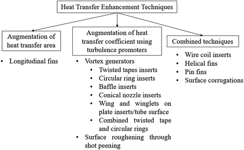
Energy conservation is among the critical objectives of every nation’s energy policy to ensure future energy security amid the rapidly growing energy demand and the depleting energy sources. Much of the energy wastage occurs in the heat exchangers of HVAC systems, power-generation systems, refrigeration system and so on if the heat exchange process is not efficient. Moreover, efficient heat transfer also enables to make the heat exchanging systems more compact which allows for reduced space requirement as well as reduced material cost. In this regard, various efforts in this field are being made where researchers have come up with various types of inserts and attachments that are inserted or built into the heat exchanger tube so as to improve the overall thermal performance of heat exchanger. Heat transfer augmentation can be achieved through active and passive techniques. Devices that operate using passive technique do not need external power supply for their operation. On the contrary, active techniques consume external power supply to provide enhanced heat transfer performance and generally makes use of vibration of flow fluid pipelines as well as scrapers to generate fluid mixing. depicts the various passive techniques used for heat transfer augmentation in tubular heat exchangers.
Figure 1. Different passive heat transfer enhancement techniques used in circular tube heat exchanger.
Vortex generators (VG) are used to enhance heat transfer in tubular heat exchangers which augment the flow turbulence in addition to providing higher temperature gradient at the tube wall due to thermal boundary layer thinning. A parametric investigation of thermal and flow behaviour using delta winglet VG pairs in a circular tube was carried out by (Zhai et al., Citation2019) for six pitch ratio (2.4, 3.6, 4.8, 6.4, 9.6 and 19.2). They report that the pitch ratio has substantial impact on heat transfer enhancement and the maximum TEF (Thermal Enhancement Factor) was obtained for the pitch ratio of 9.6 which corresponds to two winglet rows. Zhang et al. (Citation2020) numerically investigated rectangular winglet VG (RWVG) with two configurations, the parallel and V-shaped arrangement. Numerical results demonstrate that parallel rectangular winglets generate single longitudinal vortex, whereas V-shaped-type rectangular winglet turbulators induce multiple longitudinal vortices. Overall, parallel rectangular winglets with a length ratio of 0.2 and an angle of attack of 75° and V-shaped rectangular winglets vortex generators with a length ratio of 0.2 and an angle of attack of 45° have a better TEF than other investigated cases at the same pressure drop. Xu et al. (Citation2018) made use of four delta winglets on a thin rod inside the tube different angle of attack ranging from 0° to 45°, non-dimensional blockage ratio of 0.1–0.3 and non-dimensional pitch of 1.6–4.8. The greatest reported increase in thermal performance was about 1.45. Xu et al., (Citation2017) numerically studied the effect of winglet vortex generator in a circular tube for varied attack angles and blockage ratios for the Reynolds number range of 6000–33,000. The results show that the best set of parameters for optimum thermal performance is an angle of attack of 30° and a blockage ratio of 0.1. Repeated ring-type ribs (Huang et al., Citation2015) which are basically transverse corrugations are also tested for turbulence enhancement in the airflow, which provide transverse vortices and have limited heat transfer enhancement capability.
Ring inserts such as conical rings were used by (Ibrahim et al., Citation2019) in the form of convergent conical rings, convergent-divergent conical rings, and divergent conical rings for different diameter ratio (0.3–0.7) and non-dimensional pitch (2–4) and reported an optimum TEF of 1.29 for diameter ratio of 0.4 and lower non-dimensional. Nakhchi & Esfahani, (Citation2019) numerically analysed the impact of perforated conical rings with varied number of holes (0–10) for different diameter ratio of ring (0.4, 0.5, and 0.6) and hole diameter ratio (0.06–0.14). Perforated conical rings provide increased flow disturbance and the highest TEF of 1.241 was obtained with 10 holes, ring diameter ratio of 0.6 and hole diameter ratio of 0.1. An experimental study by (Kongkaitpaiboon, Nanan, Eiamsa-ard et al., Citation2010a) shows that the perforated conical rings exhibit a maximum TEF of about 0.92. The heat transmission and friction properties of V-nozzle turbulators placed in a circular tube were examined experimentally by (Eiamsa-ard & Promvonge, Citation2006). A pitch ratio of 2.0, 4.0, and 7.0, which result in three distinct V-nozzle layouts were introduced. The heat transfer rate increased by 2.7 times while a maximum gain of 1.19 was achieved in terms of enhancement efficiency. Wang et al. (Citation2019) examined the impact of spacing length, central angle and slice height of the longitudinally placed vortex generator and found that the concave surface led to the generation of multiple pairs of longitudinal vortices. Nusselt number and friction factor was found to increase by 2.55–7.10 and 2.21–11.27 times respectively.
Some studies made use of central rod inserts to place the VG in the tube and the VG is designed to create swirl flows in the entire flow domain or in the region close to the tube. Twisted cross baffles (Nanan et al., Citation2017) provide a high thermal enhancement factor of 1.7 for the shortest pitch ratio while the propeller-type swirl generator (Bali & Sarac, Citation2014) augment heat transfer to the extent of 190% for two-propeller case with 15° joint angle. Perforated turbulator (Chamoli et al., Citation2017) provides very good TEF enhancement of 1.65 for the perforation index of 16% and smaller relative pitch length of 2. Use of louvered strip inserts (Yaningsih et al., Citation2018) provide a modest TEF of 1.12 for the largest slant angle whose performance is further enhanced to 1.84 by using double perforations (Nakhchi et al., Citation2020) due to amplification of flow turbulent kinetic energy in the vicinity of holes. Further, backward arrangement of louvered strip arrangement (Eiamsa-ard et al., Citation2008) with inclination angle of 15°, 25° and 30° provide 9–24% higher TEF than the forward configuration. Use of twisted conical strips (Pourramezan & Ajam, Citation2016) and bidirectional conical strips (Liu et al., Citation2018) have been shown to perform considerably in the laminar flow regime.
Coiled wire inserts have also been tested to introduce increased flow mixing and heat transfer area. Keklikcioglu & Ozceyhan (Citation2018) experimentally investigated the thermo-hydraulic performance of coiled wire placed in a circular. The wire inserts were coiled in such a way that one of the vertices of triangle faced the entering airflow and they had equilateral triangular cross-section. Installing the coiled wires with a millimetre spacing from the inner wall of tube was used to evaluate the heat transfer increase due to the viscous sublayer disturbance. Six different coiled wire configurations were used in the experiment with three different pitch-to-diameter ratio of 1, 2 and 3 and two different triangle side length-to-tube-diameter ratio of 0.0714 and 0.0892. The highest enhancement factor was obtained as 1.67 for the pitch-to-diameter ratio of 1.0 and triangle side length-to-tube-diameter ratio of 0.0892. Twined coil inserts (Dang & Wang, Citation2021) further enhance the heat transfer process by significantly augmenting the flow vorticity causing intense flow mixing between the core flow and wall region air streams. As a result, the heat transfer is found to increase significantly and exhibit a maximum TEF of 2.16 at Re = 1000.
Twisted tape inserts have been used to increase overall heat transfer enhancement performance with the goal of promoting fluid mixing and heat transfer rate. Rectangular cut twisted tape inserts (Hakim et al., Citation2021), clockwise and counter-clockwise twisted tape inserts (Man et al., Citation2017), perforated twisted tape inserts (Bhuiya et al., Citation2013), twisted tapes using array of wings (Yaningsih & Wijayanta, Citation2017) and perforated twisted (PT) tape inserts with varying axial pitch (Yaningsih et al., Citation2016) have been investigated with varying performance. Use of wing vortex generators on twisted tapes have been shown to perform better among these designs with a TEF of 1.44 in turbulent flow regime. A newly designed twisted tape having parallelogram winglet vortex generator (Lin et al., Citation2017) on it in a tube reveals that the secondary flows emanate from the twisted base tape along with an additional secondary flow from the vortex generator. The thermal performance factor is found to be in the range of 1.25–1.85.
Non-twisted plate inserts with vortex generators attached on it have also been tested. Double-sided delta wing tape inserts (Wijayanta et al., Citation2018) have been shown to provide about 177 % greater heat transfer than plain tube. Triangular winglets (Pourhedayat et al., Citation2020) in forward and backward arrangement on both sides of the plate insert shows improved performance for smaller aspect ratio and longitudinal pitch. Delta-winglet turbulators (Lei et al., Citation2017) that are punched out from the plate insert provide 60.2–117.2% rise in heat transfer with 251–466% rise in pressure drop. Discrete-V-winglet tape (Promvonge et al., Citation2020) has been shown to provide greater thermal enhancement factor than the traditional V-winglet. Winglet vortex generators (Chokphoemphun et al., Citation2015) on plate inserts with a 30° attack angle which were tested for different blockage ratios provide TEF in the range of 1.35–1.59, which is substantially superior to that of wire coil and twisted tape inserts. Perforated delta-winglets (Skullong et al., Citation2017) further enhance the TEF to 1.902 for a blockage ratio of 0.15 and pitch ratio of 1.0. Sompol et al. (Skullong et al., Citation2018) used curved winglets that are mounted periodically on both sides of tape to form two pairs of counter-rotating vortices longitudinally assisting chaotic flow mixing. They evaluated the effect of non-dimensional winglet height, winglet pitch for a given attack angle of 45°. As a further improvement, the winglets are punched provide perforations at a relative winglet height of 0.1 to reduce pressure loss. Five distinct hole diameters (ranging 1.0–3.0 mm) were used on the perforated-curved-winglet tape. The thermal enhancement factor of all perforated-curved-winglet tapes is found to be higher than that of the plain curved-winglet tape with a greatest thermal enhancement factor of 1.76. Sompol et al. (Skullong et al., Citation2016) experimentally investigated the staggered configuration of winglet tapes with perforation using five distinct winglet blockage ratios (0.1–0.3) as well as three distinct winglet non-dimensional pitch (0.5–1.5). At Reynolds number 4180, the staggered-winglet perforated tapes with a blockage ratio of 0.15 and pitch ratio of 1.0 exhibit the maximum thermal enhancement factor of 1.71. Interestingly, in comparison to the staggered-winglet typical non-perforated tape (WTT), the greatest thermal enhancement factor of the staggered-winglet perforated tapes is about 20% higher.
Thus, it is seen that a wide variety of vortex generators are adopted using central rod inserts, plate inserts, twisted tape inserts and coiled wire inserts each having varied levels of heat transfer and pressure drop penalty. Vortex generators are also attached directly onto the tube wall either using ring inserts or without it. Placement of Vortex generator directly onto the tube wall is obviously a first choice since the flow changes to be brought in should be close to the heated tube wall where the heat transfer needs to be enhanced with minimal flow interference with the core flow region to avoid higher pressure loss. A recent investigation using rectangular winglet vortex generator (Zhang et al., Citation2020; RWVG) exhibited promising performance which create longitudinal vortices that move spirally along the tube thereby covering greater wall area which augments the heat energy transfer. Different flow attack angle as well as parallel and V-shaped arrangements were tested for the Reynolds number range of 6000–20,000. Parallel arrangement showed higher heat transfer for the non-dimensional winglet length of 0.2 and a flow attack angle of 75°. On the other hand, the V-shape arrangement provides higher heat transfer for the non-dimensional winglet length of 0.2 and a flow attack angle of 45°. This work motivated the authors to take up the analysis further and determine the performance characteristics for different geometry of the vortex generator in place of rectangular VG by using semi-elliptical winglet VG (SEVG; M.s et al., Citation2021) which was found to provide 12.7% lesser friction factor penalty as compared to the RWVG for the same flow attack angle and geometric dimensions. The SEVG produced slightly better effective thermal performance than the RWVG with a maximum TEF 1.19 as compared to 1.13 for the latter. This work is inspired by these two investigations where the effect of triangular wing vortex generator is used in place of semi-elliptical and rectangular winglet VG for the same operating conditions to further augment the TEF range. Although triangular winglets have been tried directly on the tube wall by previous investigators, to the best of author’s knowledge, triangular wing vortex generators fitted directly on the tube wall have not been tested so far.
Thus, the present work is carried out with the following objectives:
Numerical investigation to determine the influence of triangular wing VG (TWVG) on heat transfer, friction factor and TEF characteristics of circular tube heat exchanger. The influence of geometric parameters of the TWVG as well as the flow attack angle on thermal performance will be brought out for different flow Reynolds number.
2. Numerical Analysis
2.1. Geometric configurations of triangular vortex generators
The geometric details of circular tube heat exchanger fitted with an array of triangular wing vortex generator (TWVG) on its circumference is shown in . The present analysis based on the work carried out by Zhang et al. (Citation2020) and the same dimensions of the tube and ring inserts are adopted. The inner diameter (D) of the heat exchanger is taken as 51 mm while the width (w) and height (s) of ring insert is taken as 2 mm and 1 mm respectively. An array of triangular wing vortex generators (TWVG) are placed on the ring inserts with a longitudinal pitch distance of 60 mm (Zhang et al., Citation2020). The base of triangle is varied as 3 mm, 7 mm and 11 mm and the height is varied as 2 mm, 4 mm, 8 mm, 12 mm and 16 mm. The corresponding non-dimensional base width (b/D) and non-dimensional height (h/D) varied between 0.059–0.216 and 0.039–0.314 respectively. The inclination of TWVG with reference to the incoming air stream is termed as flow attack angle and is varied as 22.5°, 45°, 67.5°, 90°, 112.5° and 135°. The various geometric configurations used in the analysis is given in Table .
Figure 2. A view of the placement of triangular wing vortex generator (TWVG) inserts inside the tube and details of various geometric parameters of TWVG.
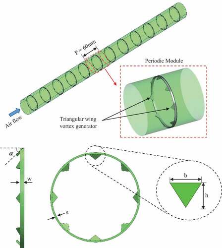
Table 1. Different configurations of triangular vortex generators
2.2. Governing equations and performance parameters
The following are the equations that characterize the flow and heat transmission in a steady, compressible, and turbulent flow (Zhang et al., Citation2020):
Continuity equation:
Momentum equation:
Energy equation:
The RNG k-ε turbulence model:
The following are the constant values used in the above equations,
C1є = 1.42, C2є = 1.68 and Cµ = 0.0845. Also, ,
, β = 0.012,
.
2.2.1. Nusselt number
The well-known Dittus-Boelter Equationequation [2](2)
(2) is used to determine the Nusselt number for smooth tube for fully developed turbulent flow conditions as follows:
For a circular tube heat exchanger consisting of vortex generators, the Nusselt number (Zhang et al., Citation2020) can be determined using the following expression:
Where, Tp is the average temperature of the tube surface and Tb is the bulk temperature of air stream.
2.2.2. Friction factor
The Blasius Equationequation [2](2)
(2) is used to evaluate the friction factor in a smooth tube and is given by,
The following Equationequation [2](2)
(2) is used to calculate the friction factor for a circular tube in the presence of a vortex generator:
2.2.3. Thermal enhancement factor
The thermal enhancement factor, which examines the relative gain of heat transfer and the pressure drop penalty to assess if the suggested design is actually advantageous for heat transfer enhancement, is used to evaluate the effective thermal performance. The TEF (Zhang et al., Citation2020) is calculated as follows:
2.3. Boundary conditions, assumptions and numerical schemes
The computational domain used in the present analysis is a fully developed periodic module of one pitch length of 60 mm as highlighted in , which significantly reduces the number of control volumes used for domain discretization as well as computational time and has been widely adopted by previous researchers as well (Chokphoemphun et al., Citation2015; M.s et al., Citation2021; Nanan et al., Citation2017; Promvonge et al., Citation2020; Skullong et al., Citation2018). A heat flux of 500 W/m2 was applied on the surface of the heat exchanger as per Zhang et al. (Citation2020). The air velocity at the intake varies between 1.77 m/s and 5.36 m/s corresponding to a flow Reynolds number of 6000–18,000. No-slip and impermeable wall conditions are used to define the contact between the solid wall and the fluid. As indicated in the experimental research of Zhang et al. (Citation2020), the walls of the insert and the vortex generator are characterised as adiabatic walls with no heat transfer assumed via their surface. It is assumed that the air flow through the tube is steady, incompressible and turbulent. The heat lost to the atmosphere by radiation and convection from the tube boundaries are ignored in the analysis. RNG k-ϵ turbulence model is used along with enhanced wall treatment to resolve the boundary layer region and is widely adopted by previous researchers to capture the flow turbulence characteristics (Chokphoemphun et al., Citation2015; Chamoli et al., Citation2017; M.s et al., Citation2021; Nakhchi & Esfahani, Citation2019; Promvonge et al., Citation2020; Zhang et al., Citation2020). The higher order QUICK scheme is used to discretize the governing equations. The convergence of solution is considered when the residuals are less than 10−6 for continuity, momentum and turbulence equations and 10−8 for energy equation. Ansys Fluent software tool is used for carrying out the numerical simulations.
2.4. Grid test and experimental validation
The present work is based on the experimental investigation of Zhang et al. (Citation2020) who made use of rectangular winglet vortex generators in a circular tube. The present work makes use of triangular wing vortex generator in place of rectangular geometry. Hence, the validation of results predicted by the present CFD formulation is carried out by comparing the CFD results for rectangular VG with that of the experimental results of Zhang et al. (Citation2020) for Nusselt number as well as friction factor. Since, the present work makes use of wing arrangement where the base of the vortex generator is always maintained perpendicular to the flow instead of winglet arrangement where the base can be tilted for other angles, the particular configuration of rectangular winglet VG where the flow attack angle is 90° to the incoming air stream is used for validation purpose. The geometric details of computational domain with rectangular VG is shown in (). The details of meshing used in the flow domain is shown in (). Tetrahedron volumes are used for discretization with inflation layers on the tube wall surface to capture the near wall effects. The authors in their previous publication (Kongkaitpaiboon, Nanan, Eiamsa-ard et al., Citation2010b) made use of the same computational domain with rectangular winglet vortex generators where the winglet inclination was maintained at 75°. A detailed grid independence study was conducted for this configuration and showed that a minimum of 865,475 control volumes are required to ensure grid-independent solution.
Figure 3. Details of (a) geometry of computational domain with rectangular vortex generator used in the experimental work of Zhang et al. (Zhang et al., Citation2020) having a flow attack angle (α) of 90° and (b) meshing used in the computational domain.
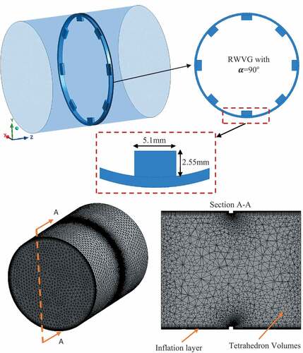
The present CFD model makes use of the same numerical schemes and boundary conditions as well as the geometric dimensions of the tube and ring insert except that the rectangular vortex generator is replaced by triangular vortex generator. A detailed grid test is further carried out for the case of triangular vortex generator to determine the minimum grid number above which the numerical solution becomes independent of grid number variation for the configuration having a flow attack angle of 90°, b/D = 0.137 and h/D = 0.0784 at Re = 18,000. Table shows the results obtained from the grid independence test. The number of control volumes are varied as 221,488, 497,615, 896,953 and 1,629,491 by varying the size of the tetrahedron control volume as well as the first layer thickness of inflation layer on the solid walls. The results show that the variation in Nusselt number and friction factor are lower than 1% as the number of control volumes are increased from 896,953 to 1,629,491. Hence, from the perspective of lower computer memory requirement and relatively faster computational time, all the computational models are ensured to contain at least 896,953 control volumes in the analysis.
Table 2. Grid Independence test results
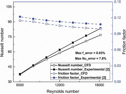
shows the comparison of present CFD results of Nusselt number and friction factor for rectangular wing vortex generator (RWVG) with an angle of attack of 90° with that of the corresponding experimental correlations of Zhang et al. (Citation2020) which are given below. The results show that the present CFD results are in close agreement with that of experimental Nusselt number and friction factor. The maximum relative error between the CFD and experimental results for Nusselt number and friction factor is about 7.8% and 8.03% respectively.
Figure 4. Comparison of experimental results of rectangular vortex generator (Zhang et al., Citation2020) with that of present CFD results for Nusselt number and friction factor for the flow attack angle of 90°.
Where,
LR = length ratio = (length of VG/tube diameter) = 0.1 and α = 90°.
3. Results and discussions
This sections brings out the influence of an array of triangular vortex generator insert on heat transfer and friction factor augmentation for air flow in a tubular heat exchanger. The effect of geometric parameters of TWVG on heat transfer and friction factor enhancement is determined for different Reynolds number range of 6000–18,000 and are presented under the following sections:
Effect of flow attack angle (α)
Effect of non-dimensional width (b/D)
Effect of non-dimensional height (h/D)
3.1. Effect of flow attack angle
The variation of Nusselt number enhancement for different flow attack angle of 22.5°, 45°, 67.5°, 90°, 112.5° and 135° for a fixed non-dimensional width and height ratio of 0.1372 and 0.0784 for the Reynolds number range of 6000–18,000 is shown in . Since, inclinations lower than 22.5° creates narrow regions between the vortex generator and the tube surface, the angle of 22.5° was chosen as the smallest flow attack angle. All other angles are varied as an increment of 22.5° on either side of the vortex generator. The Nusselt number enhancement is the ratio of Nusselt number (Nu) for TWVG and Nusselt number for smooth tube (Nus) which are determined using Equationequation (7)(7)
(7) and Equationequation (6)
(6)
(6) respectively. In general, the presence of TWVG is found to improve heat transfer as seen in where the enhancement in Nusselt number ranges between 1.4–1.8 times that of smooth tube. This is due to the significant flow structural changes brought in by the vortex generator which augments flow mixing in the vicinity of tube wall. An insight into the flow pathlines (coloured by air temperature) can be useful to reveal the flow variations around the TWVG as shown in () for the flow attack angle of 22.5°. The pathlines reveal that the air flow path is significantly altered around the vortex generator region which cause variations in heat energy exchange between the tube wall and air stream. The incoming air stream impacts the TWVG surface and gets deflected towards the base of the vortex generator causing flow impingement effect. The air stream from the core region which is relatively colder is therefore brought in direct contact with the heated tube wall at the vortex generator base region leading to enhanced heat transfer in all such regions. A look at the Nusselt number distribution on the tube wall as shown in () for the flow attack angle of 22.5° clearly reveals this aspect where enhanced Nusselt number regions are observed on the immediate front side of the vortex generator. As the air stream passes over the inclined edges of TWVG, longitudinal vortices are formed as shown by flow pathlines in ().
Figure 5. Variation of Nusselt number enhancement for different flow attack angle of TWVG for the geometrical configuration having h/D = 0.0784 and b/D = 0.1372.
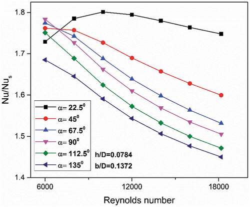
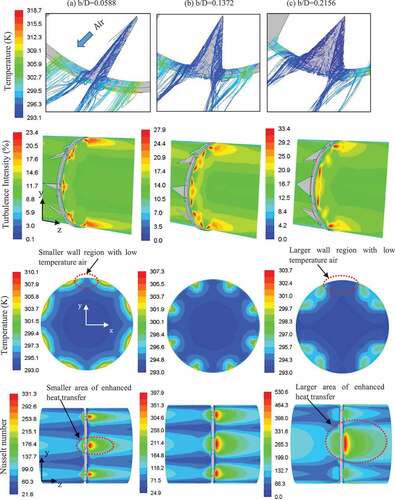
Figure 6. Comparison of flow pathlines (coloured by temperature), temperature distribution on a transverse plane at z = 32 mm from inlet, turbulence intensity (%) and Nusselt number on the tube wall for different flow attack angle of (a) 22.5° (b) 90° and (c) 135° for the TWVG configuration having h/D = 0.0784 and b/D = 0.1372.
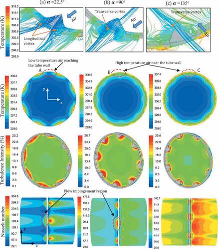
These longitudinal vortices provide rigorous flow mixing near the tube wall region and brings the colder air stream from the core region in direct contact with the heated tube wall region. A look into the variation of temperature at a transverse plane which is taken at a distance of z = 32 mm from the tube inlet as shown in () clearly reveals the flow of low temperature air stream towards the tube wall in the downstream region of TWVG. As a result, the temperature gradient increases near the tube wall region leading to augmented heat transfer. The longitudinal vortices are seen to move along the tube wall for some distance before it diminishes. As a result, there exists greater area of tube wall that is in contact with longitudinal vortices that exhibit enhanced heat transfer. This can be seen from the Nusselt number distribution plots in () where enhanced heat transfer is observed in the downstream region of each TWVG for some distance along the tube. It is noted that the peak heat transfer also occurs in this region owing to intense flow mixing of near wall flow and the core air stream. A look into the distribution of turbulence intensity at a transverse plane (at z = 32 mm) which is just behind the TWVG shows the presence of significant levels of turbulence very close to the heated tube wall. The appearance of peak heat transfer in the downstream region is related to the presence of enhanced flow mixing effect. Thus, the presence of flow impingement effect on the upstream side of the TWVG and the formation of longitudinal vortices that are characterised by enhanced turbulence levels in the downstream region is found to provide increased heat transfer from the heated tube wall. The extent to which the presence of flow impingement effect as well as longitudinal vortices impact the heat transfer process is dependent on the geometrical configurations of the TWVG as well as on the flow attack angle.
Further, from , it is clearly seen that the Nusselt number improvement is higher for lower flow attack angle and the maximum improvement in heat transfer is observed for α = 22.5°. This can be due to varying levels of flow impingement effect, flow turbulence levels as well as the nature of vortices formed around the TWVG for different flow attack angles. shows a detailed comparison of flow pathlines, temperature distribution on a plane just behind the vortex generator inserts which is at a distance of 32 mm from the inlet, turbulence intensity and Nusselt number distribution on the tube wall for the flow attack angles of 22.5°, 90° and 135° for the geometric configuration of h/D = 0.0784 and b/D = 0.1372. From the pathlines, it is clearly seen that the flow structure changes significantly as the angle of attack increases from 22.5° to 90°. The flow impingement effect is more pronounced for α = 90° owing to greater frontal area exposure to the incoming flow which causes increased flow deflection onto the vortex generator base region. As a result, relatively more air stream is deflected towards the vortex generator base region thereby causing increased heat energy exchange. This is clearly seen from the Nusselt number plot in () where the heat transfer is at its peak on the front side of the TWVG.
Further, as the air stream passes over the vortex generator, it forms transverse vortices on the downstream side as shown by the pathlines and are seen to exhibit higher turbulence levels around the TWVG. However, the influence of these vortices are limited only to a small region near the vortex generator in the downstream region which is in contrast to that of α = 22.5° which exhibits longitudinal vortices that move away for some distance in the flow direction thereby covering relatively larger tube wall region. In addition, the temperature contour map reveals that the tube wall region is in contact with relatively higher temperature air which reduces the temperature gradient thereby limiting the heat transfer as compared to that of 22.5°. As the flow attack angle increases to 135°, the flow pathlines of () show that the flow impingement effect diminishes significantly as the TWVG is now more streamlined to the incoming flow. The air stream glides over the TWVG surface and create transverse vortices on the immediate downstream as seen in the pathline plot. An interesting observation is that for the flow attack angle of 135°, the TWVG deflects some of the relatively colder incoming flow away towards the core flow region instead of pushing them closer to the tube wall. As a result, the transverse vortices formed behind the vortex generator causes flow mixing of air stream that are within the region close to the tube wall. This is corroborated by the presence of relatively high temperature air around the vortex generator in the temperature distribution plot in (), which significantly limits the heat energy exchange. In addition, the turbulence intensity is found to be slightly lower and also exhibit high turbulence intensity over a narrow region around the TWVG.
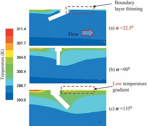
shows the comparison of temperature distribution around the VG in the flow direction taken at a central plane. It is clearly revealed that for α = 22.5°, the colder air stream is made to reach the tube wall region on both the upstream and downstream side of the VG which causes boundary layer thinning. On the contrary, for α = 135°, the incoming air stream is deflected away from the tube wall as is clearly seen by the presence of high temperature air on the downstream side where the temperature gradients are relatively lower. Thus, the heat transfer it found to decrease with increasing flow attack angle owing to reduced flow impingement effect and the formation of weaker transverse vortices in the downstream region of VGT.
Figure 7. Comparison of temperature distribution around the TWVG in the flow direction at the central plane for different flow attack angle.
The flow attack angle also influences the pressure drop in the air flow across the tube since the TWVG cause flow obstruction irrespective of the flow attack angle. shows the comparison of friction factor for different flow attack angles at varying Reynolds number. Interestingly, the friction factor increases with flow attack angle from 22.5° to 90° and drops thereafter. For α = 22.5°, the TWVG is inclined much towards the tube wall and does not expose large frontal area for impact with the incoming air stream. However, as the angle of attack increases, the TWVG surface will be increasingly aligned in the direction normal to the flow thereby causing greater flow obstruction and hence greater pressure energy loss. Therefore, the friction factor is found to increase from α = 22.5° to α = 90°. However, for α > 90°, the TWVG is now inclined backwards thereby aligning itself in the air flow direction. This reduces the flow obstruction effect and the friction factor reduces as result of reduced pressure energy loss.
Figure 8. Comparison of friction factor enhancement for different flow attack angle of TWVG for the geometrical configuration having h/D = 0.0784 and b/D = 0.1372.
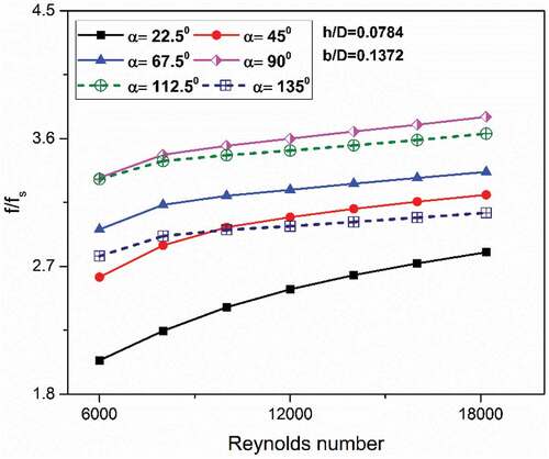
Thus, the flow attack angle of 22.5° is found to exhibit greater heat transfer augmentation with lower friction factor penalty. The following sections make use of α = 22.5° for determining the influence of geometric parameters of TWVG on the overall thermal performance of tubular heat exchanger.
3.2. Effect of non-dimensional width (b/D)
The effect of variation of non-dimensional width of TWVG on Nusselt number enhancement for different flow Reynolds number and fixed non-dimensional height of h/D = 0.3137 and α = 22.5° is shown in . The variation of base width of TWVG is seen to significantly influence the heat transfer process as indicated in with higher width showing greater improvement in heat transfer.
Figure 9. Variation of Nusselt number enhancement for different non-dimensional width of TWVG for the geometrical configuration having h/D = 0.3137 and α = 22.5°.
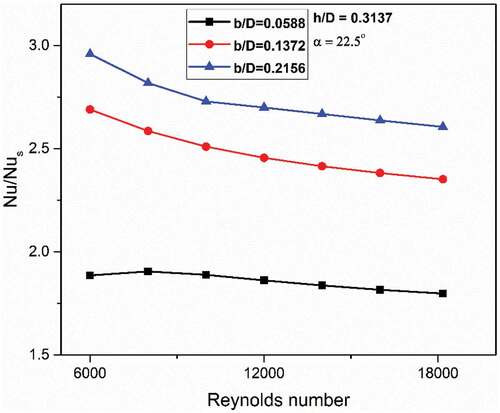
A look into the flow pathlines as shown in () for b/D = 0.0588 to () for b/D = 0.2156 shows a general trend of the formation of longitudinal vortices on the downstream side which is characteristic of low flow attack angle of α = 22.5° as seen in the previous section. However, the difference lies in the size and strength of these vortices which dictates the extent of heat energy transfer. The flow pathlines clearly show that larger base width of TWVG enlarges the area of contact of longitudinal vortices on the tube wall behind the TWVG thereby allowing greater heat extraction. It is also noted that the TWVG gets bigger in size and will be able to cause greater flow interference. This is clearly seen in turbulence intensity distribution plot in () where the turbulence intensity is at a relatively lower level and has narrow region of influence around the TWVG at lower width. The turbulence intensity rises considerably as the TWVG gets bigger and region of influence of higher turbulence intensity also gets wider at the TWVG base and deeper into the core region as shown by the turbulence intensity distribution plots. An important outcome of this change in flow structure is the increased presence of core flow near the tube wall region as revealed by the temperature distribution plots in () to (). Bigger TWVG is able to push greater colder air stream from the main flow towards the heated tube wall region as indicated by the presence of low temperature air stream in the temperature contour plots. The regions of enhanced heat transfer on the tube wall can be clearly seen from the Nusselt number contour plots as width varies from b/D = 0.0588 to b/D = 0.2156. The Nusselt number is seen to be at its peak on the immediate downstream of the TWVG for all the base width of TWVG. In addition, the Nusselt number is also found to be higher at the immediate upstream region of TWVG for all the cases. The presence of longitudinal vortices cause enhance heat transfer on the downstream region while the flow impingement enhance heat transfer in the region upfront of TWVG. The major difference is that these regions that exhibit augmented heat transfer gets bigger as the base width increases thereby leading to increased heat energy exchange. Not only the size of these regions are bigger, but also the magnitude of enhancements achieved in terms of turbulence intensity as well as Nusselt number which are significantly higher for increased base width. The Nusselt number enhancement is found to be in the range of 1.885–1.797 for b/D = 0.0588, 2.689–2.351 for b/D = 0.1372 and 2.958–2.606 for b/D = 0.2156.
Figure 10. Comparison of flow pathlines (coloured by temperature), temperature distribution on a transverse plane at X = 32 mm from inlet, turbulence intensity (%) and Nusselt number on the tube wall for different non-dimensional width of (a) b/D = 0.0588 (b) b/D = 0.1372 and (c) b/D = 0.2156 for the TWVG configuration having h/D = 0.3137 and α = 22.5°.
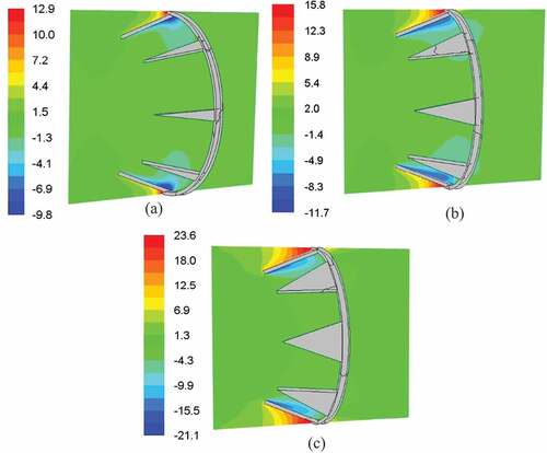
As the TWVG gets bigger, the pressure drop across the tube also gets impacted as indicated by greater friction factor enhancement for increasing values of b/D in . Since, the TWVG gets bigger for larger base width, the flow interference will also be greater which causes increased pressure drop. shows the comparison of pressure distribution which clearly shows greater pressure difference across the TWVG inserts. As the flow impacts with the TWVG, the pressure rises locally on the upstream side and hence larger pressure regions are seen upfront of the inserts. On the downstream side, due to flow separation and intense vortex formation, the local pressure drops leading to pressure differential across the TWVG. The extent of this pressure drop depends on the size of the TWVG. The flow separation takes place due to the presence of ring insert which disrupts the boundary layer causing flow detachment from the tube surface. The flow separation predominantly occurs in the flow region between the vortex generators on the ring insert. As is clearly seen from the pressure contour plots, the pressure differential is larger for larger base width and hence the friction factor is also higher as indicated in . The friction factor enhancement is in the range of 2.484–3.045 for b/D = 0.0588, 4.546–5.535 for b/D = 0.1372 and 6.545–8.101 for b/D = 0.2156.
Figure 11. Variation of friction factor enhancement for different non-dimensional width of TWVG for the geometrical configuration having h/D = 0.3137 and α = 22.5°.
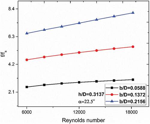
Figure 12. Comparison of pressure distribution in the air flow across the TWVG for (a) b/D = 0.0588, (b) b/D = 0.1372, (c) b/D = 0.2156 for the geometrical configuration of TWVG having h/D = 0.3137 and α = 22.5°.
3.3. Effect of non-dimensional height (h/D)
The effect of variation of non-dimensional height of TWVG on Nusselt number enhancement for different flow Reynolds number and fixed non-dimensional width of b/D = 0.1372 and α = 22.5° is shown in . Greater enhancement in Nusselt number is observed for greater height of TWVG for all the flow rates used in the analysis. Greater the height, greater is the protrusion of TWVG into the main flow as seen in the flow pathlines in . As a result, for lower height the TWVG interferes only with the flow close to the tube wall that is characterised by the presence of relatively high temperature air as seen in the pathlines in (). As a result, relatively hot air is pushed towards the heated tube wall. This is also very clearly shown in the temperature distribution plot in (). Moreover, the vortices formed on the downstream side is smaller in size and have limited coverage on the tube wall region which in turn limits the augmentation of heat transfer. In addition, only a narrow region around the TWVG exhibits higher turbulence levels owing to lower levels of flow interference by shorter TWVG. As the height increases, the TWVG protrude more into the air stream region and deflect colder air stream towards the tube wall for flow impingement on the upstream side and for longitudinal vortex formation on the downstream side as seen in (). As a consequence, the flow turbulence levels are found to be at elevated levels for relatively large region on the downstream side of the TWVG as seen in () and (). This further leads to increased heat energy exchange between the heated tube wall and the air stream. The Nusselt number contour plots reveal that the flow impingement region is much smaller in size for lower height. In addition, the regions that exhibit enhanced heat transfer on the downstream side is also smaller as seen in () for lower height. For higher non-dimensional height, both these regions are seen to enlarge thereby exhibiting greater tube wall regions at which heat transfer is at elevated levels. The Nusselt number enhancement is found to be in the range of 1.571–1.531 for h/D = 0.0392, 1.892–1.83 for h/D = 0.0784, 2.339–2.157 for h/D = 0.1568, 2.573–2.28 for h/D = 0.235 and 2.689–2.351 for h/D = 0.3137. Thus, greater height is found to provide higher heat enhancements in heat transfer. However, the corresponding friction factor penalty is also found to rise accordingly. The variation of friction factor for different TWVG height is shown in . The friction factor is found to increase monotonously for increasing height of the TWVG. Greater height of TWVG results in enhanced levels of friction factor penalty owing to higher pressure energy loss across the tube. Thus, the effective thermal performance needs to be looked into considering both the aspects of friction factor and heat transfer improvement in order to identify the useful range and geometric parameters of TWVG and the following section highlights this aspect for the results obtained in the above three sections. The Nusselt number and friction factor enhancement obtained for various configurations of TWVG used in the analysis is given in Table and Table respectively. It is observed that the highest increase in Nusselt number is achieved by the TWVG configuration having b/D = 0.216 and h/D = 0.314 and is about 2.96 at Re = 6000. The highest increase in friction factor is about 8.1 times that of smooth tube for the TWVG configuration having b/D = 0.216 and h/D = 0.314 at Re = 18,000.
Figure 13. Variation of Nusselt number enhancement for different non-dimensional height of TWVG the geometrical configuration having b/D = 0.1372 and α = 22.5°.
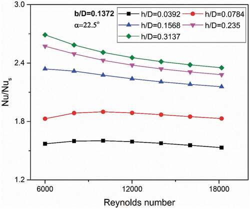
Figure 14. Comparison of flow pathlines (coloured by temperature), temperature distribution on a transverse plane at X = 32 mm from inlet, turbulence intensity (%) and Nusselt number on the tube wall for different non-dimensional width of (a) h/D = 0.0392, (b) h/D = 0.1568 and (c) h/D = 0.3137 for the TWVG configuration having b/D = 0.1372 and α = 22.5°.
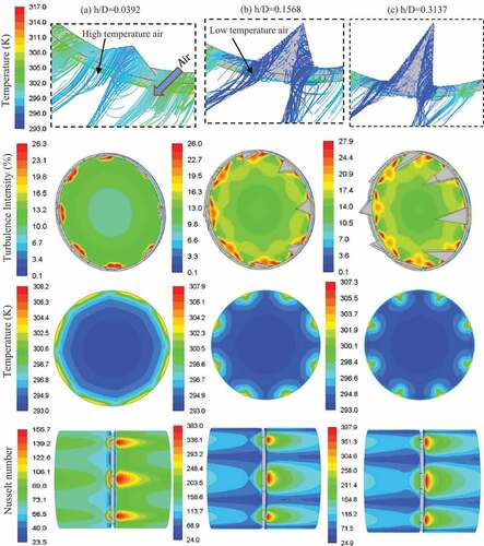
Figure 15. Variation of friction factor enhancement for different non-dimensional height of TWVG the geometrical configuration having b/D = 0.1372 and α = 22.5°.
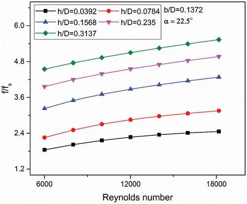
Table 3. Nusselt number enhancement for various configurations of TWVG
Table 4. Friction factor enhancement for various configurations of TWVG
3.4. Thermal enhancement factor
The effective thermal performance which considers the relative gain of heat transfer enhancement over the friction factor penalty is determined by the commonly used thermal enhancement factor (TEF) and is given by Equationequation (10)(10)
(10) . The configurations that provide the TEF>1 are considered to be truly beneficial in providing augmented heat transfer despite the friction factor penalty. All other configurations that exhibit TEF<1 indicates that the pressure drop is overwhelmingly high relative to the heat transfer gain and are not recommended for use. Since, the TEF is a ratio of heat transfer enhancement to friction factor enhancement, any configuration of vortex generator which exhibits TEF<1 indicates that the friction factor enhancement is relatively higher than that of heat transfer gain. If the TEF ≪1, then the friction factor enhancement is significantly greater as compared to that of corresponding heat transfer gain thereby rendering the respective TWVG configuration useless. Therefore, greater the TEF, better the configuration is from the perspective of overall heat transfer.
shows the variation of TEF for different flow attack angle of TWVG for the geometrical configuration having h/D = 0.0784 and b/D = 0.1372. It is seen that the flow attack angle of 22.5° provides higher TEF than all other angle of attack used in the analysis. The TEF for α = 22.5° is found to be in the range of 1.39–1.25 while the lowest TEF is in the range of 0.96–1.17 for α = 112.5°. This is due higher heat transfer enhancement capability exhibited by α = 22.5° for all
Figure 16. Comparison of TEF for different flow attack angle of TWVG having b/D = 0.1372 and h/D = 0.0784.
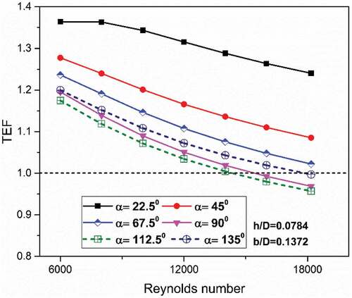
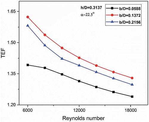
flow Reynolds number adopted in the analysis with corresponding lower friction factor penalty. The configuration of α = 22.5° exhibits about 17.54% higher heat transfer on an average with about 20.63% lower friction factor penalty as compared to α = 112.5°. The presence of flow impingement and the formation of longitudinal vortices with lower frontal impact with the incoming flow ensures that the heat transfer augmentation takes place with lower pressure drop penalty. More importantly, the TEF is found to be significantly greater than 1 for all the flow rates used in the analysis. shows the comparison of TEF for different non-dimensional width of TWVG for a given height of h/D = 0.3137 and α = 22.5°. The TEF is seen to increase as base width of TWVG increases from b/D = 0.059 to 0.137 and drops slightly thereafter. The TEF for b/D = 0.059 varies between 1.39 and 1.24 while that for b/D = 0.137 is in the range of 1.62–1.33. Although the average friction factor enhancement for lower base width configuration is about 44.65% lower than b/D = 0.137, the corresponding average enhancement in heat transfer is about 25.2% lower. However, there is negligible different in the TEF between the configuration of b/D = 0.137 and 0.216. This is interesting since the heat transfer for b/D = 0.216 is about 9% lower than b/D = 0.216. However, the average rise in friction factor penalty is significantly lower by about 31%. This shows that for a given h/D ratio, the base width ratio of 0.137 provides maximum TEF for the flow rate corresponding to Re = 6000–18,000.
Figure 17. Comparison of TEF for different non-dimensional width of TWVG for the geometrical configuration having h/D = 0.3137 and α = 22.5°.
shows the comparison of TEF for different non-dimensional height of TWVG for the geometrical configuration having b/D = 0.1372 and α = 22.5°. Larger height is found to provide higher TEF as the height increases from 0.039 to 0.157. However, a further rise in the height of TWVG does insignificant change in the effective thermal performance even after doubling the TWVG height from 0.157 to 0.235. This is because, for the case of h/D = 0.157, although the average heat transfer improvement is about 6.8% lower than that of h/D = 0.235, the friction factor rise is considerably lower by about 18.3%. The maximum TEF is produced by the configuration having h/D = 0.235 and has a range of 1.34–1.63. A further rise in the non-dimensional height is found to have negligible impact on the TEF performance, although the TEF shows a downward trend. Table lists the TEF obtained for all the configurations used in the analysis. The configuration of b/D = 0.137 and h/D = 0.235 provides the highest TEF among all the configurations used for the Reynolds number range of 6000–18,000.
Figure 18. Comparison of TEF for different non-dimensional height of TWVG the geometrical configuration having b/D = 0.1372 and α = 22.5°.
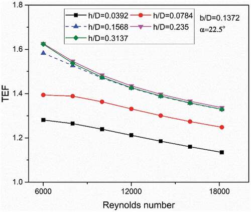
Table 5. TEF for various configurations of TWVG
3.5. Comparison with previous works
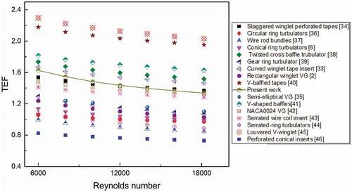
A comparison of effective thermal performance of present work is made with the previous reported works such as staggered winglet tape inserts (Skullong et al., Citation2016), semi-elliptical VG (M.s et al., Citation2021), circular ring turbulators (Kongkaitpaiboon, Nanan, Eiamsa-ard et al., Citation2010b), wire rod bundle inserts (Nanan et al., Citation2013), conical ring inserts (Ibrahim et al., Citation2019), twisted cross baffle turbulators (Nanan et al., Citation2017), gear ring turbulator (Ruengpayungsak et al., Citation2017), curved winglet tape inserts (Skullong et al., Citation2018), rectangular winglet VG (Zhang et al., Citation2020), V-baffled tape (Promvonge & Skullong, Citation2020), V-shaped baffles (Promvonge & Skullong, Citation2021), NACA0024 VG (Gururatana et al., Citation2021), serrated wire coil insert (Chompookham et al., Citation2022), serrated-ring turbulators (Pimsarn et al., Citation2021), louvered V-winglet (Promvonge et al., Citation2022) and perforated conical inserts (Srivastava et al., Citation2021) for different Reynolds number as shown in . The triangular wing vortex generators used in the present work is found to provide higher TEF than ring turbulators, gear ring inserts and wire rod bundles owing to relatively lower friction factor enhancement due to reduced flow blockage as the TWVG is placed intermittently on the tube wall. In addition, the TWVG provides longitudinal vortices in comparison to the transverse vortices which provides greater heat transfer augmentation. The present configuration also provides improved TEF over the multiple rectangular winglet as well as semi-elliptical winglet vortex generators on the basis of which the present work is undertaken. The TEF of present TWVG is about 30.5% higher as compared to the multiple rectangular winglet VG. On the other hand, the TEF performance of TWVG is closer to that of staggered winglet perforated tape inserts and curved winglet tape inserts. Thus, the triangular vortex generator used in the present work provides significant TEF performance over most of the previously reported vortex generator designs.
Figure 19. Comparison of TEF performance of present work with that of existing configurations of vortex generators.
4. Conclusions
A three dimensional numerical analysis is carried out to determine the heat transfer and friction factor characteristics of triangular wing vortex generator in a circular tube heat exchanger for different flow Reynolds number range of 6000–18,000. The effect of base width, height of triangle and flow attack angle is investigated to determine the best configurations that provide augmented TEF performance. The following are the major conclusions from the analysis:
The TWVG augments heat transfer through flow impingement effect on the upstream side and vortex formation on the downstream side.
The flow impingement effect is prominently seen for α = 90° as compared to other flow attack angles owing to greater flow deflection effect.
For α = 22.5°, longitudinal vortices are formed on the downstream side which are found to cause rigorous flow mixing leading to boundary layer thinning close to the tube wall. On the contrary, transverse vortices are formed for all other flow attack angles used in the analysis which are found to have lower flow mixing effect as well as lower coverage of tube wall region.
The heat transfer is found to increase with increasing flow attack angle. However, the friction factor is found to increase from α = 22.5° to α = 90°. For α > 90°, friction factor reduces as a result of increased streamlined orientation of vortex generator to the air stream.
For a given height, larger base width provides greater heat transfer and friction factor enhancement. For a given base width, larger height provides greater heat transfer and friction factor enhancement. The maximum enhancement in Nusselt number and friction factor is in the range of 2.61–2.96 and 6.54–8.1 respectively for b/D = 0.216 and h/D = 0.314.
The maximum TEF is produced by the configuration having h/D = 0.235 and b/D = 0.059 and has a range of 1.34–1.63.
Nomenclature
Notation Description
| Gk | = | Generation of turbulence kinetic energy |
| Nus, Nu | = | Nusselt number for smooth tube and roughened tube |
| Δp | = | Pressure drop across the tube, Pa |
| K | = | Air thermal conductivity, WmK−1 |
| Pr | = | Prandtl number |
| T | = | Temperature, K |
| Q’ | = | Heat flux on the tube wall, Wm−2 |
| V | = | Mean air velocity, ms−1 |
| fs, f | = | Friction factor for smooth tube and roughened tube |
| h | = | Convective heat transfer coefficient, Wm−2K |
| k | = | Turbulence kinetic energy, m2s−2 |
| u | = | Velocity component, ms−1 |
Greek Symbols
| µt | = | Turbulent viscosity, Nsm−2 |
| Г | = | Molecular thermal diffusivity, m2s−1 |
| Гt | = | Turbulent thermal diffusivity, m2s−1 |
| є | = | Rate of dissipation, m2s−3 |
Acknowledgements
The authors wish to express their gratitude and acknowledge the computational facilities provided by the Department of Mechanical and Industrial Engineering, Manipal Institute of Technology, MAHE, Manipal in carrying out this research work. This research did not receive any specific grant from any funding agencies.
Disclosure statement
No potential conflict of interest was reported by the author(s).
Additional information
Funding
Notes on contributors
Manjunath M S
Manjunath M S is an academician with an experience of over 13 years in teaching undergraduate and post-graduate students in Mechanical engineering and has a Doctoral degree in Thermal Engineering. The key research activities carried out by the author and his group include experimental and computational investigations for heat transfer enhancement in solar air heaters, heat exchangers and solar distillation systems. The present research findings are very useful in the application of tubular heat exchangers which provides enhanced heat transfer with limited flow energy loss by making use of specially designed triangular vortex generator inserts. Poor heat transfer in heat exchangers often leads to wastage of precious energy which needs to be resolved to ensure energy conservation. The proposed inserts have been shown to significantly enhance heat transfer capability of tubular heat exchanger.
References
- Bali, T., & Sarac, B. A. (2014, April). Experimental investigation of decaying swirl flow through a circular pipe for binary combination of vortex generators. International Communications in Heat and Mass Transfer, 53, 174–30. https://doi.org/10.1016/j.icheatmasstransfer.2014.02.030
- Bhuiya, M. M. K., Chowdhury, M. S. U., Saha, M., & Islam, M. T. (2013, August). Heat transfer and friction factor characteristics in turbulent flow through a tube fitted with perforated twisted tape inserts. International Communications in Heat and Mass Transfer, 46, 49–57. https://doi.org/10.1016/j.icheatmasstransfer.2013.05.012
- Chamoli, S., Lu, R., & Yu, P. (2017, July). Thermal characteristic of a turbulent flow through a circular tube fitted with perforated vortex generator inserts. Applied Thermal Engineering, 121, 1117–1134. https://doi.org/10.1016/j.applthermaleng.2017.03.145
- Chokphoemphun, S., Pimsarn, M., Thianpong, C., & Promvonge, P. (2015, April). Heat transfer augmentation in a circular tube with winglet vortex generators. Chinese Journal of Chemical Engineering, 23(4), 605–614. https://doi.org/10.1016/j.cjche.2014.04.002
- Chompookham, T., Chingtuaythong, W., & Chokphoemphun, S. (2022, January). Influence of a novel serrated wire coil insert on thermal characteristics and air flow behavior in a tubular heat exchanger. International Journal of Thermal Sciences, 171, 107184. https://doi.org/10.1016/j.ijthermalsci.2021.107184
- Dang, W., & Wang, L.-B. (2021, April). Convective heat transfer enhancement mechanisms in circular tube inserted with a type of twined coil. International Journal of Heat and Mass Transfer, 169, 120960. https://doi.org/10.1016/j.ijheatmasstransfer.2021.120960
- Eiamsa-ard, S., Pethkool, S., Thianpong, C., & Promvonge, P. (2008, February). Turbulent flow heat transfer and pressure loss in a double pipe heat exchanger with louvered strip inserts. International Communications in Heat and Mass Transfer, 35(2), 120–129. https://doi.org/10.1016/j.icheatmasstransfer.2007.07.003
- Eiamsa-ard, S., & Promvonge, P. (2006, May). Experimental investigation of heat transfer and friction characteristics in a circular tube fitted with V-nozzle turbulators. International Communications in Heat and Mass Transfer, 33(5), 591–600. https://doi.org/10.1016/j.icheatmasstransfer.2006.02.022
- Gururatana, S., Prapainop, R., Chuepeng, S., & Skullong, S. (2021, August). Development of heat transfer performance in tubular heat exchanger with improved NACA0024 vortex generator. Case Studies in Thermal Engineering, 26, 101166. https://doi.org/10.1016/j.csite.2021.101166
- Hakim, M. U., Hridoy, M. W., Islam, M. I., & Rayhan, M. S., “Numerical study of heat transfer enhancement through a circular tube fitted with and without rectangular cut twisted tape insert,” IOP Conference Series: Materials Science and Engineering Nov 5-6 Jaipur, India, vol. 1017 (IOP Publishing Ltd), p. 012019, January. 2021, https://doi.org/10.1088/1757-899X/1017/1/012019.
- Huang, W.-C., Chen, C.-A., Shen, C., & San, J.-Y. (2015, November). Effects of characteristic parameters on heat transfer enhancement of repeated ring-type ribs in circular tubes. Experimental Thermal and Fluid Science, 68, 371–380. https://doi.org/10.1016/j.expthermflusci.2015.06.007
- Ibrahim, M. M., Essa, M. A., & Mostafa, N. H. (2019, March). A computational study of heat transfer analysis for a circular tube with conical ring turbulators. International Journal of Thermal Sciences, 137, 138–160. https://doi.org/10.1016/j.ijthermalsci.2018.10.028
- Keklikcioglu, O., & Ozceyhan, V. (2018, February). Experimental investigation on heat transfer enhancement in a circular tube with equilateral triangle cross sectioned coiled-wire inserts. Applied Thermal Engineering, 131, 686–695. https://doi.org/10.1016/j.applthermaleng.2017.12.051
- Kongkaitpaiboon, V., Nanan, K., & Eiamsa-ard, S. (2010a, May). Experimental investigation of heat transfer and turbulent flow friction in a tube fitted with perforated conical-rings. International Communications in Heat and Mass Transfer, 37(5), 560–567. https://doi.org/10.1016/j.icheatmasstransfer.2009.12.015
- Kongkaitpaiboon, V., Nanan, K., & Eiamsa-ard, S. (2010b, May). Experimental investigation of convective heat transfer and pressure loss in a round tube fitted with circular-ring turbulators. International Communications in Heat and Mass Transfer, 37(5), 568–574. https://doi.org/10.1016/j.icheatmasstransfer.2009.12.016
- Lei, Y., Zheng, F., Song, C., & Lyu, Y. (2017, August). Improving the thermal hydraulic performance of a circular tube by using punched delta-winglet vortex generators. International Journal of Heat and Mass Transfer, 111, 299–311. https://doi.org/10.1016/j.ijheatmasstransfer.2017.03.101
- Lin, Z.-M., Wang, L.-B., Lin, M., Dang, W., & Zhang, Y.-H. (2017, March). Numerical study of the laminar flow and heat transfer characteristics in a tube inserting a twisted tape having parallelogram winglet vortex generators. Applied Thermal Engineering, 115, 644–658. https://doi.org/10.1016/j.applthermaleng.2016.12.142
- Liu, P., Zheng, N., Shan, F., Liu, Z., & Liu, W. (2018, December). Heat transfer enhancement for laminar flow in a tube using bidirectional conical strip inserts. International Journal of Heat and Mass Transfer, 127, 1064–1076. https://doi.org/10.1016/j.ijheatmasstransfer.2018.07.128
- M.s, M., Fernandes, D. V., & Pham, D. T. (2021, January). Numerical investigation of heat transfer and friction factor characteristics of circular tube fitted with an array of semi-elliptical vortex generator inserts. Cogent Engineering, 8(1). https://doi.org/10.1080/23311916.2021.1968742
- Man, C., Lv, X., Hu, J., Sun, P., & Tang, Y. (2017, March). Experimental study on effect of heat transfer enhancement for single-phase forced convective flow with twisted tape inserts. International Journal of Heat and Mass Transfer, 106, 877–883. https://doi.org/10.1016/j.ijheatmasstransfer.2016.10.026
- Nakhchi, M. E., & Esfahani, J. A. (2019, June). Numerical investigation of different geometrical parameters of perforated conical rings on flow structure and heat transfer in heat exchangers. Applied Thermal Engineering, 156, 494–505. https://doi.org/10.1016/j.applthermaleng.2019.04.067
- Nakhchi, M. E., Esfahani, J. A., & Kim, K. C. (2020, February). Numerical study of turbulent flow inside heat exchangers using perforated louvered strip inserts. International Journal of Heat and Mass Transfer, 148, 119143. https://doi.org/10.1016/j.ijheatmasstransfer.2019.119143
- Nanan, K., Pimsarn, M., Jedsadaratanachai, W., & Eiamsa-ard, S. (2013, November). Heat transfer augmentation through the use of wire-rod bundles under constant wall heat flux condition. International Communications in Heat and Mass Transfer, 48, 133–140. https://doi.org/10.1016/j.icheatmasstransfer.2013.08.021
- Nanan, K., Thianpong, C., Pimsarn, M., Chuwattanakul, V., & Eiamsa-ard, S. (2017, March). Flow and thermal mechanisms in a heat exchanger tube inserted with twisted cross-baffle turbulators. Applied Thermal Engineering, 114, 130–147. https://doi.org/10.1016/j.applthermaleng.2016.11.153
- Pimsarn, M., Samruaisin, P., Eiamsa-ard, P., Koolnapadol, N., Promthaisong, P., & Eiamsa-ard, S. (2021, December). Enhanced forced convection heat transfer of a heat exchanger tube utilizing serrated-ring turbulators. Case Studies in Thermal Engineering, 28, 101570. https://doi.org/10.1016/j.csite.2021.101570
- Pourhedayat, S., Pesteei, S. M., Ghalinghie, H. E., Hashemian, M., & Ashraf, M. A. (2020, April). Thermal-exergetic behavior of triangular vortex generators through the cylindrical tubes. International Journal of Heat and Mass Transfer, 151, 119406. https://doi.org/10.1016/j.ijheatmasstransfer.2020.119406
- Pourramezan, M., & Ajam, H. (2016, July). Modeling for thermal augmentation of turbulent flow in a circular tube fitted with twisted conical strip inserts. Applied Thermal Engineering, 105, 509–518. https://doi.org/10.1016/j.applthermaleng.2016.03.029
- Promvonge, P., Promthaisong, P., & Skullong, S. (2020, April). Experimental and numerical heat transfer study of turbulent tube flow through discrete V-winglets. International Journal of Heat and Mass Transfer, 151, 119351. https://doi.org/10.1016/j.ijheatmasstransfer.2020.119351
- Promvonge, P., Promthaisong, P., & Skullong, S. (2022, January). Thermal performance augmentation in round tube with louvered V-winglet vortex generator. International Journal of Heat and Mass Transfer, 182, 121913. https://doi.org/10.1016/j.ijheatmasstransfer.2021.121913
- Promvonge, P., & Skullong, S. (2020, September). Augmented heat transfer in tubular heat exchanger fitted with V-baffled tapes. International Journal of Thermal Sciences, 155, 106429. https://doi.org/10.1016/j.ijthermalsci.2020.106429
- Promvonge, P., & Skullong, S. (2021, February). Enhanced thermal performance in tubular heat exchanger contained with V-shaped baffles. Applied Thermal Engineering, 185, 116307. https://doi.org/10.1016/j.applthermaleng.2020.116307
- Ruengpayungsak, K., Wongcharee, K., Thianpong, C., Pimsarn, M., Chuwattanakul, V., & Eiamsa-ard, S. (2017, August). Heat transfer evaluation of turbulent flows through gear-ring elements. Applied Thermal Engineering, 123, 991–1005. https://doi.org/10.1016/j.applthermaleng.2017.05.108
- Skullong, S., Promvonge, P., Thianpong, C., & Jayranaiwachira, N. (2017, March). Thermal behaviors in a round tube equipped with quadruple perforated-delta-winglet pairs. Applied Thermal Engineering, 115, 229–243. https://doi.org/10.1016/j.applthermaleng.2016.12.082
- Skullong, S., Promvonge, P., Thianpong, C., Jayranaiwachira, N., & Pimsarn, M. (2018, January). Thermal performance of heat exchanger tube inserted with curved-winglet tapes. Applied Thermal Engineering, 129, 1197–1211. https://doi.org/10.1016/j.applthermaleng.2017.10.110
- Skullong, S., Promvonge, P., Thianpong, C., & Pimsarn, M. (2016, April). Heat transfer and turbulent flow friction in a round tube with staggered-winglet perforated-tapes. International Journal of Heat and Mass Transfer, 95, 230–242. https://doi.org/10.1016/j.ijheatmasstransfer.2015.12.007
- Srivastava, G. P., Patil, A. K., & Kumar, M. (2021, August). Heat transfer enhancement and entropy generation analysis of a tube with perforated conical inserts. Experimental Heat Transfer, 1–20. https://doi.org/10.1080/08916152.2021.1958109
- Wang, Y., Liu, P., Shan, F., Liu, Z., & Liu, W. (2019, February). Effect of longitudinal vortex generator on the heat transfer enhancement of a circular tube. Applied Thermal Engineering, 148, 1018–1028. https://doi.org/10.1016/j.applthermaleng.2018.11.080
- Wijayanta, A. T., Yaningsih, I., Aziz, M., Miyazaki, T., & Koyama, S. (2018, December). Double-sided delta-wing tape inserts to enhance convective heat transfer and fluid flow characteristics of a double-pipe heat exchanger. Applied Thermal Engineering, 145, 27–37. https://doi.org/10.1016/j.applthermaleng.2018.09.009
- Xu, Y., Islam, M. D., & Kharoua, N. (2017, February). Numerical study of winglets vortex generator effects on thermal performance in a circular pipe. International Journal of Thermal Sciences, 112, 304–317. https://doi.org/10.1016/j.ijthermalsci.2016.10.015
- Xu, Y., Islam, M. D., & Kharoua, N. (2018, May). Experimental study of thermal performance and flow behaviour with winglet vortex generators in a circular tube. Applied Thermal Engineering, 135, 257–268. https://doi.org/10.1016/j.applthermaleng.2018.01.112
- Yaningsih, I., Istanto, T., & Wijayanta, A. T., “Experimental study of heat transfer enhancement in a concentric double pipe heat exchanger with different axial pitch ratio of perforated twisted tape inserts 4th International Conference and Exhibition on Sustainable Energy and Advanced Materials, 11–12 November 2015, 1717 (AIP Publishing) Solo, Indonesia,” 2016, p. 030012. https://doi.org/10.1063/1.4943436.
- Yaningsih, & Wijayanta, A. T. (2017 Concentric tube heat exchanger installed by twisted tapes using various wings with alternate axes International Conference on Engineering, Science and Nanotechnology 2016, 3–5 August 2016, 1788 (AIP Publishing) Solo, Indonesia . pp. 030005). https://doi.org/10.1063/1.4968258
- Yaningsih, I., Wijayanta, A. T., Miyazaki, T., & Koyama, S. (2018, December). Thermal hydraulic characteristics of turbulent single-phase flow in an enhanced tube using louvered strip insert with various slant angles. International Journal of Thermal Sciences, 134, 355–362. https://doi.org/10.1016/j.ijthermalsci.2018.08.025
- Zhai, C., Islam, M. D., Alam, M. M., Simmons, R., & Barsoum, I. (2019, May). Parametric study of major factors affecting heat transfer enhancement in a circular tube with vortex generator pairs. Applied Thermal Engineering, 153, 330–340. https://doi.org/10.1016/j.applthermaleng.2019.03.018
- Zhang, K., Sun, Z., Zheng, N., & Chen, Q. (2020, August). Effects of the configuration of winglet vortex generators on turbulent heat transfer enhancement in circular tubes. International Journal of Heat and Mass Transfer, 157, 119928. https://doi.org/10.1016/j.ijheatmasstransfer.2020.119928