
 ?Mathematical formulae have been encoded as MathML and are displayed in this HTML version using MathJax in order to improve their display. Uncheck the box to turn MathJax off. This feature requires Javascript. Click on a formula to zoom.
Abstract
The cavity walls are a widely used construction system. They became popular in traditional masonry construction for their capacity to reduce the passage of moisture and improve the walls’ thermal performance. However, the latter only applied to narrow cavities with restricted internal air movement. Cavities are also present in emerging technologies, such as 3D concrete printed walls. However, the large cavities of the 3D printed concrete walls have high convective heat transfers that affect the envelope’s thermal performance. Therefore, the authors developed a conjugate heat transfer finite element model to study the large cavities in 3D printed concrete walls and determine the effect on the convective heat transfer of subdividing large cavities. The results show it is possible to reduce the heat flux four times, from 40.4 W/m2 to 9.1 W/m2, subdividing a large cavity into sixteen small ones. This reduction might be higher, increasing the number of cavity subdivisions. However, it is infeasible to restrict the air movements in unfilled air cavities over 25 mm wide for the Rayleigh numbers ≥ 105. Therefore, the practicality of minimizing heat transfer by subdividing large air cavities in 3D printed walls is limited.
1. Introduction
The increasement in energy efficiency in buildings is one of the main objectives of national and international energy policies. A significant amount of the energy consumption in buildings is related to heating, ventilation, and air conditioning (HVAC) systems. In the United States, the HVAC systems represent 50% of building consumption. In Saudi Arabia, and UAE, where the temperature exceeds 50°C, these systems represent up to 70% of energy consumption. Buildings’ envelopes can act as barriers between the exterior and the indoor conditions, preventing the exterior’s unpleasant cold or heat from reaching the interior and reducing the need for mechanical cooling or heating. Therefore, the correct design of the building envelope is the most effective way to minimize energy consumption in buildings (Rodriguez-Ubinas et al., Citation2014). To ensure the correct thermal functioning of the buildings and reduce their energy consumption, studying the thermal performance of traditional and emerging envelope systems is needed.
The non-ventilated cavity walls are a relatively common traditional masonry construction. It started to be popular in the last century for its capacity to reduce the passage of moisture and improve the walls’ thermal performance. However, the latter only applied to narrow cavities. Non-ventilated cavities are also present in emerging technologies, such as additive manufacturing in construction. Indeed, 3D printing technology is becoming attractive to the building industry, which seeks to be sustainable. Sustainability is defined as both the efficient use of resources and the protection of the environment. Therefore, due to its potential to reduce the use of materials and energy consumption, the 3D printing concrete construction shall be considered a sustainable solution (Tay, Y. W. D., Panda, B. N., Ting, G. H. A., Ahamed, N. M. N., Tan, M. J. & Chua, C. K, Citation2019). However, it is frequent that the 3D printed concrete walls have large non-ventilated unfilled cavities with high convective heat transfers and suboptimum thermal performance. One of the recommended solutions in the literature is to subdivide the air cavity into smaller ones (Antar & Baig, Citation2009; Bouchair et al., Citation2008), limiting air movements and keeping the heat transfer across the layers by almost pure conduction (Nusselt number near 1). Motivated by the problem of the large cavities in the 3D printed concrete walls and after finding a potential solution, the authors studied the convective heat transfer in the large unfilled cavities and evaluated the effect of subdividing them.
This article is organized as follows: Section 2 introduces the topic of additive manufacturing in construction and summarizes the literature review about the natural convection on wall cavities and hollow-core elements. Section 3 describes the research methodology and the numerical model. The results and discussion are presented in Section 4, and the study limitations and conclusions are in Sections 5 and 6.
2. Literature review
2.1. Additive manufacturing and 3D printed concrete walls
Advances in robotics, software, and materials sciences have facilitated the development of additive manufacturing. In construction, this technology combinates CAD or BIM software, robotic arms, extrusion systems, and traditional and advanced materials. 3D concrete printed buildings offer many advantages, such as cost, waste and time reduction, safety, freedom in designs to print aesthetic structures, and minimizing the impact on the environment (Han et al., Citation2021). Due to these advantages, 3D printed construction is seen by many as a sustainable solution (Suntharalingam, Upasiri et al., Citation2021). Researchers in Singapore published an overview of the sustainability of 3D concrete printing, considering printable green materials, passive design strategies, and sustainable architectural design (Tay, Y. W. D., Panda, B. N., Ting, G. H. A., Ahamed, N. M. N., Tan, M. J. & Chua, C. K, Citation2019).
In recent years, several companies worldwide have developed additive manufacturing solutions. As a result, walls, parapets, facade elements, and entire projects have been 3D printed (Alkhalidi & Hatuqay, Citation2020; Lithium et al., Citation2019). Different materials can be used for 3D print construction elements. However, the most widespread types are concrete mixtures, followed by polymers and metallic materials (Ali et al., Citation2022). The concrete mixtures utilized in the 3D printed construction must comply with several properties, including extrudability, pumpability, buildability, rheology, and strength (Han et al., Citation2021).
Additive manufacturing is a flexible technology that can produce unique shapes and complex geometries. Therefore, 3D printed concrete walls can have different configurations. For example, they can be solid, with one layer, or with multiple layers, composing cavities with a large variety of patterns. 3D printed concrete companies had constructed the exterior envelope, parapet, and interior partitions using single-layer and other non-cavity walls.
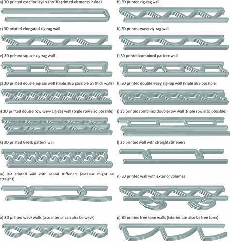
For example, the envelope and internal partitions of the six 1-story houses of the Community First Village in Texas were constructed with 3D printed walls with no cavities (Huang et al., Citation2022; Nielsen, Citation2020). Also, the first 3D residential building in Germany has single-layer 3D printed walls (Weger et al., Citation2022). However, the most typical designs for 3D printed concrete walls are with an air cavity or with multiple cavities defined by 3D printed elements between interior and exterior layers. Researchers in China studied four 3D printed concrete cavity wall patterns: cellular (hexagons), lattice (squares), triangles, and truss (Wang et al., Citation2020). Also, Suntharalingam et al. presented 3D printed concrete cavity walls with eight different cross-sectional arrangements (Suntharalingam, Upasiri et al., Citation2021). Figure shows a 3D printed concrete walls classification developed by the authors based on the patterns found in the literature.
Figure 1. 3D Printed Concrete Walls Classification based on their patterns. The classification also applies to slanted, curved, and organic shape walls. (Source: classification and figures by the authors)
The materials characteristics, the sizes of the aggregates, and the mixture design impact the extrudability and buildability of the 3D printed concrete (Tay, Y. W. D., Panda, B. N., Ting, G. H. A., Ahamed, N. M. N., Tan, M. J. & Chua, C. K, Citation2019). Also, the mechanical and thermal properties of the concrete mixtures vary depending on the materials utilized and their proportions. For instance, the density of the 3D printed concrete mixtures found in the literature varies from lightweight to normal-weight, ranging from 986 to 2,400 kg/m3, as Table shows. Studying 3D printed concrete mixtures properties, researchers from Stellenbosch University found that the extruded concrete has 0.9% less entrapped air than the casted concrete. With identical mixtures, the air content and density of the extruded mixture were 5.1% and 2,084 kg/m3, versus 6% and 2,061 kg/m3 of the casted mixture (Cicione et al., Citation2021).
Table 1. Examples of densities of 3D printed concrete mixture
Lightweight construction is gaining interest in the building industry. Therefore, several researchers are working on mixtures and extrusion systems that reduce the weight of the 3D printed concrete. Advances in that direction will benefit the construction industry with materials that are both strong and lightweight. The addition of lightweight components in the 3D concrete mixture can reduce its weight considerably (Alkhalidi & Hatuqay, Citation2020; Wang et al., Citation2020). Additionally, experimental studies show that with optimized 3D structures is possible to improve the strength-to-weight ratio by up to 50% (Tay, Y. W. D., Panda, B. N., Ting, G. H. A., Ahamed, N. M. N., Tan, M. J. & Chua, C. K, Citation2019).
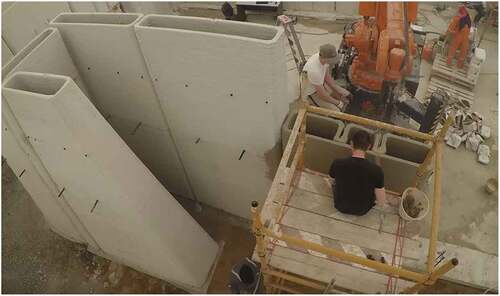
Large cavities are common in 3D printed concrete walls (Gosselin et al., Citation2016; Petter et al., Citation2010). Building professionals sometimes use these cavities to place or cast structural elements or fully or partially fill them with lightweight materials. However, in most cases, they just let them be unfilled, as in the example shown in Figure .
Figure 2. Examples of 3D printed concrete walls with large cavities. As per the classification in Figure , the walls in the photo correspond to “3D printed exterior layers” (at the left) and “3D printed wall with straight stiffeners” (at the right). (Source: Dubai Electricity and Water Authority©).
As in the hollow concrete blocks, the air cavities’ size and their arrangements affect the thermal performance of the 3D printed cavity walls due to the simultaneous effect of conductive, convective, and radiative heat transfer processes (Alkhalidi & Hatuqay, Citation2020). However, the cavities’ thermal performance can be enhanced by eliminating or reducing each heat transfer mechanism, individually or concurrently. In narrow cavities, the convective heat transfer is low since the movement of the air inside the cavity is restricted (Zhang & Yang, Citation2018). However, by incrementing the cavities’ dimensions, the air can move more freely, increasing the thermal transmittance. That means that the convective heat transfer acquires more relevance as the size of the cavity increases. Therefore, the author focuses their work on exploring the convective heat transfer in 3D printed cavity walls and evaluating a possible way to reduce it.
2.2. Convective heat transfer on wall cavities and hollow-core elements
The study of conjugate heat transfer through building envelopes is of paramount importance due to its influence on energy consumption and the occupants’ comfort. Cavity walls and hollow-core concrete elements are common building envelopes in many countries. In the absence of hollows or cavities, the conductive heat transfer is the essential aspect to consider for the analysis of the heat flux through the walls. However, in the presence of hollows and air cavities, the radiative and convective heat transfers have even more relevance
Several research works analyzed the radiative heat transfer in traditional cavities, and recently, some researchers have been working on the radiative heat transfer in 3D printed cavity walls. For example, Alkhalidi & Hatuqay utilized a Discrete Ordinate Radiation Model (DORM) to calculate the radiative heat transfer in the air cavities with different configurations (Alkhalidi & Hatuqay, Citation2020). However, as explained before and without diminishing the relevance of the radiative heat transfer, the focus of the present work is the study of the convective heat transfer on the 3D printed cavities and the assessment of a way to reduce it.
Regarding the convective heat transfer research, Elenbaas was one of the pioneers in experimental studies on natural convection. As part of his studies on vertical heated plates with fluid flows induced by buoyancy effects, he developed the correlations to estimate the Nusselt number (Elenbaas, Citation1942). After him, several researchers have studied the convective heat transfer and thermal performance of wall cavities, hollow masonry units, and glazing air spaces. Some of the relevant studies on this topic are summarized in Table .
Table 2. Thermal studies on wall cavities, hollow masonry units, and glazing air spaces
As can be seen from Table , there are several studies related to the thermal performance of the air cavities. However, the thickness and thermal fluxes on the cavities of the glazing and hollow masonry units are not the same as in the 3D printed concrete walls. Similarly, there are differences between the traditional cavity walls and the 3D-printed ones. In the last years, several researchers have been focusing their work on the thermal performance of the 3D printed cavity walls. Suntharalingam, Marais, and their colleagues are some of the researchers studying this topic (Marais et al., Citation2021; Suntharalingam, Upasiri et al., Citation2021). However, they also recognize that despite significant efforts by academics and industry in recent years, the use of 3D printed concrete is still challenging, and the current knowledge regarding its thermal performance is limited (Suntharalingam, Gatheeshgar et al., Citation2021). Some of the aspects that need more study related to the thermal performance of 3D printed concrete walls with air cavities are the convective heat transfer and the ways to minimize it. The literature points out that an effective mechanism in other construction elements is subdividing the air cavity into more and smaller ones. Thus, arises the question: Will subdividing the cavities also reduce the convective heat transfer in 3D printed concrete walls? Are the thermal benefits significant enough to justify the subdivisions?
3. Methods and materials
The current work is a revisited study on natural convection inside concrete cavity walls to contribute to the understating of the thermal behavior of 3D printed constructions and determining the effect on the thermal resistance of subdividing a square cavity into many smaller ones. To this end, the authors explored various cavity configurations and several Rayleigh numbers on flow regimes to assess air cavities’ thermal resistivity and heat losses using the COMSOL Multiphysics (V 5.5). First, the authors subdivided the studied cavity using solid elements of 1 mm thickness. Then, they carried out double simulations for each case, using the same number of divisions but with dividers with low and high conductivity. The following subsections describe the numerical model, the 3D printed wall’s boundary conditions, and the numerical solution and its validation.
3.1. Numerical model
The authors obtained the conjugative heat transfer through a 2D computational domain of cavity wall conducting steady-state finite element numerical simulations. The studied 3D printed wall section has a 220 mm x 220 mm cavity, as Figure shows. This construction element does not have complex geometry or discontinuous components, and neither has variations in its dimensions throughout its height and width. Therefore, the authors utilized a 2D thermal analysis. The formulation of the problem consists of 2D conduction heat transfer through the concrete segments of the wall plus natural convection in the air cavity. The motion of air due to buoyant force is limited within the impermeable boundaries of the cavity. The governing equation for conduction heat transfer through the concrete and cavity divider is,
And for natural convection inside the air cavities using Boussinesq approximation, governing equations are
Where p is pressure (Pa), ρ is the fluid density (kg/m3), the constant g denotes the gravitational acceleration, and “U” = (u,v) is the two-dimensional velocity vector (m/s) with u and v as velocity components in x and y directions. β is the coefficient of thermal expansion (for an ideal gas,, where T is the absolute temperature) and α is the thermal diffusivity. A buoyancy term was added to the right-hand side of the Navier-Stokes equation to account for the buoyant force. In this study, the laminar natural convection flow was modeled. The effects of radiation heat transfer inside the cavities were not considered. The computational domain (220 mm x 300 mm) is divided into more than 100,000 triangle elements, and the mesh was refined near walls where temperature gradients are significant. The Rayleigh non-dimensional number in the central cavity is around 2.2 × 10⁷. The Grashof number in natural convection plays the role of Reynolds number (Ra) in forced convection. Grashof number is a dimensionless number representing the buoyancy ratio to the viscous forces acting on the air. Rayleigh number is the product of the Grashof and Prandtl numbers, and the critical Rayleigh number for a vertical wall is 109. In turbulent regimes, the flow is strongly influenced by convection and buoyancy. The heat conduction gradually changes to natural convection in the cavity walls at Rayleigh numbers ≥ 105.
3.2. Boundary conditions and the properties of the materials
Figure shows the two-dimensional computational domain of the studied portion of the 3D printed cavity. The overall width of the studied wall section (300 mm) and the thickness of the 3D printed outer layers (40 mm) were the same in all the analyses. The wall temperature at the right and left sides of the computational domain are maintained at Tin = 21.85°C (295 K) and Tout = 41.85°C (315 K), respectively. Therefore, the temperature difference between outdoor and indoor temperatures is 20°C. The upper and lower wall boundaries were assumed as adiabatic. No-slip boundary conditions were applied to the walls inside the air cavity. Table presents the concrete and air properties assigned to the zones of the computational domain. The properties of the concrete utilized in this study match with normal weight concrete mixtures for 3D printed walls, see, Table (Lithium et al., Citation2019; Papachristoforou et al., Citation2019; Suntharalingam, Gatheeshgar et al., Citation2021). The air’s dynamic viscosity (µ) depends primarily on the temperature. For example, at standard atmosphere pressure, when the temperature is 25° C, its value is 1.849 × 10⁻⁵ kg/m-s, as Table shows. However, it increases to 1.918 × 10⁻⁵ kg/m-s when the temperature reaches 40° C. The study includes similar cavities with 4, 16, 64, 256, 1024, and 4096 subdivisions (Table ). As explained before, the subdivisions have 1 mm dividers with two different conductivities. In the first group of the double simulations, the material of the divider has low conductivity (k = 0.032 W/m.K), and in the second group, high conductivity (k = 0.27 W/m.K). The heat flux through the dividers in the lateral directions is negligible. The results and discussion section explains the constructive limitations of the 3D printed dividers on a 220 mm cavity and the maximum number of possible sub-cavities in that case.
Figure 3. Two-dimensional computational domain with concrete and air segments and boundary conditions.
Table 3. Properties of concrete mixture and the air
Table 4. Number of subdivisions of the original cavity and resulting sub-cavities sizes
3.3. Numerical solution and validation
The authors carried out a series of laminar conjugate convective steady-state simulations in a 2D computational domain. The numerical code was carefully validated against a standard benchmark solution in the literature, obtaining an excellent agreement for streamlines of Ra = 104, 105, and 106, with the Wakashima and Saitoh results, as shown in Figure (Wakashima & Saitoh, Citation2004). To better understand the convective transfer and the air movement in the cavity, the authors refined the calculation mesh in the zones near the 3D printed concrete walls where strong temperature gradients were expected. Additionally, they conducted independent mesh tests.
Figure 4. Comparison between the present numerical model temperature contours for Ra = 104, 105, and 106 in a square cavity at the first row and the benchmark solution (Wakashima & Saitoh, Citation2004) at the second row.
4. Results and discussions
The results and discussion are organized into two areas. The first includes the discussion about the effect of the increment of the cavity subdivisions on the heat flux of the analyzed section. Moreover, the second explains the impact of the Rayleigh number on flow regimes and the resulting heat fluxes.
4.1. Effect of the cavity subdivision
As was explained in the methodology section, the authors carried out double simulations to study the effect of the cavity subdivisions on the heat flux, with a difference of 20°C between the outdoor and indoor temperatures. Table presents de results of these simulations and the differences between them. The heat flux differences between dividers with low and high thermal conductivity are low until 16 subdivisions (less than 7%). The dividers’ thermal conductivity does not make a big difference in the cases with a few sub-cavities. However, the heat flux difference increases as the subdivisions increase. It is clear that the cases with high conductivity dividers have much higher heat flux in these situations.
Table 5. Normal heat flux in each of the studied cases
The dependence of heat flux across the air cavity is complicated due to the influence of heat transfer mechanisms. However, as Figure shows, there is a remarkable trend in the heat fluxes passing through the 3D printed concrete cavity wall. The heat flux in cases with low and high conductance dividers decreases linearly with the increasement of the subdivisions, from 2 to 64. Since too many subdivisions are impractical, these results support the statement that the heat flux will be lower as the number of subdivisions increases. The authors continued with additional simulations, increasing the number of the subdivisions to determine the limit of this trend, and they found that at some point between 64 to 256 subdivisions, increasing the number of subdivisions does not reduce the heat flux; contrary, increases it. At that point, the natural conductive heat transfer gets more relevance, and the heat transfer in the cases with high conductivity dividers is significantly higher than in the cases with low conductivity dividers. Also, the convection heat transfer is dominant in air cavities with a width larger than 25 mm. The heat flux passing through the cavity wall increases as the cavity width increases beyond 25 mm.
Figure 5. Normal heat flux vs. number of air cavities.
Figure also shows the normal heat flux of a solid concrete wall and the hypothetical case of a wall with one cavity filled with stagnant air. The heat flux in a solid 3D printed concrete wall, with the same width (0.30 m) and properties of the studied cases, is 120 W/m2, almost three times higher than the heat flux of the 3D printed wall with a large cavity. On the other hand, the hypothetical case of a wall with one cavity filled with stagnant air has a heat flux equal to 2.3 W/m2, seventy times lower than a wall with one cavity and non-stagnant air. In reality, the air in large cavities is not stagnant and circulates moved by the buoyant forces. In the conditions of the presented study, the heat flux through the 3D printed wall with one cavity and non-stagnant air reaches 40.4 W/m2.
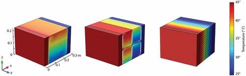
Figure shows the air velocity profiles and temperature on the analyzed cavity with 1, 4, 16, 64, and 256 subdivisions. Moreover, Figure presents a 3D projection of the cavity section temperature profiles with 1, 4, and 256 cavities. As shown in this figure, with the studied boundary conditions, the temperature in the cavity varies from 44.85° C to 24.85° C (298–318 K). The dividers break up the large air vortices into smaller ones, reducing heat flux through the 3D printed cavity wall, as Figures show. The heat fluxes linearly decline as the smaller cavities confine the air movements and convective heat fluxes. While the level of heat loss reduction is small, this trend is promising; however, it only continues till 256 cavities when cavity divider conductivity is 0.27 W/m.K. The heat flux bounced back by subdividing the cavity further to 256 using high conductive dividers. The reason is that the total surface area of the cavity is fixed, and as the number of cavities increases, the size of cavities gradually becomes comparable with the size of dividers (1 mm). Thus the normal conduction heat flux through the dividers increases the total heat fluxes for 1024 and 4096 cavities. For the case of the divider with a low conductivity of 0.032 W/mK, it can be seen that the heat losses came further down, and the stagnant air case is almost reached. However, the creation of these many air cavities is impractical. In this case, the heat flux does not bounce back, and further division of cavities does not increase the cavity wall’s total resistance remarkably. Instead, the sliced wall’s total thermal resistance becomes comparable to the large cavity with stagnant air when at least 256 or more air cavities are created in the wall. While these findings are significant, it is only numerically possible to reach such a thermal resistance level in a sliced cavity.
Figure 6. Air velocity profiles and temperature on the cavities with 1, 4, 16, 64, and 256 subdivisions.
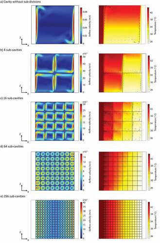
Figure 7. 3D projection of temperature profiles for cavities with no subdivisions and with 4 and 256 sub-cavities.
For a 220 mm x 220 mm section like the studied one, the maximum possible number of sub-cavities using 40 mm 3D printed dividers is 25. The size of these cavities will be 1.2 × 1.2 mm, and again the section will be dominated by the thermal properties of the dividers. Therefore, a better and more practical alternative would be to fill the cavity with insulating and porous materials (Suntharalingam, Upasiri et al., Citation2021). One may recognize the similarity between a network of numerous tiny cavities in this study, such as a porous medium of expanded polystyrene (EPS) beads, as the gaps among the beads are in order of a few millimeters. The application of EPS beads is not new, and retro-injected cavity wall insulation has been used, for example, in the UK since the 1970s. The EPS beads, consisting of 98% air, were injected into the walls’ cavity to enhance envelope thermal resistance. The bead filling in the cavity will remain an effective insulant for the building’s life and require no further maintenance (Davies, Citation2012; Gomaa et al., Citation2019; Mahmoud et al., Citation2012). The heat fluxes could be significantly reduced from the case of one large cavity by adding, for instance, a network of 64 cavities; however, the heat flux is still 200% higher than the stagnant air case. Due to the limitations found in the subdivision of patterns analyzed in this study to reduce the convective heat flow, in future works, we will study the effect of different subdivision patterns and compatible ways to fill 3D printed cavities. The latter has proven to be an effective way of minimizing or eliminating heat transfer in hollow clay bricks by up to 27.5% (Arici et al., Citation2016).
4.2. Effect of Rayleigh number
The authors investigated further their initial results through a non-dimensional conjugate heat transfer model and the effects of the Rayleigh number on temperature gradient profiles over the cavities subdivisions and presented them in this section.
A series of numerical simulations were conducted in laminar flow regimes to explore the dependency of air thermal resistivity on cavity size. These simulations are subject to similar boundary conditions, varying the Rayleigh number. The convection heat transfer is dependent on the Rayleigh number that is a function of the cavity critical length raised to the power of three ; thus, a small cavity has lower heat losses. Radiation heat transfer is not considered here. However, the radiation inside smaller cavities is also significantly reduced due to the presence of dividers (shields), as small cavity size is also associated with a small temperature differential across the cavity walls.
The temperature gradient profiles are plotted on a cut line perpendicular to the wall passing through the sliced cavities (typically, in the literature, temperature profiles are plotted; however, the temperature gradients reveal more information in this matter). In Figures , the findings are presented. For the case of four air cavities, three simulations were performed. For Ra = 104, there is no temperature gradient profile inside cavities, and air can act as an effective thermal barrier; however, as the Rayleigh number increases, significant temperature gradients alter the thermal resistivity of air. In other words, the four air cavity cases at high Rayleigh numbers cannot suppress the heat losses effectively. In another simulation, the Rayleigh number was fixed to 107, and the number of cavities was varied.
Figure 8. Non-dimensional temperature gradient inside the air space with four cavities for Ra = 104, 106, and 107.
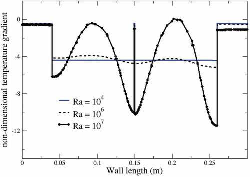
Figure 9. Non-dimensional temperature gradient inside the air space with 16 cavities for Ra = 107 and case of no flow, i.e., Nu = 1, temperature gradients still are significant.
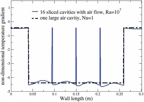
Figure 10. Non-dimensional temperature gradient inside the air space with 64 cavities for Ra = 107 and case of no flow, i.e., Nu = 1, temperature gradients are becoming less significant.
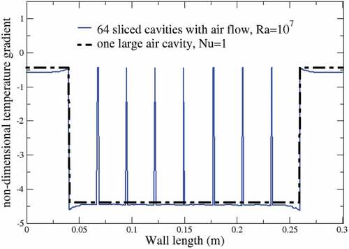
From the comparison between the case of 64 vs. 256 cavities in Figures , it is apparent that the 256 cavity case can confine air movement and flatten the temperature gradient profile, relatively similar to a cavity filled with stagnant air. In the case of 64 cavities, the temperature gradient is not flat and has a local maximum in the middle of cavities. Comparing the two cases shows the challenging task of keeping air motionless in 3D printed concrete cavity walls where the Rayleigh number is typically more than 105.
The study findings are also supported by the role of the heat transfer coefficient in air cavities. The non-dimensional Nusselt number for vertical walls is given by (Elenbaas, Citation1942). The correlations for Rayleigh number, Nusselt number, and heat transfer coefficient are
Variations of the heat transfer coefficient with cavity thickness (L) are shown in Figure . The conduction heat transfer mechanism dominates over convection heat transfer in the first 10 mm, as shown by the conduction Law of Fourier. In this range, as expected, the wall heat flux decreases significantly with the increasing cavity thickness due to the low conductivity of air (“h” is almost zero for small temperature differences inside tiny cavities). As the cavity thickness increases, convection heat transfer starts to show its effect, and the heat transfer coefficient increase linearly and rapidly. Both conduction and convection mechanisms compete in 5–20 mm. The decline in the conduction heat transfer -with the increasing width of the air cavity- is compensated with an increase in natural convection. Any cavity thickness increase beyond 25 mm, will further enhance the heat flux through the air cavity. With these findings and as evidenced in the literature, it is recommended that any air cavity beyond 25 mm should be filled with a light-weighted porous material to prevent air circulations in 3D concrete printed walls. Gomma et al. analysis also indicates that air cavities filled with straw significantly improve the 3D printed samples’ thermal resistivity relative to their density. Specifically, the air cavity filled with straw improved its thermal resistivity by 15% and its density by 8% (Gomaa et al., Citation2019).
Figure 11. Variation of heat transfer coefficient (h) with air cavity width between vertical plates.
5. Study limitations
There are several types of 3D-printed walls. However, the present study’s focus and findings are related to ones with large cavities and the convective heat transfer in these cavities. Other heat transfer ways, like radiative heat transfer, are not part of this study. The authors investigated the effect of the subdivisions on reducing the convective heat transfer. However, other relevant thermal-related subjects, such as the thermal mass, thermal bridge, time lag, and decrement factor, are not part of the scope of this study (Asan, Citation2000). We use the properties of a normal-weight concrete mixture for 3D printing constructions. Therefore, the obtained values might vary for the lightweight mixtures. However, the found trends also apply to other 3D printed concrete mixtures. Furthermore, this study does not address the structural or economic aspects of 3D concrete printed walls. Other heat transfer mechanisms and experimental verifications will be part of the authors’ future work.
6. Conclusions
This study aims to contribute to a research gap related to exploring the potential improvement of the thermal resistance of the unfilled cavities in 3D printed cavity walls, subdividing them into smaller ones. The authors carried out numerical simulations of conduction and convection heat transfer in a section of a 3D printed concrete cavity wall with various subdivisions. Contrary to previous studies, the present investigation shows the limitations and practical challenges of subdividing the large air cavities to reduce heat losses on the cavities of 3D concrete printed walls. The study reveals that:
The concrete partitions in actual construction can break up the large air vortices into smaller ones, partially reducing heat flux through the 3D printed cavity wall; however, the wall can be dominated by the thermal properties of the dividers as the number of dividers increases.
It is possible to reduce the heat flux of the studied cavity four times, from 40.4 W/m2 to 9.1 W/m2, subdividing it into sixteen small cavities. This reduction can be even more, increasing the number of subdivisions.
Subdividing the studied cavity into over 64 smaller cavities is unpractical, and indeed, the heat flux achieved with fewer subdivisions is comparable to that obtained with more subdivisions.
It is challenging to keep air motionless in air cavities of 3D printed concrete cavity walls where the Rayleigh number is typically more than 105 (where natural convection starts to become dominant)
For wide air cavities (more than 25 mm), other solutions than the subdivisions need to be explored to prevent air circulations inside the wall cavities.
Due to the limitations of the cavities’ subdivisions on the increase of thermal resistance, future research works shall focus on the integration of thermal insulation on the cavities of 3D concrete printed walls. In addition, future works will include low-weight concrete mixtures and the combined effect of radiative and convective heat transfer on the air cavities of 3D printed concrete walls.
Acknowledgements
The authors are grateful to Al Baheth’s capstone project fund from the Dubai Electricity and Water Authority (DEWA) R&D Center. They also appreciate the support from the Innovation and entrepreneurial incubator in HCT. AM would like to acknowledge the HCT interdisciplinary grant for generous financial support.
Disclosure statement
No potential conflict of interest was reported by the author(s).
Data availability statement
“Some or all data, models, or code that support the findings of this study are available from the corresponding author upon reasonable request.”
Additional information
Funding
References
- Ali, M. H., Issayev, G., Shehab, E., & Sarfraz, S. (2022, January). A critical review of 3D printing and digital manufacturing in construction engineering. Rapid Prototyping Journal, 28 (7), 1312–18. https://doi.org/10.1108/RPJ-07-2021-0160
- Alkhalidi, A., & Hatuqay, D. (2020). Energy efficient 3D printed buildings: Material and techniques selection worldwide study. Journal of Building Engineering, 30, 101286. https://doi.org/10.1016/j.jobe.2020.101286
- Antar, M. A., & Baig, H. (2009). Conjugate conduction-natural convection heat transfer in a hollow building block. Applied Thermal Engineering, 29(17–18), 3716–3720. https://doi.org/10.1016/j.applthermaleng.2009.04.033
- Arici, M., Karabay, H., & Kan, M. (2015). Flow and heat transfer in double, triple and quadruple pane windows. Energy and Buildings, 86, 394–402. https://doi.org/10.1016/j.enbuild.2014.10.043
- Arici, M., Yilmaz, B., & Karabay, H. (2016). Investigation of heat insulation performance of hollow clay bricks filled with perlite. Acta Physica Polonica A, 130(1), 266–268. https://doi.org/10.12693/APhysPolA.130.266
- Asan, H. (2000). Investigation of wall's optimum insulation position from maximum time lag and minimum decrement factor point of view. Energy and Buildings, 32(2), 197–203. https://doi.org/10.1016/S0378-7788(00)00044-X
- Bouchair, A., Tsai, K.-C., Chiang, Y.-K., Jiaang, W.-T., Wu, S.-H., Mahindroo, N., Chien, C.-H., Lee, S.-J., Chen, X., Chao, Y.-S., & Wu, S.-Y. (2008). Steady state theoretical model of fired clay hollow bricks for enhanced external wall thermal insulation. European Journal of Medicinal Chemistry, 43(8), 1603–1618. https://doi.org/10.1016/j.buildenv.2007.10.005
- Cho, S., Kruger, J., van Rooyen, A., & van Zijl, G. (2021, March). Rheology and application of buoyant foam concrete for digital fabrication. Composites Part B: Engineering, 215, 108800. https://doi.org/10.1016/j.compositesb.2021.108800
- Cicione, A., Kruger, J., Walls, R. S., & Van Zijl, G. (2021). An experimental study of the behavior of 3D printed concrete at elevated temperatures. Fire Safety Journal, 120, 103075. April 2020 https://doi.org/10.1016/j.firesaf.2020.103075
- Davies, T. (2012). Cavity walls—retro-injected insulation—kill or cure? Journal of Building Survey, Appraisal & Valuation, 1(4), 287–295.
- Elenbaas, W. (1942). Heat dissipation of parallel plates by free convection. Physica, 9.1(1), 1–28. https://doi.org/10.1016/S0031-8914(42)90053-3
- Gomaa, M., Carfrae, J., Goodhew, S., Jabi, W., Gomaa, M., Carfrae, J., Goodhew, S., & Jabi, W. (2019). Thermal performance exploration of 3D printed cob abstract. Architectural Science Review, 62(3), 230–237. https://doi.org/10.1080/00038628.2019.1606776
- Gosselin, C., Duballet, R., Roux, P., Gaudillière, N., Dirrenberger, J., & Morel, P. (2016). Large-scale 3D printing of ultra-high performance concrete – A new processing route for architects and builders. Materials & Design, 100, 102–109. https://doi.org/10.1016/j.matdes.2016.03.097
- Han, Y., Yang, Z., Ding, T., & Xiao, J. (2021). Environmental and economic assessment on 3D printed buildings with recycled concrete. Journal of Cleaner Production, 278, 123884. https://doi.org/10.1016/j.jclepro.2020.123884
- Henrique Dos Santos, G., Fogiatto, M. A., & Mendes, N. (2017). Numerical analysis of thermal transmittance of hollow concrete blocks. Journal of Building Physics, 41(1), 7–24. https://doi.org/10.1177/1744259117698522
- Huang, S., Xu, W., & Li, Y. (2022). The impacts of fabrication systems on 3D concrete printing building forms. Frontiers of Architectural Research, Xxxx, 11(4), 653–669. https://doi.org/10.1016/j.foar.2022.03.004
- Le, T. T., Austin, S. A., Lim, S., Buswell, R. A., Gibb, A. G. F., & Thorpe, T. (2012). Mix design and fresh properties for high-performance printing concrete. Materials and structures, 45(8), 1221–1232. https://doi.org/10.1617/s11527-012-9828-z
- Lithium, C., Pouch, I., Tests, P., Huang, M., Kong, L., Random, M., Memory, A., & Taniguchi, T. (2019). Thermal-humidity parameters of 3d printed wall thermal-humidity parameters of 3d printed wall. In IOP Conference Series: Materials Science and Engineering (Vol. 471, No. 8, p. 082018). IOP Publishing. https://doi.org/10.1088/1757-899X/471/8/082018
- Lorente, S., & Bejan, A. (2002). Combinedflow and strength'geometric optimization: Internal structure in a vertical insulating wall with air cavities and prescribed strength. International Journal of Heat and Mass Transfer, 45(16), 3313–3320. https://doi.org/10.1016/S0017-9310(02)00052-2
- Mahmoud, A. M., Ben-Nakhi, A., Alajmi, R. A. B.-N., & Alajmi, R. (2012). Conjugate conduction convection and radiation heat transfer through hollow autoclaved aerated concrete blocks. Journal of Building Performance Simulation, 5(4), 248–262. https://doi.org/10.1080/19401493.2011.565886
- Marais, H., Christen, H., Cho, S., De Villiers, W., & Van Zijl, G. (2021, March). Computational assessment of thermal performance of 3D printed concrete wall structures with cavities. Journal of Building Engineering, 41, 102431. https://doi.org/10.1016/j.jobe.2021.102431
- Nielsen, D. (2020). This 3D-printed village aims to house 40% of Austin’s homeless population. https://www.dwell.com/article/community-first-3d-printed-houses-icon-mobile-loaves-and-fishes-3f950815
- Papachristoforou, M., Mitsopoulos, V., & Stefanidou, M. (2019). Use of by-products for partial replacement of 3D printed concrete constituents; rheology, strength and shrinkage performance. 50(50), 526–536. https://doi.org/10.3221/IGF-ESIS.50.44
- Petter, B., Gustavsen, A., & Baetens, R. (2010). The path to the high performance thermal building insulation materials and solutions of tomorrow. Journal of building physics, 34(2), 99–123.
- Rodriguez-Ubinas, E., Montero, C., Porteros, M., Vega, S., Navarro, I., Castillo-Cagigal, M., Matallanas, E., & Gutiérrez, A. (2014). Passive design strategies and performance of net energy plus houses. Energy and Buildings, 83, 10–22. https://doi.org/10.1016/j.enbuild.2014.03.074
- Suntharalingam, T., Gatheeshgar, P., Upasiri, I., Poologanathan, K., Nagaratnam, B., Corradi, M., & Nuwanthika, D. (2021, June). Fire performance of innovative 3D printed concrete composite wall panels – A numerical study. Case Studies in Construction Materials, 15, e00586. https://doi.org/10.1016/j.cscm.2021.e00586
- Suntharalingam, T., Gatheeshgar, P., Upasiri, I., Poologanathan, K., Nagaratnam, B., Rajanayagam, H., & Navaratnam, S. (2021). Numerical study of fire and energy performance of innovative light-weight 3d printed concrete wall configurations in modular building system. Sustainability, 13(4), 2314. https://doi.org/10.3390/su13042314
- Suntharalingam, T., Upasiri, I., Gatheeshgar, P., Poologanathan, K., Nagaratnam, B., Santos, P., & Rajanayagam, H. (2021). Energy performance of 3d-printed concrete walls: A numerical study. Buildings, 11(10), 3–6. https://doi.org/10.3390/buildings11100432
- Tay, Y. W. D., Panda, B. N., Ting, G. H. A., Ahamed, N. M. N., Tan, M. J., & Chua, C. K. (2019). 3D printing for sustainable construction. Industry 4.0 - shaping the future of the digital world - proceedings of the 2nd international conference on sustainable smart manufacturing, S2M 2019, March 2021, 119–123. https://doi.org/10.1201/9780367823085-22
- Wakashima, S., & Saitoh, T. S. (2004). Benchmark solutions for natural convection in a cubic cavity using the high-order time – Space method. Journal of Heat and Mass Transfer, 47(4), 853–864. https://doi.org/10.1016/j.ijheatmasstransfer.2003.08.008
- Wang, L., Hailong, J., Zhijian, L., & Guowei, M. (2020). Mechanical behaviors of 3D printed lightweight concrete structure with hollow section. Archives of Civil and Mechanical Engineering, 20(1), 1–17. https://doi.org/10.1007/s43452-020-00017-1
- Weger, D., Gehlen, C., Korte, W., Meyer, F., Jennifer, B., & Stengel, T. (2022). Building rethought – 3D concrete printing in building practice. Construction Robotics, 5(3), 203–210. https://doi.org/10.1007/s41693-022-00064-5
- Xamán, J., Cisneros-carreño, J., Hernández-pérez, I., & Hernández-lópez, I. (2017). Thermal performance of a hollow block with/without insulating and reflective materials for roofing in Mexico. Journal of Applied Physiology (Bethesda, Md.: 1985), 123(1), 243–255. https://doi.org/10.1016/j.applthermaleng.2017.04.163
- Zhang, Y., & Wang, Q. (2017). Influence of hollow block’s structural configuration on the thermal characteristics of hollow block wall. Procedia Engineering, 205, 2341–2348. https://doi.org/10.1016/j.proeng.2017.10.306
- Zhang, T., & Yang, H. (2018). Optimal thickness determination of insulating air layers in building envelopes. Energy Procedia, 152, 444–449. https://doi.org/10.1016/j.egypro.2018.09.251