
 ?Mathematical formulae have been encoded as MathML and are displayed in this HTML version using MathJax in order to improve their display. Uncheck the box to turn MathJax off. This feature requires Javascript. Click on a formula to zoom.
Abstract
The harmonic drive (HD) is increasingly used due to its outstanding advantages, especially for equipment requiring high precision and a large gear ratio. This research is based on the Finite Element Method (FEM) and mechanical analysis to investigate stress calculation methods for the flexspline (FS), a significant component of HD transmission, providing a basis for assessing the durability and failure of the FS. First, the FS deformation and stress analysis model based on the FEM is proposed. Since the two boundary elements of the model have the form of a rotation and translational joint, which have not been provided, based on the stiffness matrix of the fixed beam to build the stiffness matrix for these elements, which completes the proposed analytical model. Then, the structures of an HD reduced are designed and applying the proposed force analysis model, the deformation and stress distributions of the FS are obtained. Finally, the theoretical safety factor is calculated and analyzed. The results of the simulation completely coincide with the theoretical calculation and show that the most concentrated stress is at the root of the teeth, which is the leading cause of the FS failure. So, the study as reference material for rapidly evaluating the stress state and calculating the safety when designing and optimizing the FS.
PUBLIC INTEREST STATEMENT
This research is based on the Finite Element Method (FEM) and mechanical analysis to investigate stress calculation methods for the flexspline (FS), a significant component of HD transmission, providing a valuable method for assessing the durability and failure of the FS. First, the FS deformation and stress analysis model based on the FEM is proposed. Then, the structures of an HD reduced are designed, and applying the proposed force analysis model, the deformation and stress distributions of the FS are obtained. Finally, the theoretical safety factor is calculated and analyzed. The simulation results coincide with the theoretical calculation and show that the most concentrated stress is at the root of the teeth, which is the leading cause of FS failure. So, the study, such as reference material for rapidly evaluating the stress state and calculating the safety when designing and optimizing the FS.
1. Introduction
Harmonic drives (HD) have the advantages of being lightweight and having a high transmission ratio and are widely used in precision transmission fields such as medical equipment, aerospace, and robotics (Brassitos & Jalili, Citation2017; Shen & Ye, Citation1985; Shuyan Wang et al., Citation2021; Ueura & Slatter, Citation1999). HD transmission uses elastic deformation formed in a flexible part called the flexspline (FS) to perform motion or power transmission (Yu et al., Citation2021). As an essential component of HD transmission, the FS is an elastic thin-walled structure and operates under alternating loads. As a result, fatigue failure of FS is one of the most common types of failure (Ma et al., Citation2017; Shi et al., Citation2010; Wang & Chen, Citation2005; Y.F. Wang et al., Citation2005). Therefore, studying the deformation and stress distribution of the FS is the basis for evaluating the FS’s safety, durability, and fatigue failure during the HD gear’s dynamic working process (Sahoo et al., Citation2020).
The experimental method is commonly used for stress testing of HD (Li, Citation2016; Pacana et al., Citation2017; Tjahjowidodo et al., Citation2013). Sticking strain gauges on the FS’s surface can measure stress (Guan et al., Citation2022; İrsel, Citation2021). However, strain gauges cannot obtain stress on teeth because of their narrow space with this approach. Furthermore, the experimental method is hard because of the extended test cycle and high cost (J. Wang et al., Citation2021). In addition, the deformation and stress distribution of FS is also determined by the empirical formula. M.H. Ivanov (Ivanov, Citation1987) and Shen et al. (Shen & Ye, Citation1985) provide a computational model using the column shell theory based on elastic theory and some additional assumptions for the model based on experimental results. In recent years, many works have been based on FEM to obtain a more accurate deformation and stress distribution of the FS (Cheng & Chen, Citation2022). Kayabasiet and F. Erzincan conducted a stress-strain analysis of the FS based on FEM to calculate the stress on the teeth of the FS and found the optimal tooth geometry to maximize the duration of the FS’s life (Kayabasi & Erzincan, Citation2005). Through finite element contact analysis, S.M. Zhang determines the boundary conditions and the initial load by surface contact between FS and the wave generator (WG; Zhang, Citation2009). The deformation and stress can be collected under different conditions, providing valuable data for optimizing the structures of the FS. Chen et al. based on the shell element and distribution of deformation in the transmission state obtained by nonlinear contact analysis set up an FS finite element model (Chen et al., Citation2011). Zou et al. established a surface contact finite element model of an HD through which they found that strain and stress in the cross-section of the FS gear changed geometry with high loads, even though the distribution of the increments in deformation and stress did not change (Zou et al., Citation2013). However, the above analysis cannot meet the structure’s integrity requirements because of the high reliability, safety, and long life.
Furthermore, technically FEM depends on computers and commercial software; modeling and preprocessing FEM is time-consuming to process and obtain results (S. Wang et al., Citation2019). Engineers needed a fast and reliable stress calculation method to evaluate the stress and safety of the FS. Therefore, a quick procedure with precise accuracy and reliability is practical for engineering.
This paper investigates the mechanical analysis methods (MAM) and rapid stress calculation for FS. The disadvantage of the original form is that it does not consider the FS ring length, so propose a new rapid method based on MAM and FEM, which is very helpful in computing the FS’s stress. After that, the finite element model for each factor is established; building each type of matrix in the proposed model is guided in detail. Next, a complete FS design is designed and manufactured, and through the proposed mathematical model, the deformation and stress of the FS have been obtained. Finally, the factor of safety of FS is also calculated, analyzed, and compared with the simulation results.
2. FEM model calculates flexspline stress
2.1. The basis of the method applied to the FS
The FEM divides the continuous geometric model into discrete elements and replaces them with displacement functions. The properties of the mechanical system, including the node displacement, the node force, and the stiffness, are described in a system of algebraic equations as follows:
where:
is the stiffness matrix (SM) of the element system;
is the displacement matrix of all nodes in the model;
is the node force matrix of all nodes in the model.
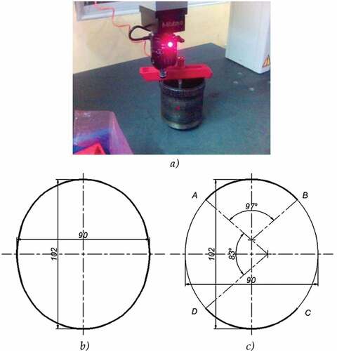
In the loaded state, the stress falls mainly at the root of the FS, since that is where the material concentration is the lowest relative to other points. Assume the law of the external force acting on the FS, as shown in Figure ). It is possible to consider an element distributed over one tooth, ignoring the difference of the force distributed at both ends, to see that each element is a uniformly distributed force. There is a jump of the distributed force at the node between two elements (Figure )).
Figure 1. FEM model calculates FS stress.
Experiments with isotropic materials have shown that the dark bands (representing deformation) are also concentrated mainly on the gear’s root. The FS has a number of teeth over 90 in the assembled state with a WG whose deformation does not exceed 1/5 of the tooth height (Ginz Bun, Citation1966; Seit Lin & Sukermam, Citation1972). Furthermore, these deformations are only within the root clearance, not affecting the engagement process. In the worst case, the deformation on the teeth does not exceed 1/3 of the teeth height, and this strain height decreases as the number of FS’s teeth increases. The FS’s profile change when working is described as shown in Figure . The FS’s deformation in the direction of deformation caused by the WG is up to 2.m in magnitude, where m is the modulus of the FS that does not affect the change in the tooth’s original shape in the working area.
Figure 2. The change of the FS’s profile when working.
With the parameters of the material’s mechanical properties and the geometric relationship of the elements on the FS after deformation, there is enough basis for building the stiffness matrix of the element system. After determining the geometry of the FS’s neutral curve, based on the assumption of the above distribution of elements, the displacement matrix of the element system can be determined compared to before being affected by force.
Therefore, the “initial preliminary” solving process is completed after calculating the node force from EquationEquation (1)(1)
(1) . After that, there is enough data to solve the forward force problem for the displacement and stress of the mechanical system. The FEM software will solve the problem with the input data of the node force calculated from the above problem. Then the safety coefficient will confirm the functional ability of the FS. The following introduces the basis for determining the quantities present in EquationEquation (1)
(1)
(1) .
2.1.1. Establish the stiffness matrix of the element system
Recommend model
The FS shape often has two symmetry axes (over two symmetry axes are rarely used, so it is not considered). How to model general and show the relationship between the rest is a problem that needs to be solved. The following model is suggested for consideration:
The FS has only vertical and horizontal displacements when mounted on a WG. Therefore, the model’s first and last two elements must represent the connection with the rest of the FS. They are represented as a rotation and translational joint, with the translation direction coincident with the direction of the symmetry axis (Figure ). This generates a link backlash at the node with the removed part. All remaining elements are represented as rotation joints. Because these rotation joints are in space, so each node has three displacements: vertical, horizontal, and angular.
Figure 3. FS node force model.
The elements in the kinematic series, apart from the angle in the standard frame of reference, are different. However, the mechanical and physical parameters, such as EF, EJ, and length L, are the same. Furthermore, the node-numbered elements continuously increase in one direction. Therefore, the calculated stiffness matrix is a band matrix (Table ). These observations make the data entry process less time-consuming.
Table 1. The stiffness matrix is obtained by adding the extended matrices
The local reference and global reference systems
With the parameters of the material’s mechanical properties and the geometric relationship of the elements on the FS after deformation, there is enough basis for building the stiffness matrix of the element system. After determining the geometry of the FS’s neutral curve, based on the assumption of the above distribution of elements, the displacement matrix of the element system can be determined compared to before being affected by force.
In Figure ), the elements are denoted respectively, in the anti-clockwise direction. Since the pitch on the neutral curve is constant, naturally, the elements formed based on this curve have the same length, the common symbol is
.
Choose z local reference system according to the right-hand rule, the origin of the reference system is from to
as specified, which is located at the node with the smaller index of the element under consideration. The positive direction of the Ox axis is always from the small node to the large node of the element. The Oy axis is self-determining positive in the direction of positive rotation around Oz of the system. The global reference system of the chosen system coincides with the reference system with the smallest index of the local reference systems mentioned above.
There are two ways to convert the reference systems to each other: the direction cosine of the elements or the rotation matrix. We can choose the second way for convenience because the transpose components in the displacement matrix will be present more fully.
According to Figure ), the angle between two consecutive elements is equal to that of two consecutive teeth in the distribution curve.
where is not the FS’s number of teeth, but the gear’s number of teeth that has a module equivalent to the FS, and the radius equal to the radius of the oval equivalent to the arc in consideration. (In the case of using a driving disc, the contact angle is as large as
, so this arc is naturally controlled by the driving disc and has the form of a circular arc, whose radius is derived from the radius of the driving disc).
The major arc radius of the oval must be calculated from smooth transition conditions and conditions such as the eccentricity of the two driving discs (details of the calculation are presented in Section 3.2).
The relationship of the stiffness matrices in the global and local reference system is built (Tinh, Citation1999):
Determine the mechanical properties of the elements such as: l, EF, EJ
Determine the SM of the elements in the local reference system
The form of the SM of the bar element with two rotating ends in the local reference system can be found in the reference (Tinh, Citation1999). Unlike the elements on the inside, two elements on the model’s boundary have the form of a link as a rotation and translation joint. However, the stiffness matrix form of the bar with a connection like this is not provided. Hence, it is necessary to base on the fixed beam’s stiffness matrix form to build the bar’s stiffness matrix with a rotation and translational joint.
Consider a bar with a minor node (symbol i) connecting a rotation joint and a major node (symbol j) connecting a translational joint, as shown in Figure . The relationship between the internal forces of the two nodes and the displacements of the fixed beam is given by the following system of equations:
Figure 4. Bar with a rotation joint and a translation joint.
At the minor node i, bending moment , shear force
, assign these values to the Equationequations (4)
(4)
(4) and derive the corresponding quantities
replacing all the remaining positions in the system. We have the relationship between the internal force and the displacement of the minor and major nodes. Then, converting the relationship to the formation matrix, the stiffness matrix obtained is as follows:
Do the same for the bar with a major node connection, the result is the same. So, it can be seen that this is also the SM form of the bar with two ends of the rotation and the translational joint. The stiffness matrix of all elements present in the model is the same, so it is very convenient for calculations because these are sparse matrices and most coefficients are zero.
2.1.2. Establish the displacement matrix of the element system
Building displacement matrix will be the basis for calculating the intensity of the external force applied to each segment of the FS. The displacement determination is based on the measured data directly on the FS after putting it into a working state.
Figure shows how to determine the displacement matrix of an FS with Z = 98, m = 1 (design details are presented in Section 3.1)
Figure 5. The process of building the displacement matrix of the element system.
Choose a reference system that does not coincide with the first element of the system, following the right-hand rule with an axis, as shown in Figure . Since the FS has two axes of symmetry, only 1/4 of the FS ring is considered, which reduces the size of the stiffness matrix. As shown in Figure ), after determining the model with only a quarter of FS teeth, the elements are defined as connecting nodes as shown in Figure ) by identical circles. The pre-deformation state divide command allows evenly dividing of the gear ring, replacing curved arcs with straight segments so that angular displacement can be measured, as shown in Figure ). The displacement matrix shown here includes the signs of the quantities according to the standard frame of reference. The length displacement dimension is mm, and the dimension of the angular displacement is decimal degrees, measured with four zeros after the decimal point.
2.1.3. The reasonableness of the proposed model
With external gears, it is possible to experience tooth break due to load. However, with wave drive, the number of teeth in simultaneous engagement is much larger, and the total bending area of all teeth engaged at a time is much larger than the bearing area in a tooth groove.
Statistical practice shows that the major form of FS failure occurs at the root of the tooth, more precisely, the metal cup in which the teeth are distributed.
Because the modulus of transmission determines the thin wall thickness, a strong enough tooth cup is necessary and sufficient to ensure that the modulus has been appropriately chosen.
The computational model can be expanded if it is desired to add different force components to the model. For example, the modeling of the transmission of force on the teeth reduced to the root, which is represented by the EquationEquation (6)(6)
(6) node force matrix:
3. Cases study and analysis
3.1. FS and CS geometry design
A practical case is design to illustrate the method:
The HD reduction ratio is 50, the module m = 1 and having the involute tooth profile. The main geometric design parameters are as follows:
Dual wave drive:
Thin wall thickness coefficient:
FS profile shift coefficient:
Transmitter conversion module:
The radius of the neutral circle of the FS
The diameter of the pitch circle of the FS
=ZF.m = 98.1 = 98(mm)
The radius of the end curve of the FS neutral curve :
The radius of the addendum of the FS :
Correspondingly with above the FS, the geometric parameters of circular spline (CS) are as follows:
The diameter of the pitch circle of the CS
The radius of the addendum of the CS
The diameter of the dedendum of the CS
The above geometric parameters allow us to determine the basic geometrical parameters of the FS and CS. If machining using the envelope contour method, there is no need to determine more specific factors about the tooth profile. Suppose machining on an EDM requires a detailed drawing of the tooth profile as input for the tool path on the machine. Table shows that Autolist programming allows for defining the detailed drawing of the above tooth profile:
Table 2. Programmatically determine the detailed drawing of the tooth profile
A complete tooth profile is obtained after running the program from the Auto-CAD environment. Then, based on the above-calculated parameters, complete the drawing of the FS and CS as shown in Figure .
Figure 6. Completed FS and CS design drawing.
3.1.1. Application of the proposed method to calculate stress for FS
This section shows how to calculate the stress acting on FS with the number of teeth Z = 98 and the module m = 1 as in the design above.
Using the EDM method to machine the FS, after mounting the FS with the WG, the shape of the neutral curve can be determined using a three-dimensional coordinate measuring machine (CMM), as shown in Figure ). The measured sample result has two semi-major axes and two semi-minor axes of oval shape, Figure ).
Figure 7. The design, model, and neutral curve measurement results of the FS.
When taking the semi-axes of the FS to construct the oval instead, the list command of AutoCAD gives us the circumference of the scanned image as 302,7204(mm), giving the circumference of the oval shape as 301,9934(mm), so the oval equivalent is acceptable (Figure )). The list command for the circumference of arc AB of the oval is 70,1180(mm), and for the circumference of the arc, BC is 80,8787(mm). Because they are all arcs, so the teeth of the FS on each arc will be evenly distributed around its center, based on the relation of corresponding sides perpendicular.
The angle between two consecutive teeth (two elements) on the AB arc is:
Taking an element through three teeth because of the small gear modulus, the rotation angle of the three teeth is relatively significant. Therefore, the tooth pitch here is three times the actual tooth pitch, with the modulus m = 1 of the FS.
Similarly, the angle between two consecutive teeth (two elements) on the AD arc is:
Particularly for the first element, having the x-axis created with the Ox axis of the global reference system angle, the following rotation matrix should be used:
For the second element, the rotation angle is , the corresponding rotation matrix is:
On that principle, the subsequent rotation matrices need to add the angle .
From the fifth element onward, the rotation angle needs to be added
Determine the mechanical properties of the elements: The FS designed is made of 40XC material and has the following properties:
Steel FS with the module of elasticity:
Cross-sectional area:
Based on the drawing, the Massprop command gives us: ;
;
After substituting numbers according to the mechanical properties specified above, all elements of the system have the form of a stiffness matrix associated with the local reference system as follows:
The SM of the element system is built based on this matrix, and the rotation matrices from R1 to R8 mentioned above is a matrix of size 24*24 obtained by adding the elements. The construction of the SM of the element system is completed.
Determine the matrix of displacement as presented in Section 2.3. The result is shown in Figure ).
Substituting the displacement matrix and the stiffness matrix into the EquationEquation (1)
(1)
(1) , we get the node stress to result as follows:
(16,0764; 1,9598; 0; 57,7732; 24,9346; 0; 4,6034; 23,6091; 0; 85,8433; 119,3588; 0; −123,8549; 34,4285; 0; −72,3440; −58,2948; 0; −43,3082; −58,2622; 0; −23,3412; −87,7338; 0; 0; 0; 0)^T
3.1.2. Calculation and simulation to check the safety factor of the FS
As analyzed in Section 2.1, the safety coefficient will confirm the functional ability of the FS. Therefore, this section will calculate and simulate the functional ability of FS based on the above stress analysis results to verify the proposed method results.
The FS ring is part of working under heavy conditions, so its safety factor must be greater than 1,5. The following are the two main test procedures corresponding to the results of the geometrical and mechanical parameters of the above FS design.
Check according to the traditional model
Specifically, the data of the FS designed above is made of 40XC material, FS is the active link. Incorporation of the FS geometry data when calculating kinematics:
Determine the minimum normal stress acting on the wall of the suture on the tooth distribution segment:
The value determined according to the graph is 2,75.
The value of torsional stress on the wall of the FS in the limited groove portion of the toothed section is calculated as follows:
The frequency and cyclic stress are calculated:
With 40XC crafting materials there are .
The following formula determines the factor of safety under normal stress.
Therefore, the combined factor of safety will be:
This safety factor is more significant than 1,5 to satisfy the requirements of working durability; the calculation is finished.
Test with Cosmos Design Star simulation software
To perform the test, build a 3D model of the FS on AutoCAD Mechanical Desktop. Export files as (*.iges) or (*.igs). Import the model into the Cosmos Design Star environment, and do the following:
- Determine the material’s mark through the physical and mechanical parameters of the material.
- Set force based on the result of the node stress
- Control the displacement while working.
- Discrete continuous model of FEM model.
- Run interactive solver program.
- Select the test standard.
- Evaluation of result.
The software allows checking the factor of safety according to three basic criteria:
Mohr—Coulomb stress: FOS = 4,4
Test formula:
Maximum Von Mises stress: FOS = 4,4
Test formula:
Maximum shear stress (Tresca): FOS = 4,4
Test formula:
Figure shows the FS simulation results, specific deformation and stress contour plots.
Figure 8. Computational simulation results on cosmos design star
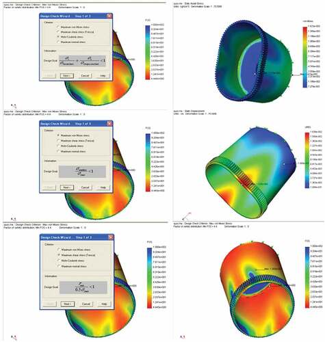
In Figure , the stress distribution of FS perfectly agrees with the proposed mathematical model. The deformation causing the internal bending moment has been discussed in Section 2, which is used to compute the stress via the MAM. According to the simulation results, the most significant stress occurs at the tooth root on the central axis of WG, which is also wholly consistent with many current research results and utterly correct according to the initial assessment of the research team. Soon, to further demonstrate the feasibility of the novel method, the research team will increase the number of fabricated teeth of FS to study the relationship between stress reduction and deformation at the tooth root.
The test results for the stress safety factor are all 4,4 quite close to the results calculated by theory 4,279. It shows that the proposed method helps quickly calculate the FS’s stresses. Therefore, engineers have one more reference method for stress assessment of FS during harmonic actuators’ design and structural optimization.
4. Conclusions
In this research, the stress computation methods for FS have been analyzed, a harmonic reducer was designed and manufactured, and the stress in FS was analyzed according to the proposed method. Some primary conclusions can be drawn as follows:
- The usual MAM can’t fully express the influence of the material’s stiffness and the FS’s displacement on stress. Therefore, a quick method based on the FEM model was proposed. The method obtained the analytical relationship between FS’s stiffness, deformation, and stress.
- Building a computational model of the stiffness matrix for the bar element at the border has connecting rotation and translational joints. Establish a complete model and a stress calculation process for the entire FS.
- The stress and safety factors of FS have been solved in the proposed model, and the simulation results are entirely consistent with the theoretical analysis results, which is approximately 4,4 almost three times greater than the standard safety factor of 1,5. The simulation results also show that the stress is most concentrated in the tooth root, which is the leading cause of fatigue failure of the FS. Furthermore, the experiment’s results on the actual FS set verified that the quick stress computation method can reach accurate results.
Disclosure statement
No potential conflict of interest was reported by the author(s).
Additional information
Funding
Notes on contributors

ThanhTrung Trang
ThanhTrung Trang (1983, Male), PhD. He received a B.S and M.S in Mechanical Engineering from the Faculty of Mechanical Engineering, Thai Nguyen University of Technology, Vietnam in 2006 and 2011, respectively. In 2018, He received a Ph.D. degree in mechanical engineering from the Mechanical and Automotive Engineering, South China University of Technology, China. From 2018 to 2022, he was a Postdoctoral Researcher at the School of Automation Science and Engineering, South China University of Technology. His research interest covers mechatronics, robotics, automation in manufacturing, and optimization methods. He has published more than 18 international academic papers and is the main responsible for three research topics at the provincial and national levels in China.
References
- Brassitos, E., & Jalili, N. (2017). Design and development of a compact high-torque robotic actuator for space mechanisms. Journal of Mechanisms and Robotics, 9(6), 061002. https://doi.org/10.1115/1.4037567
- Cheng, Y.-H., & Chen, Y.-C. A general mathematical modeling and finite element analysis of a strain wave gear possessing a double-circular-arc-with-a-common-tangent profile. Proceedings of the institution of mechanical engineers, part c: journal of mechanical engineering science 2022
- Chen, X. X., Lin, S. Z., Xing, J. Z., & Liu, Y. S. (2011). Deformation of harmonic drive in transmission state based on contact analysis with shell element tooth. Applied Mechanics and Materials, 86, 771–18. https://doi.org/10.4028/www.scientific.net/AMM.86.771
- Ginz Bun, E. G. 1966. Wave gear transmission Russian version. Machine Building Publishing House.
- Guan, J., Zhou, X., Liu, L., Ran, M., & Yan, Y. (2022). Investigation of tri-axial stress sensing and measuring technology for tire-pavement contact surface. Coatings, 12(4), 491. https://doi.org/10.3390/coatings12040491
- İrsel, G. (2021). Research on electrical strain gages and experimental stress analysis: Case study for a full wheatstone bridge. DUJE (Dicle University Journal of Engineering), 12(5), 783–792. https://doi.org/10.24012/dumf.1051434
- Ivanov, M. H. 1987. The harmonic drive In Chinese. National Defense Industry Press.
- Kayabasi, O., & Erzincan, F. (2005). Shape optimization of tooth profile of a flexspline for a harmonic drive by finite element modeling. Materials and Design, 28(2), 441–447. https://doi.org/10.1016/j.matdes.2005.09.009
- Li, S. (2016). Diaphragm stress analysis and fatigue strength evaluation of the flexspline, a very thin-walled spur gear used in the strain wave gearing. Mechanism and Machine Theory, 104, 1–16. https://doi.org/10.1016/j.mechmachtheory.2016.05.020
- Ma, D. H., Wu, J., Liu, T., & Yan, S. (2017). Deformation analysis of the flexspline of harmonic drive gears considering the driving speed effect using laser sensors. Science China Technological Sciences, 60(8), 1175–1187. https://doi.org/10.1007/s11431-016-9060-y
- Pacana, J., Witkowski, W., & Mucha, J. (2017). FEM analysis of stress distribution in the hermetic harmonic drive flexspline. Strength of Materials, 49(3), 388–398. https://doi.org/10.1007/s11223-017-9879-z
- Sahoo, V., Mahanto, B. S., & Maiti, R. (2020). Stresses in flex gear of a novel harmonic drive with and without pay load. Aust J Mech Eng, 1–15. https://doi.org/10.1080/14484846.2020.1769462
- Seit Lin, N. I., & Sukermam, E. M. 1972. Wave gear transmission Russian version. VINITI Publishing House.
- Shen, Y. W., & Ye, Q. T. (1985). Theory and design of harmonic drive gearing. China Machine Press.
- Shi, W., Zhang, Q., & Li, X. (2010). The research about deformation and stress of flexspline in harmonic drive based on ABAQUS. Mechanical Engineer, 6(In Chinese), 44–47. https://kns.cnki.net/kcms/detail/detail.aspx?dbcode=CJFD&dbname=CJFD2010&filename=JXGU201006033&uniplatform=NZKPT&v=RXBzoVCa9rrQLB0ys33M5b_RtnXjSn3F57F8dk5A_EfPhoTZzf74W6KaQlSilp8w
- Tinh, D. (1999). Finite element method for calculating frame and foundation works simultaneously with the foundation. Vietnamese version. Science and Technology Publishing House, Hanoi.
- Tjahjowidodo, T., Al-Bender, F., & Brussel, H. V. (2013). Theoretical modelling and experimental identification of nonlinear torsional behavior in harmonic drives. Mechatronics, 23(5), 497–504. https://doi.org/10.1016/j.mechatronics.2013.04.002
- Ueura, K., & Slatter, R. Space Mechanisms and Tribology. Proceedings of the 8th European symposium european space agency, Toulouse, France, 1999, 438:259–264.
- Wang, Y., & Chen, Y. (2022). Experimental study on the influence of flexible bearing clearance on natural frequency of harmonic reducer. Journal of Advanced Mechanical Design, Systems, and Manufacturing, 16(1), JAMDSM0012–JAMDSM0012. https://doi.org/10.1299/jamdsm.2022jamdsm0012
- Wang, S., Dongliang, L., Mao, S., & Chen, B. (2021). Design and analysis of cam wave generator based on free deformation in non-working area of the flexspline. Appl. Sci, 11(13), 6049. https://doi.org/10.3390/app11136049
- Wang, S., Jiang, G., Mei, X., Zou, C., Zhang, X., & Zhang, H. (2019). A rapid stress calculation method for short flexspline harmonic drive. Engineering Computations, 36(6), 1852–1867. https://doi.org/10.1108/EC-08-2018-0364
- Wang, Y. F., Li, S. G., & Xie, T. (2005). Finite element mechanics analysis of flexspline in harmonic driver and improvement of structural parameter. Optics and Precision Engineering, 13(In Chinese), 86–90. https://kns.cnki.net/kcms/detail/detail.aspx?dbcode=CJFD&dbname=CJFD2005&filename=GXJM2005S1018&uniplatform=NZKPT&v=FpPsFoeQ-cdswskYGzuWrhqhZx8vKp5ow7phcL8u9s4MLqX8AMP43ZFSx7o80g-n
- Wang, J., Wan, Z., Dong, Z., & Li, Z. (2021). Research on performance test system of space harmonic reducer in high vacuum and low temperature environment. Machines, 9(1), 1. https://doi.org/10.3390/machines9010001
- Yu, Z., Ling, S., Wang, X., & Wang, L. (2021). Study on tooth profile design of harmonic drive with deformation model of flexspline. Meccanica, 56(7), 1883–1904. https://doi.org/10.1007/s11012-021-01372-w
- Zhang, S. M. (2009). Stress analysis of flexspline in harmonic gear drive based on ANSYS, master dissertation. Shanghai Jiao Tong University. In Chinese.
- Zou, C., T.t, G. D. J., & Mei, X. S Deformation and stress analysis of short flexspline in the harmonic drive system with load. IEEE International Conference on mechatronics and automation 2013, 676–680.