
 ?Mathematical formulae have been encoded as MathML and are displayed in this HTML version using MathJax in order to improve their display. Uncheck the box to turn MathJax off. This feature requires Javascript. Click on a formula to zoom.
Abstract
Because a variety of fuels can be burned during the combustion process, CFB boilers have a very wide range of applications in coal-fired power plants. The uneven distribution of homogeneity between the air and the particles and the large volume fraction in some locations could result in erosion of the furnace walls. In order to decrease the impacts of erosion, the ring baffle feature is added to the furnace wall. In order to compare data variations in the form of ring baffle depth with variations of 0.15 m, 0.3 m, and 0.45 m as well as the number of ring baffles 1 and 2, the CFD approach is utilized. The factors tested included pressure drop distribution, particle volume fraction distribution, particle axial and radial velocity distribution, and shear stress. With a maximum value of 0.012 for the volume percent, the variation of two ring baffles with a depth of 0.3 m each offered the best results in terms of homogeneity inside the CFB of the boiler. Additionally, a pressure decrease of 7.38 kPa was seen due to the maximum axial and radial speeds that were measured at the ring baffle, which were 27.1 m/s and 2.46 m/s, respectively. Additionally, the furnace wall can avoid probable erosion thanks to the shear stress contours, which mirror the volume percentage of particles.
1. Introduction
Using Circulating Fluidized Bed (CFB) boilers has advantages over other boiler types. The range of its uses allows for the production of power, pharmaceuticals, and food drying (Li, Zhang, Jiang, Wang, et al., Citation2020; Li, Zhang, Jiang, Wang, et al., Citation2020; Wang et al., Citation2014). CFB boilers are dependable due to the choice of flexible fuel materials, low NOx gas emissions, and resistance to extreme loading conditions (Basu, Citation2015; Gu et al., Citation2020; Liu et al., Citation2017; Wanchan et al., Citation2020; Wu et al., Citation2018; Xu et al., Citation2016; Zhang et al., Citation2010). As a result, research has been done on the flow, combustion, and displacement behavior of CFB boilers for a long time. To attain high efficiency, these studies also involve altering the boiler’s operational parameters and CFB size.
The main problem with CFB boilers is that their particle concentrations are typically restricted to certain surfaces, such as walls (Bu & Zhu, Citation1999; Van de Velden et al., Citation2007). Particles may get fluidized across the furnace area as a result of turbulence in the incoming air, but this does not guarantee that they will be dispersed uniformly (Mirek, Citation2020). In these phenomena, particles migrating from high to low turbulence are referred to as turbophoresis (Utzig et al., Citation2014). Erosion happens when particles are focused on the furnace wall because of the momentum the particles give the wall (Darihaki et al., Citation2021).
When the CFB boiler is running, the gases and solid particles will move very quickly. When that happens, several factors, including leakage of bed material coming out of furnace, solids deposition, and wall degradation in the CFB boiler will decrease combustion efficiency (Basu, Citation2015). Erosion will result from wear and tear brought on by sand particles repeatedly striking the walls. Material is released from the wall surface as a result of the particles detaching and overwhelming the wall surface under the influence of inertia (Farokhipour et al., Citation2019). In many industries, erosion of boiler CFB components, including pipelines, is a significant issue because airborne particles can become trapped on the side of the wall (Lin et al., Citation2018). Erosion can be caused by several variables, including the angle of impact, the characteristics of the particles, and the wall’s material (Gandhi et al., Citation2012; Kang & Liu, Citation2020; Tarodiya & Levy, Citation2021). Because of the possibility of uneven homogeneity between air and particles, the wall area will erode, resulting in a less effective combustion reaction in the CFB boiler (Lopes et al., Citation2011; Namkung & Kim, Citation1998; Pinheiro et al., Citation2012). To address this, Wang investigated axial and radial velocities and volume fractions in the vicinity of the furnace wall with the object for conduct research on the behavior of airflow—particles (Wang et al., Citation2018).
As CFB boilers are used on a larger scale, research is being done to lessen the amount of air non-uniformity—particles that occur inside furnaces. Using a laboratory-scale CFB model, Muhammad, Rossbach, Wang, and Benzarti investigated the behavior of airflow-particle phenomena (Benzarti et al., Citation2021; Muhammad et al., Citation2019; Rossbach et al., Citation2016, Citation2019; Wang et al., Citation2018, Citation2019). Utilizing CFD (computational fluid dynamics) simulations is an alternative option to take into account when conducting similar research. Utilizing the CFD simulation is based on saving time and cost and can obtain flow data that is difficult to obtain by experimental methods (Therdthianwong et al., Citation2003). The multiphase Eulerian flow model was used to analyze air particle behavior because it can reduce the computation time when compared to the Lagrangian model (Qi & Jiang, Citation2015).
Making physical geometry changes is one way to reduce the impact of the non-uniformity of mixing air—particles in a CFB boiler. The furnace area next to the inlet area is where the ring baffle feature is used. The homogeneity of the air and particles in the furnace is determined by taking into account the shape, size, and quantity of the ring baffle. Jiang et al.’s experiments were successful in proving that ring baffles can enhance mass, heat, and momentum exchange in addition to particle distribution (Jiang et al., Citation1991). Research on the influence of ring baffle number and distance was done by Wang et al. where the velocity distribution exhibits a zigzag pattern in the ring baffle region, the uniformity of air and particles increases (Wang et al., Citation2019). Wang’s simulation work explains how the baffles influence the flow inside of it by using the lab-scale CFB while in the present simulation using the true scale. In other words, the use of a realistic scale will give a reasonable comparison with a similar bed material size. Rossbach’s subsequent research, in which the geometry of the ring baffle was altered by giving it an airfoil shape (Rossbach et al., Citation2016, Citation2019), is an example of this. In comparison to not having a ring baffle, the pressure drop value in the furnace area can be decreased in this way.
In order to lessen the risk of erosion, this study attempts to determine the quantity and specifications of the ring baffles implanted in the boiler’s CFB wall on an industrial scale. Analysis of simulation results pertaining to flow behavior and potential erosion is the goal of CFD simulation. When assessing the erosion potential, the variables pressure drop, particle volume fraction, particle velocity, and shear stress were taken into account. A number of data from each parameter that does not indicate that one particular group of displayed data, both in terms of values and contours, predominates is the desired result.
2. Governing equations
2.1. Continuity equation
The continuity equation shows the conservation of mass in a control volume system where it is designated as a compressible fluid (Cengel & Cimbala, Citation2006). It reads:
In the interaction of air and particles, the rate of change of momentum on the fluid particles is equal to the sum of the forces acting on the particles (Versteeg & Malalasekera, Citation1995). The magnitude of the momentum in the direction of the x, y, and z-axes, respectively, can be written in EquationEquations 2(2)
(2) –Equation4
(4)
(4) .
The k-ω SST turbulence model is a development of the standard k-ω model. In a study conducted by Menter, the k–ω SST turbulence model has advantages over other turbulence models (Menter, Citation1993). Model k—SST is a synthesis of functions of k– ε and k–ω. The SST model’s predictions for adverse pressure gradient boundary-layer flows are also independent of freestream values but exhibit better agreement with the data from experiments. Besides being suitable for simulating flow in the area around the wall, the k-ω SST model is recommended to predict flow behavior in the free stream region (ANSYS, Citation2009). The k – ω SST turbulence model that has been formulated by Menter is shown in EquationEquations 5(5)
(5) –Equation11
(11)
(11) as follows:
Turbulent kinetic energy
Specific dissipation rate
where F1 is the blending function. F1 is 1 in the boundary layer and 0 in the free stream. It reads
Kinematic Eddy Viscosity
F2 is the second blending function. It reads:
Pk is defined as a production limiter. It reads
2.2. Gidaspow drag model
An important parameter in a fluidized bed system is the drag force. Fluidization process of particles ejected from the bottom of the furnace to the top at a certain flow rate and creates fluid drag force (Chandimal Bandara et al., Citation2017). Therefore, many researchers have worked to optimize the drag model in cases related to fluidized bed systems, one of which is the Gidaspow model (Gidaspow, Citation1986). The Gidaspow drag force is an integration of how the Ergun and Wen-Yu drag models relate to each other, based on experiments with fluidized beds (Xu et al., Citation2018). The Gidaspow model allows to work well in both dense and dilute fluids. Compared with other models (i.e. Wen-Yu and Di Felice), Gidaspow model can predict the fluidisation process by modelling fluidised and spouted beds (Marchelli et al., Citation2020). Equations 12 and 13 are shown to be the Gidaspow model.
where
2.3. Erosion rate
Mbabazi modeled the erosion rate concerning other parameters, such as particle volume fraction, air and particle density, velocity, collision angle, and yield stress. Equation 14 describes this relationship (Mbabazi & Sheer, Citation2004).
This study only examines the cause–effect relationship of the erosion phenomenon that arises as a result of the availability of ring baffles due to the limited parameters that can be used to calculate the erosion rate in the CFD simulation. The erosion is indicated by the pressure distribution on the walls of the CFB Boiler circulation contour. The calculation of erosion rate will be performed in the future study.
3. CFD model
3.1. Model geometry
The CFB boiler is designed with the operating conditions that have been determined based on the research of Lu et al. Citation2013). The upper side of the furnace model is shaped like a rectangle, while the lower side is shaped like a circle. The largest possible burning area can be provided by a rectangular furnace. For the majority of applications that will be utilized widely, such a chemical reactor, the use of a spherical furnace is taken into consideration. When using the CFB for the reactor, particularly on a large scale, the round form can also produce realistic results. These components include (A) primary air inlet, (B) lower secondary air inlet with eight channels, (C) two channels of fuel chute inlet, (D) upper secondary air inlet with two channels, (E) seal pot, (F) pressure outlet, and (G) fluidized air inlet. The height of the furnace is 24.5 m with the lower furnace cylindrical, while the upper furnace has a rectangular shape. The diameter of the lower furnace is 3.15 m, and the side length of the upper furnace is 3.96 m as shown in Figure .
Figure 1. (a) geometry and; (b) CFB boiler dimensions.
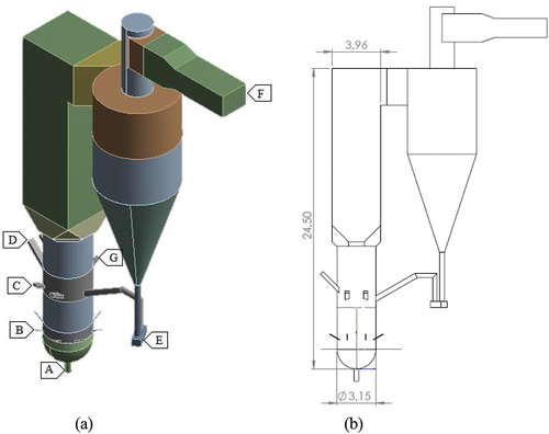
Figure illustrates the CFB geometry of the boiler, which has a ring baffle on the side of the furnace. The ring baffle is located close to the inlet channel on the first ring baffle at an altitude of 4,175 m and on the second ring baffle at an altitude of 8,560 m. The ring baffle is a half-ellipse that circumnavigates the furnace wall. The half-elliptical shape aims to minimize the voltage centered on the ring baffle area. In addition, the elliptical shape prevents particles from settling and becoming trapped in the ring baffle. For the application, the ring baffle can be applied by the structure modification inside the furnace. The addition of eclipse areas using the same material as the furnace wall. Length dimensions in the form of the major axis of the ellipse (L) and depth dimensions in the form of the minor axis of the ellipse (D) of the ring baffle are depicted in Figure , and the variations in dimensions are depicted in Table . There are between one and two baffle rings used. The ellipse has a fixed length of 1 m, while its depth ranges from 0.15 m to 0.45 m. Figure illustrates the geometry of the furnace with ring baffle variants. As depicted in Figure , the discretization process is carried out by dividing the body into several parts so that tetrahedral and hexahedral meshes can be produced. As depicted in Figure , the grid independence test was conducted on elements with the following sizes: 0.15 m, 0.2 m, 0.25 m, and 0.3 m, and the resulting element counts were 723,074, 405194, 279679, and 231,178. A grid with 0.25 m elements and a skewness of 0.814 (acceptable) can produce a difference of 2.12% against the size of the smallest element and 0.02% against the size of the largest element when testing the airspeed in the outlet area (ANSYS Inc., Citation2015). To obtain simulation data, the use of a 0.25 m element size is based on saving time and co-computing costs. The conversion of tetrahedral mesh to polyhedral mesh is performed to enhance the speed and precision of simulation results.
Figure 2. Geometry of a CFB boiler with a ring baffle on the right and rear sides of the furnace.
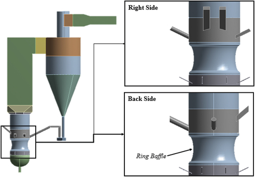
Figure 3. Dimensions of ring baffle.
Figure 4. Furnace geometry with variations in the number and depth of ring baffle.
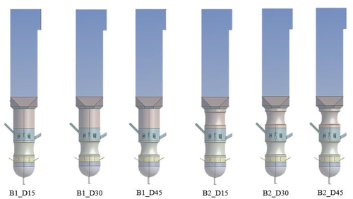
Figure 5. Meshed domain of CFB boilers.
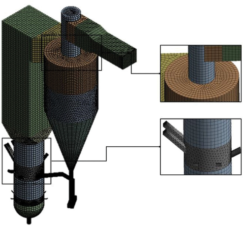
Figure 6. Independence grid test.
Table 1. Variations in the number and depth of ring baffles
3.2. Simulation procedure
A multiphase flow model that accounts for the interaction between solid particles and air was used to guide the simulations, which were carried out using the ANSYS Fluent 19.2 program. Since the present study is primarily concerned with the ring baffle geometry, which has an impact on the erosion phenomenon, the case is simplified by the use of monofractional bed particles. The pressure-based model solver is utilized in Table gives a summary of the characteristics of the solid particles that will be simulated. The patch of 0.15 solid particles receives the application of the furnace and seal pot. To achieve steady-state conditions, the simulation was conducted using time steps of 5 × 10⁻³ s for a total of 30 s. Table details the characteristics of the air mass flow rate from each inlet. Note that the type of air distributor is the mass flow type in the gauge pressure. The inlet pipe is modelled using a round shape, and the air is injected normal to the pipe boundary.
Table 2. Solver model on ANSYS Fluent 19.2
Table 3. Properties of solid particles
Table 4. Mass flow inlet
3.3. Validation
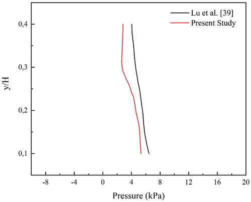
Simulations that have been executed must be compared to simulations that have been executed in the same conditions in the past. This is performed to ensure the simulation’s validity. The validation process compares the pressure drop of the CFB boiler at heights ranging from 2.25 to 9 m. The validation process yielded a pressure drop value of 2.5088 kPa, while the standard is 2.4052 kPa. Figure depicts a comparison between the pressure drop value from the simulation of Lu et al. and the present study, which has an error of 4.3% (Lu et al., Citation2013). Y represents the full height of the furnace, while y represents the height at the sample point.
Figure 7. Validation result.
4. Results and discussion
4.1. Pressure distribution
The distribution of pressure is a measurable parameter that can be measured experimentally. However, running variations in experiments require a great deal of time and money. Thus, CFD is very useful for making predictions based on variations in collected data.
The fluidization process that occurs in the CFB boiler’s furnace is influenced by pressure. Figure depicts a graph of the pressure distribution within the furnace in which all variations have the same distribution. From Figure , it can be determined that the pressure at the bottom is greater than the pressure at the top, which is at a height of 22.5 m. Feng explains that this phenomenon cannot be separated from the presence of ring baffles, which can cause an increase in pressure drop, resulting in higher initial energy demand (Feng et al., Citation2018).
Figure 8. Pressure distribution.
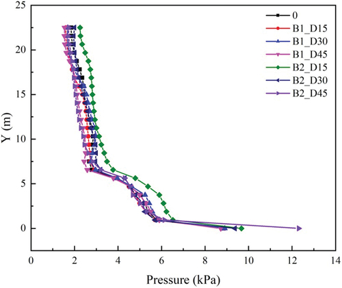
A significant difference in the pressure drop occurs in the variation B2_D45 where at the bottom of the furnace the resulting pressure is 12.3 kPa. In other variations, the pressure range at that position is between 8.84 and 9.37 kPa. In this way, the pressure drop generated in the B2_D45 variation is greater than in the other variations. If we look at the pressure drop in the variation without a ring baffle, the pressure at the bottom of the furnace is 8.84 kPa which is the smallest of all variations. Due to the existence of ring baffles that can increase the pressure drop, the pressure at the bottom of the furnace needs to be considered to avoid fatigue. Benzarti’s research also revealed that pressure drop is a parameter that gives full consideration when adding baffle rings into the furnace because of the flow distraction which causes the pressure in the system to decrease or the energy required tends to increase (Benzarti et al., Citation2021). Ergun’s research on fluidized beds in 1952 provides a general outlook of the relationship between pressure drop and other parameters in Equation 15 as follows (Ergun, Citation1952).
The pressure inside the boiler’s CFB is closely related to other factors, according to the equation. The internal pressure will rise as the distance between the two sampling locations, air density, dynamic viscosity, and surface velocity of the bed all increase. The pressure inside the furnace will drop as particle volume percentages, sphericity, and diameter rise. In the correlation that follows, Ergun also offers details on the connection between pressure loss and particle friction in the CFB (Allen et al., Citation2013).
EquationEquation 16(16)
(16) takes into account friction caused by the presence or absence of a ring baffle, where both circumstances can exist. It should be noted that the Ergun friction factor fErg is only appropriate for smooth spheres, not packed beds of rock or other non-spherical particles, as measured values can deviate up to 100% or more from the Ergun equation.
4.2. Particle volume fraction analysis
In chemical terms, the volume fraction (φi) is defined as the volume of an element (Vi) divided by its mixed volume (Vj). As a nondimensional number, the volume fraction has a value between 0 and 1. In addition, the volume fraction can be written as a percent of the volume (%vol). Equation 17 can be seen as follows.
While it is challenging to achieve in an experimental procedure, the distribution of particle volume fractions acquired from simulations is tremendously helpful for understanding the fluidization process that takes place inside the furnace of a CFB boiler.
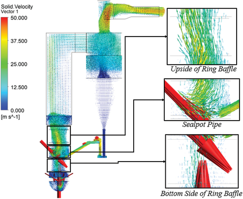
The contours of the particle volume fraction on the boiler’s furnace region are shown in Figure in increments of 30 s. On the red contour, particles that are returning to the furnace through the sealpot pipe collect in the area of the furnace wall across from the sealpot pipe when the particle volume fraction is set to its maximum value of 0.05. The majority of the particles that hit the opposite wall are concentrated here. If this condition continues, there is a greater chance that the wall may erode, which will eventually cause the furnace wall material to fail.
Figure 9. Variations in ring baffle ring volume fractions in furnaces.
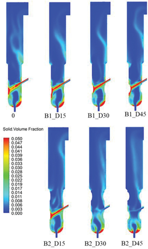
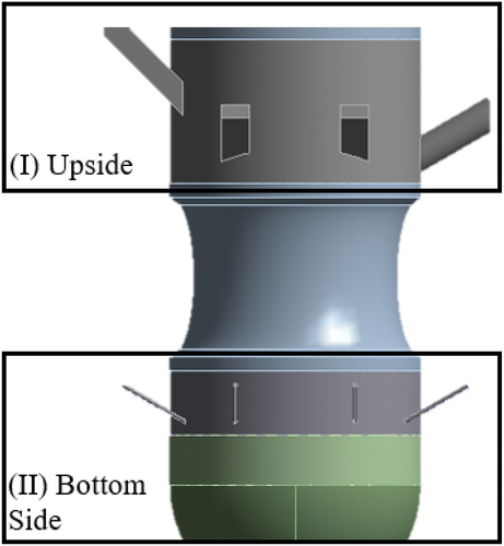
Figure shows how dramatically different the volume fraction contours of particles in the same range as the number and depth of the ring baffle are. When redistributing particles that re-enter the furnace, boilers with a single ring baffle in the CFB version have distinctive flow characteristics. For variations in B1_D15, the volume proportion of particles tends to be spread along the walls in the lower areas of the ring baffle. This is because the ring baffle’s half-ellipse geometry, which can accommodate the particle flow distribution so that it is scattered across the surface and does not settle in a single location, is responsible for this. Although there is a greater concentration of particles than in variant B1_D15, the volume proportion of particles in variation B1_D30 is still distributed to the upper and lower regions of the ring baffle. The air pressure before passing through the ring baffle is higher than the air pressure after passing through the ring baffle when the ring baffle cross-sectional area is reduced. The base of the furnace will experience pressure due to air coming from the primary air inlet and lower secondary air inlet. As a result, the particle flow that is spread along the ring baffle is obstructed by the air pressure from the furnace floor. It is challenging to obstruct the particle flow, nonetheless, because the primary air inlet’s airspeed is lower than the sealpot pipe’s particle velocity. The ring baffle’s role as a nozzle and application of the Bernoulli relationship in EquationEquation 18(18)
(18) can be used to explain this phenomenon (Cengel & Cimbala, Citation2006).
Figure can be used to understand EquationEquation 18(18)
(18) . The difference in air velocity through the baffle ring and the amount of pressure on the upper and lower sides are equal. From this, it may be inferred that the lower side pressure exceeds the upper side pressure. In contrast, the upper side’s speed is greater than the lower side’s. As a result, the air pressure before the baffle ring is opened is higher than the air pressure after the baffle ring has been opened. The B1_D45 variation serves as a good example of this, showing how the particle volume fraction appears to be distributed uniformly throughout the baffle ring wall despite the fact that the bottom side’s pressure has been transformed to air velocity and is therefore insufficient to sustain the flow of particles impacting the baffle ring.
Figure 10. Bottom (I) and top (II) ring baffle.
A CFB boiler with two baffle rings can evenly distribute the volume fraction. In comparison to the variation of a single ring baffle, the variation of B2_D30 and B2_D45 demonstrates a very good distribution of particle volume fraction. Due to the upper baffle ring’s success in increasing the pressure on the lower baffle ring, there is no accumulation of particles on the baffle ring wall opposite the sealpot pipe. In addition, the ring baffle’s small cross-sectional area allows the airflow velocity from the primary air inlet in order to deflect the particle flow away from the seal pot. This does not occur in the B2_D15 variation, which has a particle volume fraction contour similar to that of the CFB boiler without a baffle ring. This is because of its cross-sectional area nearly identical to the variation without a baffle ring, preventing it from diverting the particle flow away from the sealpot pipe.
In each variation, the particle volume fraction near the primary air inlet settles along a similar contour. This is unavoidable if the bottom surface of the furnace does not fully circulate air, resulting in a dead zone (Wang et al., Citation2019). Thus, the fundamental geometry of the furnace affects particle flow.
The relationship between the particle volume fraction distribution and the height of the furnace is depicted in Figure . The graph indicates that the particle volume fraction is greatest at an altitude of 4.69 m. Both variants of 0, B1_D15, B1_D30, B1_D45, and B2_D15 have particle volume fraction values in the range of 0.04 to 0.05. This value is inversely proportional to the B2_D30 and B2_D45 values of 0.009 and 0.00089, respectively.
Figure 11. Variations in particle volume fraction distribution on ring baffles.
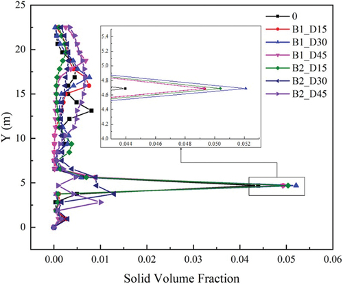
At a height of 4.69 m, the variation B2_D45 has the smallest volume fraction relative to other variations, illustrating the relationship between pressure and particle volume fraction. On the pressure distribution graph, it is clear that a higher pressure is required to produce the smallest volume fraction in the region close to the recirculation pipe, where there is no particle accumulation. Comparatively, the volume fraction of the particles found at a height of 4.69 m is greater than the variation of B2_D30, indicating that there is no high pressure at the bottom of the furnace.
With a high volume fraction of particles in a particular area, Samruamphianskun’s research indicates that the fluidization process in the CFB boiler will result in a non-uniform mixing of air, particles, and fuel (Samruamphianskun et al., Citation2012). This is also consistent with Liu’s research, which indicates that the accumulation of particles in certain areas will reduce the velocity of the incoming air and increase the pressure in the furnace’s lower region (Liu et al., Citation2017).
4.3. Velocity distribution
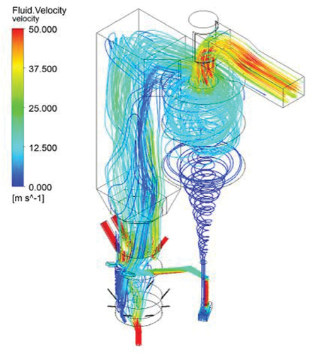
Figure depicts a CFB boiler with a streamlined flow of air inside of it. The inlet channels consist of the primary air inlet, the lower secondary air inlet, the fuel chute inlet, the upper secondary air inlet, the fluidized air inlet, and the water inlet seal pot. Figure demonstrates that the air rises in the furnace region before entering the cyclone separator. A portion of the air in the cyclone separator exits through the outlet channel and partially returns to the furnace via the seal pot.
Figure 12. Streamline of air velocity inside the CFB boiler.
In Figure , the particle velocity vector flow in the CFB Boiler variation B2_D30 can be observed. In the enlarged section, it can be viewed that the area below the baffle ring has a higher velocity than other areas, so that it pushes the particles that exit the sealpot pipe to the top of the furnace. As a result of the collision between the particle flow from below and the particle flow from the sealpot pipe, the air velocity from the upper secondary air inlet decreases the particle flow velocity in the lower ring baffle area.
Figure 13. Variations in B2 D30 particle flow velocity vectors in furnace regions.
4.3.1. Particle axial velocity distribution
Figure depicts a graph of the particles’ axial velocity distribution. Each variation, both with and without a ring baffle, is observed to have a distinct distribution. According to Wang’s research, the axial velocity distribution produces a zigzag pattern in the ring baffle region when viewed in greater detail (Wang et al., Citation2019). Extreme axial velocity is reached at a height of 0.94 m, where the CFB boiler variation B2_D45 has its highest value, 33.93 m/s in a vertically upward direction. In addition, a high downward axial velocity occurs at an altitude of 4.69 m, where the CFB boiler variation B2_D15 has its highest value of 9.4 m/s in a downward direction. However, the axial velocity decreases in the B2_D45 variation when all other variations, except for the B2_D30 variation, have a high inward axial velocity.
Figure 14. Distribution of particle axial velocity on ring baffle variations.
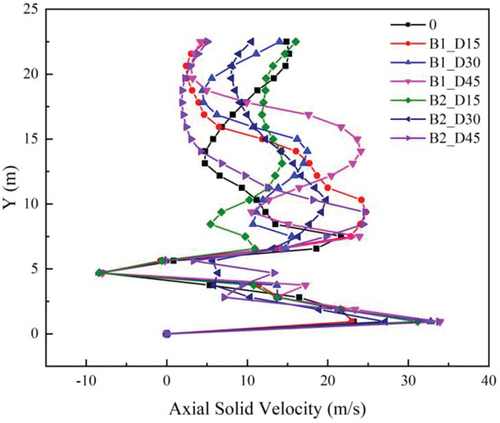
The variation with the lowest axial velocity is B2_D30, which lacks a dominant velocity at each height compared to other variations. Thus, the variation of B2_D30 is believed to be capable of reducing the impact of erosion as a result of the axial velocity of the particles, which will influence the generated momentum. If the velocity fluctuation at each height is greater than in other variations, the axial velocity of particles in a variation can have a significant effect on erosion. Uzi’s research revealed a correlation between the axial particle velocity and the velocity of their collision with the wall (Uzi et al., Citation2017). In addition, Zhang provides the relationship between the axial velocity of particles and the average particle volume fraction in EquationEquation 19(19)
(19) (Zhang et al., Citation2021):
where the volume fraction of the typical particle is inversely proportional to its axial velocity. Figure shows that a sample point with a height of 4.69 m has an inversely proportional relationship with the particle’s axial velocity distribution. With an increase in particle concentration in certain regions, the axial velocity tends to decrease, thereby increasing the likelihood of erosion.
4.3.2. Radial velocity distribution of particles
Next, Figure depicts the distribution of particle radial velocity. Variations in the number and depth of ring baffles are observed to result in significantly different radial velocity distribution differences. For instance, in variations, B1_D15 and B1_D45, the radial velocity towards the wall at an altitude of 4.69 m is 7.29 m/s and 8.73 m/s, respectively. However, both variations have the greatest radial velocity toward the furnace’s center at an altitude of 6.56 m, i.e. 4.04 and 4.66 m per second. Compared to variations in one ring baffle, variations in two ring baffles have a less dominant radial velocity distribution because there is no extreme velocity outward at a particular height.
Figure 15. Variations in the radial velocity distribution of particles on ring baffles.
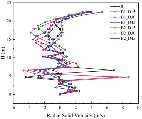
Momentum on the surface of the furnace wall is influenced by both axial and radial velocities. Following Chen’s research, turbulent flows generate radial particle motions that result in numerous collisions with the walls, leading to an erosion zone (Chen et al., Citation2015). In addition to causing erosion, high-speed and high-intensity collisions will cause surface fatigue on the furnace wall. Therefore, it is best to avoid the possibility of erosion caused by radial velocity.
4.4. Shear stress
The definition of shear stress is a force acting on a specific area that intersects with the cross-section on which the force acts. Erosion rate is directly proportional to shear stress. Fluid particles circulating in the CFB of the boiler necessitate an analysis of their effect on shear stress-induced erosion. Bitter et al. state that when a particle strikes a flat surface with a tapered angle, the material emptied by the axle must be accounted for as shear stress (Bitter, Citation1963).
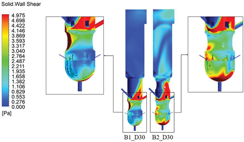
Figure depicts the contours of the particle shear stress on the furnace wall when the maximum pressure is set to 5 Pa. The region near the air inlet line has high shear stress. One cause is the flow of particles reentering the furnace from the sealpot pipe, where a portion of the particles’ volume accumulates on the furnace wall opposite the sealpot pipe. In addition, the influence of the introduced primary air causes particles that have recently exited the fluidized sealpot pipe to strike the walls above.
Figure 16. Comparison of shear stress curves in furnaces with variations in ring baffles.
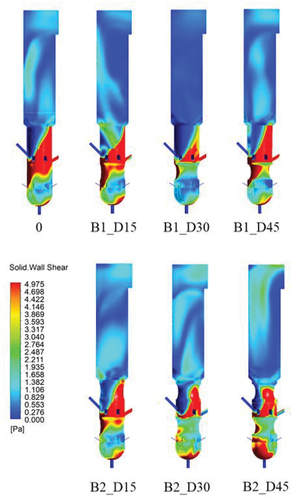
Moreover, the B1_D15, B1_D45, and B2_D15 variants have the same shape as CFB boilers without ring baffles. The variations B1_D30 and B2_D45 share similarities regarding the particles entering the furnace via the sealpot pipe. A ring baffle can reduce the effect of shear stress on the walls above it. The variation B2 D30 demonstrates the best performance of the ring baffle, as the shear stress in the region opposite the sealpot pipe has the lowest value compared to other variations. The trend of the obtained results is comparable to the particle volume fraction profile described in section 4.2.1. This can be demonstrated through the relationship between the particle volume fraction and shear stress studied by Papathanassiou in equation 20 (Papathanassiou et al., Citation1983).
where X is a variable that relates the volume fraction to the shear stress in a two-phase flow consisting of particles and air. The relationship between the particle volume fraction and the particle shear stress is directly proportional so that the contours produced by the two are not significantly different. In addition, a similar correlation is observed between the axial and radial velocities of particles, where the maximum value that is not excessively high in comparison to other variations will have a significantly more uniform particle distribution.
As seen in Figure , variation B1_D30 has a better shear stress contour at the base of the furnace than variation B2_D30, whereas variation B2_D30 has a better shear stress contour in the area opposite the sealpot pipe. A portion of the sealpot pipe’s particles will follow the airflow, while the remainder will be trapped at the bottom of the furnace. In variation B2_D30, the presence of two ring baffles directs particles to the center of the furnace, causing areas of particle accumulation. However, the flow of such particles quickly dispersed from the furnace’s center. Due to the effect of narrowing, Rossbach termed this phenomenon narrowing expansion (Rossbach et al., Citation2019). If the surface of the furnace base is an inlet channel, the possibility of erosion caused by shear tension at the bottom of the furnace can be ignored. Consequently, the potential for erosion caused by shear stresses can be avoided.
Figure 17. Narrowing-expansion effect on furnace base.
5. Conclusion
The following conclusions can be drawn after data analysis and discussions of hydrodynamic analysis and erosion potential:
The pressure drop produced by a CFB boiler is affected by variations in the number and depth of ring baffles, and this pressure drop is higher with ring baffles than without. Simulations have demonstrated that the pressure drop has an inverse relationship with increasing ring baffle depth in the variation of a single ring baffle. While the variation of two ring baffles continues to follow the same trend, pressure is building on variation B2_D45 as a result of the decrease in cross-sectional area in the ring baffle region. Additionally, the percentage of particle volume returning to the furnace from the sealpot pipe increases the pressure drop.
Changes in ring baffle depth and number have an impact on particle volume fraction. Other variations maintain a high volume fraction profile, especially on the furnace wall across from the sealpot pipe. Avoiding localized high particle volume fractions is necessary to reduce the impact of erosion brought on by the intensity of the impact that occurs in a particular location.
Variation B2_D30 has axial and radial velocities in the ring baffle region with maximum values of 27.1 m/s and 2.46 m/s, resulting in a pressure drop value of 7.38 kPa where the value is not dominant in each parameter relative to other variations.
Shear stress is additionally used as a catalyst to lessen the effects of erosion. B2_D30 variations are dependable for reducing erosion impacts because their impact is directly proportional to the particle volume fraction.
Nomenclature
d diameter, m
L distance of the review point
H altitude, m
p pressure, Pa
t time,s
U superficial airspeed
V speed, m/s
x x-axis directional position component
y components of the position of the direction of the y-axis
z z-axis directional position component
u x-axis directional velocity component
v y-axis directional velocity component
w z-axis directional velocity component
x k kinetic energy
S kinetic energy turbulent generator
Greek Letters
β angle of impingement
ε erosion rate
σy voltage
φ volume fractions
ρ density
ω specific dissipation rate
μ dynamic viscosity
τ shear stress
y sphericity
Subscripts
s solid phase
g gas phase
p particles
S Turbulent
Disclosure statement
No potential conflict of interest was reported by the authors.
Additional information
Funding
Notes on contributors

M.S.K. Tony Suryo Utomo
M.S.K. Tony Suryo Utomo, S.T., M.T., Ph.D., is a lecturer who is permanently teaching at Diponegoro University (UNDIP) Semarang. He received his Bachelor of Engineering (S.T.) degree at the Department of Mechanical Engineering UNDIP in 1996. He continued his master's degree at the Department of Mechanical Engineering, Bandung Institute of Technology and earned a Master of Engineering (M.T.) in 2003. His latest education is a Doctor of Philosophy degree (Ph.D.) from Gyeongsang National University, South Korea, in 2008. Until today, he has been actively teaching at the Mechanical Engineering Department UNDIP by teaching some energy conversion courses including Fluid Mechanics, Thermodynamics, Heat Transfer, CFD, and Renewable Energy. Currently, he is researching co-firing steam generator, thermal dispersion, fluidized bed drying, and multi-effect desalination with thermovapor compressor systems.
Ir. Eflita Yohana
Eflita Yohana Prof. Ir. Eflita Yohana, M.T., Ph.D., is a lecturer who is permanently teaching at Diponegoro University (UNDIP) Semarang. She received her Bachelor of Engineering (ST) degree from the Department of Mechanical Engineering, Universitas Brawijaya (UB) Malang in 1986. Master of Engineering (MT) was obtained from the Department of Mechanical Engineering, Gadjah Mada University (UGM) in 1999. He continued his doctoral level until she obtained a Doctor of Philosophy (Ph.D.) degree in 2011 from Pukyong National University, South Korea. Until today, he has been actively teaching at the Department of Mechanical Engineering by teaching some energy conversion courses, including Thermodynamics, Fluid Mechanics, Heat Transfer, and Steam Generation. He is currently researching spray drying.
References
- Allen, K. G., von Backström, T. W., & Kröger, D. G. (2013). Packed bed pressure drop dependence on particle shape, size distribution, packing arrangement and roughness. Powder Technology, 246, 590–23. https://doi.org/10.1016/j.powtec.2013.06.022
- ANSYS, Inc. (2009). ANSYS user Guide (12.0).
- ANSYS Inc. (2015). Mesh quality and advanced topics ansys workbench 16.0. Ansys, 1–37.
- Basu, P. (2015). Circulating fluidized bed boilers : Design, operation and maintenance. In Thermal engineering (Vol. 54, 6). Springer International Publishing Switzerland. https://doi.org/10.1007/978-3-319-06173-3
- Benzarti, S., Mhiri, H., & Bournot, H. (2021). Numerical simulation of baffled circulating fluidized bed with geldart B particles. Powder Technology, 380, 629–637. https://doi.org/10.1016/j.powtec.2020.11.033
- Bitter, J. G. A. (1963). A study of erosion phenomena part I. Wear, 6(1), 5–21. https://doi.org/10.1016/0043-1648(63)90003-6
- Bu, J., & Zhu, J. X. (1999). Influence of ring-type internals on axial pressure distribution in circulating fluidized bed. Canadian Journal of Chemical Engineering, 77(1), 26–34. https://doi.org/10.1002/cjce.5450770106
- Cengel, Y. A., & Cimbala, J. M. (2006). Fluid Mechanics: Fundamentals and applications. McGraw-Hill.
- Chandimal Bandara, J., Sørflaten Eikeland, M., & Moldestad, B. M. E. (2017). Analyzing the effects of particle density, size, size distribution and shape for minimum fluidization velocity with Eulerian-Lagrangian CFD simulation. Proceedings of the 58th Conference on Simulation and Modelling (SIMS 58) Reykjavik, Iceland, September 25th – 27th, 2017, 138, 60–65. https://doi.org/10.3384/ecp1713860
- Chen, J., Wang, Y., Li, X., He, R., Han, S., & Chen, Y. (2015). Erosion prediction of liquid-particle two-phase flow in pipeline elbows via CFD-DEM coupling method. Powder Technology, 275, 182–187. https://doi.org/10.1016/j.powtec.2014.12.057
- Darihaki, F., Zhang, J., Vieira, R. E., & Shirazi, S. A. (2021). The near-wall treatment for solid particle erosion calculations with CFD under gas and liquid flow conditions in elbows. Advanced Powder Technology, 32(5), 1663–1676. https://doi.org/10.1016/j.apt.2021.03.020
- Ergun, S. (1952). Fluid flow through packed columns. Chemical Engineering Progress, 48, 89–94. https://doi.org/10.1021/ie50474a011
- Farokhipour, A., Mansoori, Z., Rasteh, A., Rasoulian, M. A., Saffar-Avval, M., & Ahmadi, G. (2019). Study of erosion prediction of turbulent gas-solid flow in plugged tees via CFD-DEM. Powder Technology, 352, 136–150. https://doi.org/10.1016/j.powtec.2019.04.058
- Feng, X., Shen, L., & Wang, L. (2018). Effect of baffle on hydrodynamics in the air reactor of dual circulating fluidized bed for chemical looping process. Powder Technology, 340, 88–98. https://doi.org/10.1016/j.powtec.2018.09.012
- Gandhi, M. B., Vuthaluru, R., Vuthaluru, H., French, D., & Shah, K. (2012). CFD based prediction of erosion rate in large scale wall-fired boiler. Applied Thermal Engineering, 42, 90–100. https://doi.org/10.1016/j.applthermaleng.2012.03.015
- Gidaspow, D. (1986). Hydrodynamics of fluidization of single and binary size particles: Supercomputer modeling. Applied Mechanics Reviews, 39(1), 1–23. https://doi.org/10.1115/1.3143702
- Gu, J., Shao, Y., & Zhong, W. (2020). 3D simulation on pressurized oxy-fuel combustion of coal in fluidized bed. Advanced Powder Technology, 31(7), 2792–2805. https://doi.org/10.1016/j.apt.2020.05.005
- Jiang, P., Bi, H., Jean, R. H., & Fan, L. S. (1991). Baffle effects on performance of catalytic circulating fluidized bed reactor. AIChE Journal, 37(9), 1392–1400. https://doi.org/10.1002/aic.690370911
- Kang, R., & Liu, H. (2020). An integrated model of predicting sand erosion in elbows for multiphase flows. Powder Technology, 366, 508–519. https://doi.org/10.1016/j.powtec.2020.02.072
- Lin, N., Arabnejad, H., Shirazi, S. A., McLaury, B. S., & Lan, H. (2018). Experimental study of particle size, shape and particle flow rate on erosion of stainless steel. Powder Technology, 336, 70–79. https://doi.org/10.1016/j.powtec.2018.05.039
- Liu, H., Li, J., & Wang, Q. (2017). Simulation of gas–solid flow characteristics in a circulating fluidized bed based on a computational particle fluid dynamics model. Powder Technology, 321, 132–142. https://doi.org/10.1016/j.powtec.2017.07.040
- Li, N., Zhang, Y., Jiang, F., Qi, G., Wang, H., Su, R., Zhang, W., & Shi, N. (2020). Joint effects of liquid level and baffle height on the particle distribution and pressure drop in a vertical two-pass circulating fluidized bed evaporator with a baffle. Powder Technology, 364, 27–35. https://doi.org/10.1016/j.powtec.2020.01.063
- Li, N., Zhang, Y., Jiang, F., Wang, H., & Li, X. (2020). Effects of particle type on the particle distribution in a two-pass circulating fluidized bed evaporator with baffle. Powder Technology, 366, 1–11. https://doi.org/10.1016/j.powtec.2020.02.038
- Lopes, G. C., Rosa, L. M., Mori, M., Nunhez, J. R., & Martignoni, W. P. (2011). Three-dimensional modeling of fluid catalytic cracking industrial riser flow and reactions. Computers and Chemical Engineering, 35(11), 2159–2168. https://doi.org/10.1016/j.compchemeng.2010.12.014
- Lu, B., Zhang, N., Wang, W., & Li, J. (2013). 3-D full-loop simulation of an industrial-scale circulating fluidized-bed boiler. AIChE Journal, 59(4), 1108–1117. https://doi.org/10.1002/aic.13917
- Marchelli, F., Hou, Q., Bosio, B., Arato, E., & Yu, A. (2020). Comparison of different drag models in CFD-DEM simulations of spouted beds. Powder Technology, 360, 1253–1270. https://doi.org/10.1016/j.powtec.2019.10.058
- Mbabazi, J. G., & Sheer, T. J. (2004). Numerical Prediction of Erosion of Mild Steel Surfaces by Boiler Fly Ash Particles, 1, 595–604. https://doi.org/10.1115/ESDA2004-58074
- Menter, F. R. (1993). Zonal two equation k-ω turbulence models for aerodynamic flows. AIAA Paper, 93–2906.
- Mirek, P. (2020). Air Distributor pressure drop analysis in a circulating fluidized-bed boiler for non-reference operating conditions. Chemical Engineering and Technology, 43(11), 2233–2246. https://doi.org/10.1002/ceat.201900565
- Muhammad, A., Zhang, N., & Wang, W. (2019). CFD simulations of a full-loop CFB reactor using coarse-grained Eulerian–Lagrangian dense discrete phase model: Effects of modeling parameters. Powder Technology, 354, 615–629. https://doi.org/10.1016/j.powtec.2019.06.016
- Namkung, W., & Kim, S. D. (1998). Gas backmixing in a circulating fluidized bed. Powder Technology, 99(1), 70–78. https://doi.org/10.1016/S0032-5910(98)00092-8
- Papathanassiou, G., Maeder, P. F., DiPippo, R., & Dickinson, D. A. (1983). Void fraction correlations in two-phase horizontal flow. Brown University Providence.
- Pinheiro, C. I. C., Fernandes, J. L., Domingues, L., Chambel, A. J. S., Graça, I., Oliveira, N. M. C., Cerqueira, H. S., & Ribeiro, F. R. (2012). Fluid catalytic cracking (FCC) process modeling, simulation, and control. Industrial and Engineering Chemistry Research, 51(1), 1–29. https://doi.org/10.1021/ie200743c
- Qi, G., & Jiang, F. (2015). Parametric study of particle distribution in tube bundle heat exchanger. Powder Technology, 271, 210–220. https://doi.org/10.1016/J.POWTEC.2014.11.012
- Rossbach, V., Utzig, J., Decker, R. K., Noriler, D., & Meier, H. F. (2016). Numerical gas-solid flow analysis of ring-baffled risers. Powder Technology, 297, 320–329. https://doi.org/10.1016/j.powtec.2016.04.044
- Rossbach, V., Utzig, J., Decker, R. K., Noriler, D., Soares, C., Martignoni, W. P., & Meier, H. F. (2019). Gas-solid flow in a ring-baffled CFB riser: Numerical and experimental analysis. Powder Technology, 345, 521–531. https://doi.org/10.1016/j.powtec.2018.12.096
- Samruamphianskun, T., Piumsomboon, P., & Chalermsinsuwan, B. (2012). Effect of ring baffle configurations in a circulating fluidized bed riser using CFD simulation and experimental design analysis. Chemical Engineering Journal, 210, 237–251. https://doi.org/10.1016/j.cej.2012.08.079
- Tarodiya, R., & Levy, A. (2021). Surface erosion due to particle-surface interactions - A review. Powder Technology, 387, 527–559. https://doi.org/10.1016/J.POWTEC.2021.04.055
- Therdthianwong, A., Pantaraks, P., & Therdthianwong, S. (2003). Modeling and simulation of circulating fluidized bed reactor with catalytic ozone decomposition reaction. Powder Technology, 133(1–3), 1–14. https://doi.org/10.1016/S0032-5910(03)00120-7
- Utzig, J., De Souza, F. J., & Meier, H. F. (2014). A numerical analysis of the turbophoresis in a turbulent gas-particle flow. American Society of Mechanical Engineers, Fluids Engineering Division (Publication) FEDSM, 1C, 13–14. https://doi.org/10.1115/FEDSM2014-21993
- Uzi, A., Ben Ami, Y., & Levy, A. (2017). Erosion prediction of industrial conveying pipelines. Powder Technology, 309, 49–60. https://doi.org/10.1016/j.powtec.2016.12.087
- Van de Velden, M., Baeyens, J., & Smolders, K. (2007). Solids mixing in the riser of a circulating fluidized bed. Chemical Engineering Science, 62(8), 2139–2153. https://doi.org/10.1016/j.ces.2006.12.069
- Versteeg, H. K., & Malalasekera, W. (1995). An introduction to computational Fluid dynamics: The finite volume method (1st ed.). Longman Scientific & Technical.
- Wanchan, W., Khongprom, P., & Limtrakul, S. (2020). Study of wall-to-bed heat transfer in circulating fluidized bed riser based on CFD simulation. Chemical Engineering Research and Design, 156, 442–455. https://doi.org/10.1016/j.cherd.2020.02.021
- Wang, S., Luo, K., Hu, C., & Fan, J. (2018). Particle-scale investigation of heat transfer and erosion characteristics in a three-dimensional circulating fluidized bed. Industrial and Engineering Chemistry Research, 57(19), 6774–6789. https://doi.org/10.1021/acs.iecr.8b00353
- Wang, S., Luo, K., Hu, C., & Fan, J. (2019). CFD-DEM study of the effect of ring baffles on system performance of a full-loop circulating fluidized bed. Chemical Engineering Science, 196, 130–144. https://doi.org/10.1016/j.ces.2018.10.056
- Wang, P., Yao, X., Yang, H., & Zhang, M. (2014). Impact of particle properties on gas solid flow in the whole circulating fluidized bed system. Powder Technology, 267, 193–200. https://doi.org/10.1016/j.powtec.2014.06.065
- Wu, Y., Liu, D., Duan, L., Ma, J., Xiong, J., & Chen, X. (2018). Three-dimensional CFD simulation of oxy-fuel combustion in a circulating fluidized bed with warm flue gas recycle. Fuel, 216(October 2017), 596–611. https://doi.org/10.1016/j.fuel.2017.12.042
- Xu, L., Cheng, L., Cai, Y., Liu, Y., Wang, Q., Luo, Z., & Ni, M. (2016). Heat flux determination based on the waterwall and gas-solid flow in a supercritical CFB boiler. Applied Thermal Engineering, 99, 703–712. https://doi.org/10.1016/j.applthermaleng.2016.01.109
- Xu, Y., Musser, J., Li, T., Gopalan, B., Panday, R., Tucker, J., Breault, G., Clarke, M. A., & Rogers, W. A. (2018). Numerical simulation and experimental study of the gas-solid flow behavior inside a full-loop circulating fluidized bed: Evaluation of different drag models. Industrial and Engineering Chemistry Research, 57(2), 740–750. https://doi.org/10.1021/acs.iecr.7b03817
- Zhang, N., Lu, B., Wang, W., & Li, J. (2010). 3D CFD simulation of hydrodynamics of a 150MWe circulating fluidized bed boiler. Chemical Engineering Journal, 162(2), 821–828. https://doi.org/10.1016/j.cej.2010.06.033
- Zhang, R., Zhao, X., Zhao, G., Dong, S., & Liu, H. (2021). Analysis of solid particle erosion in direct impact tests using the discrete element method. Powder Technology, 383, 256–269. https://doi.org/10.1016/j.powtec.2021.01.034