
 ?Mathematical formulae have been encoded as MathML and are displayed in this HTML version using MathJax in order to improve their display. Uncheck the box to turn MathJax off. This feature requires Javascript. Click on a formula to zoom.
Abstract
The use of steel fibres in reinforcing concrete has proven to enhance certain mechanical and durability properties of concrete; however, as a material that presents enhanced properties, its environmental performance should also be analysed. This study aims to quantify the carbon emissions of steel fibre-reinforced concrete beams using a functional unit that considers the mechanical and durability performance of concrete through a whole life cycle assessment methodology that includes the benefits/load after the end-of-life. A cradle-to-grave approach, which considers the end-of-life stage and the benefits/loads beyond the system boundary, was performed to compare the embodied carbon of conventionally reinforced concrete and steel fibre-reinforced concrete beams. The results show that the addition of steel fibres as reinforcing material to concrete can reduce the area of steel required in the tension zone of a conventionally reinforced concrete beam and the embodied carbon of concrete by an average of 33% and 37%, respectively.
Reviewing Editor:
1. Introduction
Climate change, which is a result of greenhouse gas emissions, poses a significant impact on the environment. With changes in precipitation, rise in temperatures and flooding, the effects of climate change are being experienced across the world. Globally, carbon dioxide emissions from the energy sector, which includes electricity and heat, transportation, building, manufacturing and construction, increased from 24.3 Gt in 2000 to 36.3 Gt in 2021 (International Energy Agency [IEA], Citation2022b). Building and construction contribute about 37% of the carbon emissions from the sector (United Nations Environment Programme, Citation2022). Improvements to the built environment and urbanisation have increased the demand for various construction materials. Most buildings and infrastructure are made using concrete and steel materials mainly as these materials are able to resist, to an extent, the effect of environmental changes and applied loads on them. Globally, concrete is one of the most widely used construction materials due to its advantageous properties over most construction materials. However, it is responsible for about 8% of global anthropogenic carbon dioxide emissions (Lippiatt et al., Citation2020). Typical in-situ concrete is made up of primarily cement (10%), fine aggregate (25%), coarse aggregate (45%), water (18.5%) and air (1.5%). Cement, however, is considered to have the highest embodied carbon among all these constituents (Jones, Citation2019). Cement is produced in a capital and energy-intensive plant which emits carbon dioxide (CO2) as an end-product during the production of clinker (Gibbs et al., Citation2000). Between 2015 and 2021, the CO2 intensity of cement manufacturing increased by 1.5% annually and to achieve net zero carbon emissions by 2050, an annual reduction of about 3% of these CO2 emissions is required (IEA, Citation2022a). With the increasing demand for cement-based materials, reducing the amount of carbon dioxide emitted will be challenging. Various strategies are being adopted to cut the carbon emissions in these cement-based materials, and this includes the use of alternative materials to replace some of the primary constituents of the material, the use of alternative fuels for cement production and the use of lower concrete grades in parametric design optimisation.
In structural design, materials such as steel rebars and fibres such as bamboo fibres, steel fibres and polypropylene fibres are added to the concrete as a reinforcement to improve its tensile strength. Reinforced concrete (RC) members are used in structure systems to allow the structure to resist shear forces, moment and wind loads. Conventionally, steel bars are a ubiquitous material used in reinforcing concrete. Concrete is a brittle material; hence, longitudinal and transverse steel bars are added to make it ductile. However, steel is considered to be the second leading contributor to the high embodied carbon of reinforced concrete. The use of steel to reinforce concrete can increase the primary energy demand and emissions by about 63% and 31%, respectively (Zabalza Bribián et al., Citation2011). The demand for iron and steel has also increased over the years, with the sector producing about 2.6 gigatons (Gt) of carbon dioxide annually (IEA, Citation2020) ().
Figure 1. Carbon dioxide emissions from the cement and steel industry in 2019 (IEA, Citation2019).
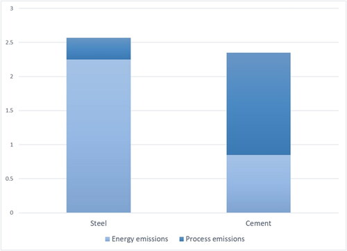
Reducing the embodied carbon of reinforced concrete will, therefore, imply a reduction in these main constituents that have high emission factors. Alternatives to either partially or fully replace either the cement or steel reinforcement should not compromise the structural requirements of the structural system.
Over the years, the use of steel fibres in the construction industry has become prevalent. From tunnelling to foundations and floor systems, steel fibres present many advantages when added to a concrete matrix (Ng & Htut, Citation2017; Officine Maccaferri S.p.A, Citation2010). Various studies on the structural performance of SFRC have shown its post-failure performance, crack-bridging effect and enhanced ductility and flexural toughness (Balendran et al., Citation2002; G. Chen et al., Citation2021; Zhong et al., Citation2021). Steel fibres can also improve the tensile strength, deflection or strain and energy absorption capacities of concrete (Hoang & Tue, Citation2018). Steel fibre has been identified to enhance concrete properties, including improvement in structural strength, reduction in required steel reinforcement and increase in post-crack strength (residual flexural strength) of the concrete element. Yadav and Prashanth (Citation2022) analysed the behaviour of steel fibre-reinforced concrete (SFRC) beams with varying steel fibre content and for different crack widths using a numerical approach and modelling. In their study, they concluded that the ultimate load capacity of a concrete beam reinforced with steel fibres increases with increasing fibre content and decreasing crack length. Mahmood et al. (Citation2018) also investigated the flexural performance of full-scale continuous reinforced concrete beams with and without steel fibres. Their experimental study showed that with a steel fibre dosage of 30 kg/m3 and 60 kg/m3, the load-carrying capacity of the beams increased by 14% and 23%, respectively, and with a reduction in crack spacing. The addition of steel fibres increased the ductility and moment-resisting capacity of the concrete beams as compared to the conventionally reinforced beams. The crack bridging effect of steel fibres in concrete, due to its expansive action, contributes to an increase in the crack resistance and a reduction of internal stresses in the tension area of the concrete (B. Wang & Huang, Citation2008). This property of steel fibres in concrete increases with the steel fibre content and also the strength of the concrete matrix. The concrete-fibre bond in the matrix is a vital factor in the strength and crack propagation of the concrete member (Xu et al., Citation2006).
Transverse reinforcement (stirrups) is provided in concrete beams to resist shear forces and control crack widths and distribution. Both inputs from the concrete material and the stirrups contribute to the overall shear strength of a reinforced concrete member. Placing transverse reinforcement in a concrete beam can be time-consuming and labour-intensive compared to placing longitudinal reinforcement. Much research has been conducted on using alternative materials to replace these stirrups partially or entirely, and the use of steel fibre has proven to be promising. The use of steel fibres in concrete structures can increase its shear strength and can be used as an alternative to replacing the minimum shear reinforcement requirement in the structure entirely (Birincioglu et al., Citation2022; Zamri et al., Citation2021). Steel fibres can improve the residual strength of concrete and reduce the shear crack width by allowing a progressive development of the cracks with increasing applied load (Bhosale & Prakash, Citation2020; Dong et al., Citation2022; Yang et al., Citation2019).
Hussain et al. (Citation2020) compared the mechanical properties of concrete containing various types of fibres and their effect on the concrete thickness in pavement design. In their study, they concluded that steel fibres improve the flexural strength of concrete by about 51–56% in both standard and high-strength concrete and also reduce the overall design thickness of the concrete member by up to 35%. Undoubtedly, such a material has the potential to reduce the material requirements of reinforced concrete and possibly reduce the carbon footprint of concrete.
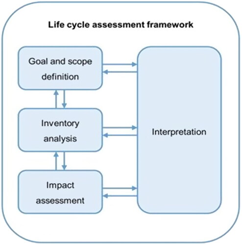
Life cycle assessment (LCA) can be considered a decision-making tool that helps designers select the right and best technology that is environmentally friendly without compromising on the primary requirements of the system. A life cycle assessment follows a fundamental framework (). In the construction industry, all materials and processes are analysed using guidelines from standards such as ISO 14067 (Citation2018), the Greenhouse Gas Protocol (GHG Protocol, Citation2011), PAS 2050 (Publicly Available Specification, 2011) and the European Standards ((EN 15804, Citation2019; EN 15978, Citation2012). The most commonly used standard, the ISO 14000 series, outlines the four main phases of a LCA.
Figure 2. Phases of a life cycle assessment. Adapted from ISO 14040 (Citation2006b) and ISO 14044 (Citation2006c).
In performing a LCA where the material is being compared to another material, a common ground on which the materials will be assessed must be established. The LCA framework relates this to the functional unit for the analysis. Nakic (Citation2018) analysed the environmental performance of concrete with sewage sludge ash and compared it to ordinary concrete using a functional unit of 1 m3 of ready-mixed concrete. Colangelo et al. (Citation2018) also assessed the environmental performance of concrete containing various wastes as a substitute for the aggregates and binders using a functional unit of 1 m3 of concrete. Dossche et al. (Citation2018), in their study on the life cycle of structural beam-floor systems, also adapted a square metre of the system as the functional unit. Most LCA of concrete use a mass/volume-based functional unit (FU), which does not consider the primary performance of the concrete or the substitute material. Using the physical or geometric properties as a reference value in evaluating concrete mixes with alternate materials may not always be the best choice. For instance, in analysing the carbon footprint of a concrete beam with conventional rebars and another with an alternative reinforcing material, using a mass-based functional unit may not be the best choice as this does not reflect the primary function of the intended alternative reinforcing material, such as improving tensile strength or reducing crack formation.
This study analyses the embodied carbon and quantifies the carbon emissions of steel fibre-reinforced concrete using a functional unit that considers the primary function of a reinforcing material in concrete through a LCA methodology that includes the benefits or load after the end of life (EoL). This study will contribute further by linking together the material performance, structural design and environmental performance of SFRC.
2. Materials and methods
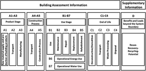
ISO 14040 (Citation2006b) and ISO 14044 (Citation2006c) are the most used international standards for assessing the environmental impacts of a product. These standards provide the framework and specific guidelines for performing LCA. There is a growing need to use whole life cycle assessment to assess the carbon emissions of concrete from design, construction and operational use through to the disposal stage of the structure. The EN 15804 (Citation2019) requires that all construction materials and products must declare modules A1–A3 (Product stage), A4 (transport to the site), A5 (construction/installation), C1–C4 (End of life stage) and module D (Benefits and loads beyond the system boundary) (). Various guidelines have been published to assist in quantifying the carbon emissions of structures (Gibbons & Orr, Citation2020; Royal Institution of Chartered Surveyors [RICS], Citation2017). This study involved two main parts, ie the structural design and analysis and performing the LCA of the various beams.
Figure 3. LCA modules of construction products adapted from EN 15804 (Citation2019).
2.1. Structural design and analysis
2.1.1. Finite element modelling
The modelling of beams, particularly those reinforced with steel fibres, is crucial in understanding their structural performance and environmental impact. Steel fibre-reinforced concrete beams offer significant advantages over traditional reinforced concrete beams, including enhanced tensile strength, ductility and crack resistance. These benefits could potentially lead to more efficient use of materials and improved sustainability in construction. The study evaluates the structural performance and carbon emissions of SFRC beams in comparison to conventional RC beams. To potentially lower the embodied carbon of the concrete elements, the study sought to reduce the amount of traditional steel reinforcing necessary by integrating steel fibres. The goal of creating environmentally friendly building techniques and materials that maintain structural integrity without sacrificing performance is more broadly supported by this strategy. For this study, a finite element analysis (FEA) was performed for the design of both the RC and FRC members, and this was done using SCIA Engineer (Dlouhý & Pouillon, Citation2019). Known for its extensive capabilities, SCIA Engineer is a structural analysis software with built-in design tools and a multi-material library for designing all kinds of structures with support to open Building Information Modelling (BIM). SCIA was chosen for this research due to its ability to allow the selection of design codes, define service life requirements and the availability of the steel fibres (Dramix 5D) that were considered for this study in its material library. It features advanced tools for finite element analysis, dynamic and seismic analysis and integrated design, which streamline the entire workflow from initial concept to detailed design and documentation. The analysis and design of the beams for this study were performed based on design codes and guidelines from Eurocode (EN 1992, Citation2004), German guidelines on steel fibres (Deutscher Ausschuss fur Stahlbeton [DafStb], 2012), Fib Model 10 (Walraven & Horst, Citation2013) and RILEM (Vandewalle et al., Citation2003). 72 number of supported beams were modelled. The SFRC beams were designed to have both steel fibres and conventional steel rebars as reinforcing material. This hybrid approach is aimed at maximising the benefits of each material, combining the tensile strength and crack-bridging capabilities of steel fibres with the established performance of steel rebars. A steel fibre dosage of 20–40 kg/m3 was used for the design of the SFRC beams and these were compared to the control conventional RC beams of the same concrete compressive strength (fck) and span. The beams were designed to have a minimum moment capacity of 50 kN.m, 100 kN.m, 150 kN.m and 200 kN.m. RC beams were subjected to varying loads to ensure a maximum crack width of less than 0.3 mm. This limitation is crucial for maintaining the durability and serviceability of concrete structures. The same loading conditions were applied to the SFRC beams, adjusting the fibre dosage and design parameters (such as area of steel and depth) to achieve a maximum crack width equal to or lower than that of the corresponding RC beam.
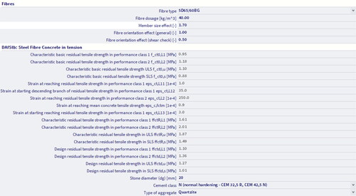
The numerical analysis was conducted using SCIA engineer, which simulated the load-bearing capacity, crack formation and overall structural performance of both RC and SFRC beams. The finite element model included detailed meshing and material properties to ensure accurate simulation results. The material library enables the selection of the type of steel fibres, dosage and cement type, as well as defining the aggregate type and size ().
Figure 4. Defining SFRC material properties for beam modelling.
The depth of both the RC and SFRC beams was determined using the span (L)/effective depth (d) ratio as specified in the Eurocode ((EN 1992, Citation2004). The L/d ratio was used to establish a preliminary design depth, h. For a typical simply supported beam, the preliminary depth (dprelim) is given by
(1)
(1)
The design depth is adjusted accordingly to ensure deflections and crack widths are within allowable limits. The adjustments are based on the initial results run to meet all design requirements, and this involved either increasing the fibre dosage or increasing the depth for additional flexural strength. and show the properties of the various beams used for this study. The beams are identified under the beam ID column in the format ‘Type of reinforcement (RC/SFRC) and concrete compressive strength- Span- Moment capacity’.
Table 1. Properties of modelled RC beams.
Table 2. Properties of modelled SFRC beams.
The material specification for the materials used for the analysis is described below.
Concrete: For the concrete mixes, a 42.5 N cement grade was used for both RC and SFRC. Quartzite aggregate with a maximum stone diameter (dg) of 20 mm was also selected for all concrete mixes as it can withstand high impact force as compared to other aggregates such as limestone and also improve the fracture energy of the concrete (Mousavi & Ranjbar, Citation2021; Tufail et al., Citation2017). Sand was used as the fine aggregate. and show the mechanical properties of the various concrete grades used for the FE analysis of the RC mixes. These properties were obtained from the material library of the FEA software. The SFRC mixes are labelled in the format ‘compressive strength-fibre type and aspect ratio/length-form of delivery’, as shown in . To achieve the required compressive strength, the BRE mix design approach was used to design the base concrete mixes (Teychenné et al., Citation1997). The SFRC mixes were also made using existing experimental data from various studies and compared with the base mix (Gao et al., Citation2023; Guler & Akbulut, Citation2022; Hyun-Ho & Hwa-Jin, Citation2004; Li et al., Citation2022). The same base mix was not used for the SFRC elements as the addition of steel fibres in concrete also potentially enhances the compressive strength of concrete (Guler et al., Citation2019; Jhatial et al., Citation2018; Sivapriya et al., Citation2018).
Table 3. Properties of traditional concrete.
Table 4. Properties of steel fibre-reinforced concrete.
Steel rebars: The standard B500 C steel bars were used as reinforcement in both the RC and SFRC beams with varying diameters to achieve the required minimum design moment. The mechanical properties of the bar are shown in .
Table 5. Properties of steel bars (B500 C).
Steel fibres: Dramix steel fibres were used to design the SFCR members. The properties specified in the materials library of SCIA engineer were used for the verification of results. The material library is open source; hence, new steel fibre materials can be created, and their properties can be modified based on experimental data. The 5D steel fibres were used for all the SFRC beams. The glued bright 5D steel fibres were chosen for this study due to their uniquely shaped hook end, mechanical properties and high tensile strength and ductility (Abdallah et al., Citation2018; Gao et al., Citation2021). and show the geometric and mechanical properties of the steel fibres used.
Figure 5. The geometry of 5D steel fibres. Adapted from Abdallah et al. (Citation2016).
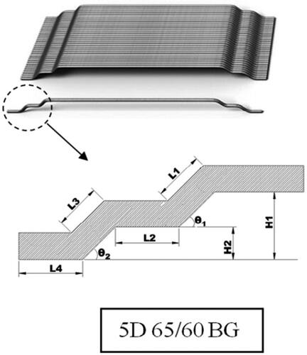
Table 6. Mechanical and geometric Properties of steel fibres (DRAMIX 5D).
2.1.1.1. Moment of resistance (mrd)
A total of 72 RC and SFRC beams were designed to resist a minimum mid-span moment of 50 kN.m, 100 kN.m, 150 kN.m and 200 kN.m. The RC beams were designed in accordance with EN 1992 (Citation2004), and the SFRC beams were also designed using both DafStb (2012) and parts of EN 1992 (Citation2004). The RC beams were used as the control for the design of the SFRC beams. The SFRC beams were designed to achieve the minimum actual moment of the designed RC beams. The verification of the beams was based on ultimate limit state (ULS) checks (capacity check and shear check) and serviceability limit state (SLS) check (crack width check). The load cases considered permanent loads (LC1) and variable loads (LC2). The imposed loads on the beams were selected to represent category A as specified in the Eurocode (EN 1992, Citation2002). The load case combinations used for the analysis were based on the Eurocode. Under the ULS, nine different load combinations were considered, while two load combinations were also considered under the SLS in the analysis. The ULS combination used applied a partial factor of safety, γG and γQ, to the permanent and live loads, respectively, and for the SLS combinations, a factor for quasi-permanent values of variable loads was applied.
The analysis of the SFRC beams was performed on the material and structural element characteristics level as this considers the fibre type, dosage, member size and orientation in accordance with DafStb (2012) and RILEM (Vandewalle et al., Citation2003). The mean residual strength values are determined from beam tests and are used to determine the characteristic residual flexural strength ffcflk,L1 and ffcflk,L2 (Dlouhý & Pouillon, Citation2019; Vandewalle et al., Citation2003). Subsequently, these basic characteristic residual strength values are used to derive the characteristic residual tensile strength values for different limit states. The characteristic residual tensile strength values for ULS, ffct0,u and SLS, ffct0,s, are calculated as shown in EquationEquations (4)(4)
(4) and Equation(5)
(5)
(5) . Additionally, the characteristic residual tensile strength values are determined at specific Crack Mouth Opening Displacement (CMOD), notably ffct0,L1 at CMOD = 0.5 mm and ffct0,L2 at CMOD = 3.5 mm as shown in EquationEquations (2)
(2)
(2) and Equation(3)
(3)
(3) . The characteristic residual tensile strength values are determined by multiplying the basic characteristic residual flexural strength values by a beta factor (βL1, βL2, βu and βs) as specified in DafStb (2012) and as shown in EquationEquations (2)–(5).
(2)
(2)
(3)
(3)
(4)
(4)
(5)
(5)
On the structural level, the effects of the fibre orientation (kfF = 1.0) and member size (kfG = 1.7) are factored to achieve the residual tensile strengths of the SFRC, as shown in EquationEquations (6)–(9).
(6)
(6)
(7)
(7)
(8)
(8)
(9)
(9)
Where ffctR,L1 is the factored residual tensile strength at CMOD = 0.5
ffctR,L2 is the factored residual tensile strength at CMOD = 3.5
ffctR,u is the factored residual tensile strength at ULS
ffctR,s is the factored residual tensile strength at SLS
The design values used for the final analysis are obtained by applying a reduction factor (αfc = 0.85) for long-term effect and a partial factor of safety (γfct = 1.25)
(10)
(10)
(11)
(11)
(12)
(12)
(13)
(13)
Where ffctd,L1 is the design residual tensile strength at CMOD = 0.5
ffctd,L2 is the design residual tensile strength at CMOD = 3.5
ffctd,u is the design residual tensile strength at ULS
ffctd,s is the design residual tensile strength at SLS
For capacity checks and dosage design, SCIA performs an iterative calculation in each finite element (FE) of the beam by a combination of the normal forces and bending moment to achieve equilibrium. The effect of conventional reinforcement is also taken into account in the calculation.
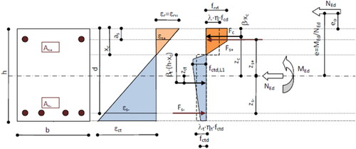
From the stress-strain block diagram (), the following equations of static equilibrium are used.
(14)
(14)
(15)
(15)
Figure 6. Stress-strain distribution block in the cross-section. Adapted from Dlouhý and Pouillon (Citation2019).
The shear capacity of the SFRC beams (VfRd,c) is calculated by adding the effects of steel fibres on the shear capacity (VRd,cf) to that of the cross-section shear capacity of the member considered as concrete without fibres (VRd,c), thus,
(16)
(16)
(17)
(17)
2.1.1.2. Service life design
The design of the control beams (RC beams) was done based on design principles and guidelines from EN 1992 (Citation2004). An XC3 exposure class was selected for the analysis to represent a moderate humidity environment. A design life greater than 100 years was chosen for this analysis as this will reduce the energy requirements and emissions for repairs and replacement during the operational phase of the structure. The durability issue of concrete structures is influenced by factors such as environmental conditions, the concrete cover and the quality of concrete material. Corrosion of steel bars is influenced by the presence of cracks since the effectiveness of concrete covers is reduced by cracks, which act as channels for the ingress of substances causing steel corrosion (AL-Ameeri et al., Citation2021; Lopez-Calvo et al., Citation2018; Sun et al., Citation2020). The crack width is a contributing factor to the depth of carbonation in a concrete structure (Carević & Ignjatović, Citation2019; Guo et al., Citation2022).
Using the crack width as the basis of comparison for SLS checks, load cases were created for all the RC beams, and a design life greater than 100 years was specified. The concrete cover of the beams is in conformance with the British national annexe of the Eurocode for durability and a working life of at least 100 years. Considering the exposure class (XC3) and the design life, a minimum cover of 40 mm is required. Typically, an additional margin (5–10 mm) is added to the minimum cover to account for the extended design life; hence, a minimum concrete cover of 45 mm was specified for the RC beams. The RC beams were loaded, and their maximum crack width was recorded. The SFRC beams were designed to have a minimum of the achieved crack width with the same applied load as that of the RC beams. For the design and analysis of the SFRC beams, a reduced concrete cover was used to assess its impact on the crack width as various studies have proven the crack bridging property of steel fibre-reinforced concrete and reduce the time of ingression to the rebar zone (Granju & Ullah Balouch, Citation2005; Joshi et al., Citation2018; Sun et al., Citation2020; Q. Wang et al., Citation2017; Zeng et al., Citation2020). García-Taengua et al. (Citation2014) proposed an equation for determining the minimum cover/rebar diameter ratio enough to prevent the splitting failure of SFRC, and this was based on the Model Code (Walraven and Horst Citation2013). was used in predicting the concrete cover of the SFRC beams where Cf is the fibre content, and ∇f is the fibre geometry determined from EquationEquation (18)(18)
(18) ;
(18)
(18)
Figure 7. Minimum C/D to compressive strength of concrete (García-Taengua et al., Citation2014).
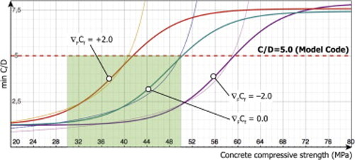
Where λf and Ɩf are the fibre slenderness and length, respectively. Based on this model and the extended design life, a minimum concrete cover of 35 mm was used for the SFRC beams.
The model emphasises the interplay between fibre content and geometry, which are pivotal in mitigating splitting failures. The recommended cover ensures an adequate bond between the concrete and reinforcement, which is required for maintaining the structural performance of SFRC beams under varying loading conditions. Adhering to this minimal cover specification reduces the risk of premature failure due to fibre-induced splitting, hence extending the structure’s service life.
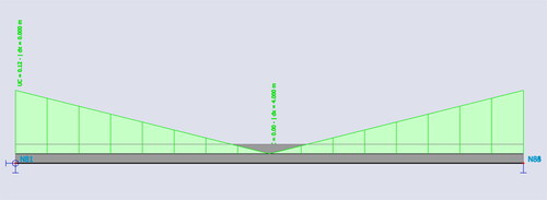
The SLS design of all the beams was in accordance with EN 1992 (Citation2004) and considered mainly the crack width and stress limitation checks of the compressive and tensile stresses in concrete and reinforcement, respectively. and show the displacement of an SFRC and an RC beam designed to accommodate a minimum moment capacity of 50 kN.m. The performance of the SFRC beams was compared to that of the conventional RC beams to ensure that their maximum displacement is lesser or equal to that of the RC beams. For instance, in and , the maximum displacement that was achieved for the RC beam designed to accommodate a minimum moment capacity after loading was 6.4 mm, and that of the SFRC designed to accommodate the same moment capacity was 4.3 mm. The comparison also included their shear capacity, ensuring that the SLS checks were also met, especially given that previous research has shown the potential of steel fibres to reduce the transverse reinforcement requirements in beams ().
Figure 8. Displacement of simply supported RC beam under a loading condition in SCIA engineer.
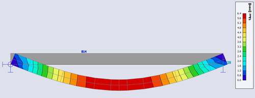
Figure 9. Displacement of SFRC beams under a given loading condition in SCIA engineer.
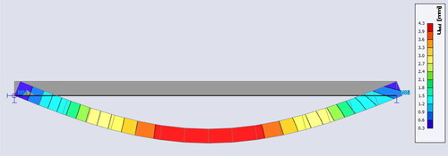
Figure 10. Shear force analysis of SFRC beam in SCIA engineer.
2.2. Life cycle analysis of RC and SFRC beams
2.2.1. Goal and scope definition
This study aims to quantify the carbon emissions of SFRC beams using the general framework and guidelines from ISO 14040 (Citation2006b) and ISO 14044 (Citation2006c). A cradle-to-gate with options, modules C1–C4 and module D approach, was adopted as defined in EN 15804 (Citation2019).
To understand the material and environmental performance of SFRC, conventional RC beams were compared to the SFRC beams, which were designed to have the exact structural requirements. Using concrete strength, span and moment capacity as variables, the carbon footprint of using steel fibres to partially replace conventional reinforcement (steel rebars) was assessed using a whole-life carbon assessment approach by RICS (Citation2017) and Gibbons and Orr (Citation2020).
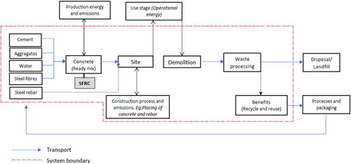
Performing a life cycle assessment of a product such as concrete could be very complex if no scope and boundaries are defined, as there are a lot of inflows and outflows, which, if not monitored, could result in double counting and affect the assessment. The system boundary for this study is summarised in and . In the production of steel fibre-reinforced concrete, the steel fibres are added at the concrete plant during production before it is transported to the site, while with conventional concrete, the reinforcing material (steel rebars) is added on-site, as shown in and . The system boundary also includes the production of the concrete mix using cement, sand, crushed aggregate, water and superplasticiser. The extraction processes, such as mining and transportation to the plant of these raw materials, are not elaborated as the data used for this study factored in all these processes. The operational requirements, maintenance and repair are outside the system boundary as there is not enough numerical data on the operational performance of steel fibre-reinforced concrete during its use stage. It is also worth mentioning that processes for transporting goods to landfills and beyond were not considered in this study.
Figure 11. LCA system boundary for conventionally reinforced concrete.
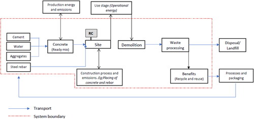
Figure 12. LCA system boundary for steel fibre-reinforced concrete.
2.2.1.1. Functional unit
The ISO 14040 series defines a functional unit as a measure for the quantification of the intended use and function provided by a product (ISO 14040, Citation2006b). The selection of a suitable functional unit for assessing two materials meant to have similar performance is very vital in performing a LCA (Purnell, Citation2013; Van den Heede & De Belie, Citation2012). For this study, the two materials being compared (conventionally reinforced concrete and steel fibre-reinforced concrete) were analysed based on their primary and common function. Since the focus of this study is mainly on the reinforcing materials of the concrete members, a functional unit that considers the primary function of reinforcement in concrete was considered; therefore, the comparison was not on 1 m3 of conventional RC to 1 m3 of SFRC. The comparison of the RC and SFRC beams for this study was based on the total amount of reinforced concrete of a beam required per unit span to resist a unit bending moment with a design life greater than 100 years. Reinforcing materials are added to concrete primarily to improve its tensile strength; hence, this functional unit was selected to consider both the properties of the reinforcing materials under consideration and the durability or service life requirements.
2.2.2. Inventory analysis
The life cycle inventory (LCI) data were taken mainly from the Inventory of Carbon and Energy (ICE) database (Jones, Citation2019), the Greenhouse Gas Reporting: conversion factors 2022 (Department for Business, Energy & Industrial Strategy [BEIS], 2022) and various environmental product declarations (EPD). The environmental product declarations used for both steel rebars and steel fibres were based on EN 15804 (Citation2019) and verified in accordance with ISO 14025 (Citation2006a), as this increases the correctness of the data involved in the assessments. The geographical area for most of the types of data used in Europe and, in a few cases, global average data were used. The LCI data is summarised in .
Table 7. Life cycle inventory data summary.
2.2.2.1. Product stage (module A1–A3)
The product stage of an LCA involves all activities, from the extraction of raw material to transportation to the manufacturing plant and the manufacturing process. As shown in , the data collected for the production stage for this research considers all of these activities and focuses mainly on the material emissions for the analysis. An environmental product declaration (EDP) reports the greenhouse gas emissions of a product in kgCO2e. Various independently verified EPDs were used for the analysis of this study. Data for the greenhouse gas emissions of the reinforcing materials, steel rebars and steel fibres were taken from Liberty Speciality Steel (Speciality Steel Citation2021) and Bekaert (Citation2021), respectively. shows the embodied carbon of the various raw materials used in this study. The EPDs from the various steel rebars and steel fibres consider data from materials and energy (electricity, fuel, thermal) associated with their production.
Table 8. Embodied carbon of construction materials.
Raw materials are delivered to the concrete production plant for concrete production. At the concrete plant, other additives, such as superplasticisers, are added during the production process. A typical average UK cement, which consists of 86.1% clinker, 0.04% ground granulated blast-furnace slag (GGBS), 3.4% fly ash, 4.8% gypsum, 5.1% limestone and 0.56% minor additional constituent was used for the study. This data included all emissions associated with the production of cement (Jones, Citation2019). The concrete used for the study was considered to be ready-mix concrete and not in situ. For the production of SFRC, the steel fibres are added at the production stage of the concrete before the mix is transported to the site. The concrete mixes used were designed using the BRE mix design method () and experimental mixes from literature to obtain the desired compressive strength for the analysis (Gao et al., Citation2023; Hyun-Ho & Hwa-Jin, Citation2004; Li et al., Citation2022; Paluri et al., Citation2020; Teychenné et al., Citation1997). Superplasticiser and a lower water-cement ratio were used where necessary to achieve a high compressive strength for the mixes and improve workability.
Table 9. Base mix proportion for 30 MPa, 40 MPa and 50 MPa grade concrete.
To determine the total carbon emissions at the product stage, the quantities of material required to produce a mix for both the FRC and RC beams were multiplied by their embodied carbon factor (ECF), as shown in EquationEquation (19)(19)
(19) . EquationEquation (19)
(19)
(19) gives the basic calculation used for the product stage (A1–A3).
(19)
(19)
Where TECA1–A3 = Total embodied carbon at product stage, (kgCO2e)
= Embodied carbon factor of kth material from raw material extraction to manufacturing, (kgCO2e/kg)
= Quantity of concrete constituent, (kg)
K = Concrete constituent/raw material
2.2.2.2. Transportation to site and construction process (module A4–A5)
After production at the concrete plant, the concrete is delivered to the construction site using a rigid type vehicle weighing more than 17 t (concrete mixing vehicle). The transportation of the steel rebars was also considered using an articulated type vehicle (>33 t). The travel distance is assumed to be 50 km from the production site to the construction site based on assumptions and recommendations from the IstructE (Gibbons & Orr, Citation2020). The construction of a typical beam on site involves mainly the placement of the rebars before pouring the concrete into the formwork, after which vibration and finishing take place where applicable. This part of the process involves labour and small machinery. In determining the energy consumption of the construction workers, the average calories burnt by construction workers based on gender and type of construction activity was assumed to be 224.1 calories/h for a male worker (Liu & Gambatese, Citation2018). With an assumed body surface area of 1.5695 m2, the metabolic rate of a construction worker involved in rebar work is about 2.1267 kcal/min. m2 (Jiang et al., Citation2018). In a 7-h continuous operation and an assumed idle time of 15%, the total energy consumed will be 4.98 MJ. Using a conversion rate of 3.6 MJ per kWh, the placement of a cubic metre of reinforced concrete in 0.045 kgCO2e/m3 of reinforced concrete. The emission from the labour requirement was added to the plant requirement for placing the reinforced concrete to determine the total emissions on the site.
The total embodied carbon at the construction stage included the emissions of transporting the ready-mix concrete and the steel rebars to the site, the emissions from the plant used for placing the concrete and steel rebars and the emissions from the construction activities to carry out these works as shown in EquationEquation (20)(20)
(20) .
(20)
(20)
Where TECA4–A5 = Total carbon emission for transport of concrete to site and installation, (kgCO2e)
= Mode of Transport emission factor for kth material (kgCO2e/kg/km)
dk = Transport distance of kth material to the site, (km)
= Emission factor for the operation of site plant/equipment, (kgCO2e/m3)
= volume of concrete, (m3)
= Emission factor for construction activities (kgCO2e/man-days)
t = Duration of construction activity (man-days)
2.2.2.3. End of life (module C1–C4)
The end-of-life (EoL) scenario considers modules C1–C4, ie demolition, transport, waste processing and disposal. The data for these modules were taken from the EPD of the steel rebar and steel fibres used, as well as data on plant operations. With a lack of data on the energy requirements for demolishing SFRC members, the operation of demolishing (equipment required) for both SFRC and RC was assumed to be the same, as both members were designed to have the same strength. However, the time and size of the members were factored into the demolishing process to reflect the impact of the material on the overall result, as the demolishing of SFRC will require more energy input than RC. The average CO2 emission from the demolition of a structure at the end of its service life is about 0.007 kgCO2/kg of the concrete mass (Sizirici et al., Citation2021). The transport of the construction and demolition waste (CDW) to the waste processing site is assumed to be 50 km from the construction site for both scenarios. For this analysis, it is assumed that a 100% recovery is made for both SFRC and RC beams. An estimated value of 0.013 kgCO2e/kg of waste is assumed for the waste processing and disposal of the concrete element of both SFRC and RC (Gibbons & Orr, Citation2020). Data for the waste processing and disposal of the steel fibres and rebar elements were taken from verified EPD data in accordance with EN 15804 (Bekaert, Citation2021; Speciality Steel, Citation2021).
The scenario for this study involves the processing and disposal of the demolished waste at an offsite CDW processing plant. The CDW is screened to separate the rebar from the concrete before it is crushed using a crusher. For the SFRC waste, a crusher with a magnetic separator is used to separate the steel fibres from the crushed concrete further. The recovered components from the waste, ie concrete, rebar and steel fibres, are recycled. A fraction of the elements not recovered for reuse/recycling are disposed of in a landfill. shows the recovery rate for the various components that were used for analysing the end-of-life phase of this study.
Table 10. End-of-life scenario for the various elements.
The approach to determining the total carbon emission at the EoL stage is similar to the product stage. As shown in EquationEquation (21)(21)
(21) , the calculation involves the emissions associated with the plant used for the demolishing of the beam, transporting the CDW to the waste processing site and the waste processes to segregate the CDW into various elements for recycling and disposal.
(21)
(21)
Where TECC1–C4 = Total embodied carbon associated with the EoL, (kgCO2e)
= Emission factor for waste processing and disposal of kth material, (kgCO2e/kg)
= Quantity of reinforced concrete material (kg)
= Emissions associated with the demolishing activities (kgCO2e/kg)
= Transport emission factor for transporting CDW to the waste processing site (kgCO2e/kg/km)
d = Distance to waste processing site, (km)
2.2.2.4. Benefits and loads beyond system boundary (module D)
This section of the LCA considers the potential of the recovered elements from the CDW by downcycling. The concrete element can be recycled to be used as aggregate for concrete mixes for both non-structural and low-strength structural concrete and various civil works such as road base and fill (Putri, Citation2017; Kim, Citation2022; Strieder et al., Citation2022; B. Wang et al., Citation2021). The production of crushed concrete aggregates has an estimated global warming potential (GWP) of (-)0.0002 ∼ 0.0177 kgCO2/kg (Integrated Materials Solutions, Citation2020; Lei et al., Citation2022) ('-'denotes a benefit), and this is considered a benefit in this module for this study as the use of recycled aggregate will put no energy or carbon emission on the production of another concrete mix. Conventional steel rebars cannot be reused at their end-of-life but can be recycled to produce steel of the same or different quality depending on the metallurgy and processing method used. Since steel scrap has a significant value, efforts are undertaken to recycle it rather than dispose of it. Scrap benefits have a GWP of about (-) 0.264 kgCO2/kg (Speciality Steel, Citation2021). The steel fibres recovered can be reused for new steel production using an electric arc furnace (EAF) process. The recycling of steel fibres has a GWP of about (-)0.236 kgCO2/kg and this is considered a benefit to other production systems and therefore a reduction of the GWP of this study (Bekaert, Citation2021).
The approach to determining the benefit of the concrete material is also similar to the product stage as this also involves multiplying the quantity of the recovered material by the emission factor associated with recycling the recovered material, as shown in EquationEquation (22)(22)
(22) .
(22)
(22)
Where TECD = Total embodied carbon at module D, (kgCO2e)
= Embodied carbon factor of recycling/reuse of kth material, (kgCO2e/kg)
= Quantity of kth concrete constituent, (kg)
2.2.3. Life cycle impact assessment
The environmental impacts of concrete buildings can be associated with indicators such as climate change, acidification potential, photochemical-oxidant creation, eutrophication and many others. The climate change impact category was chosen for the impact assessment of the RC and SFRC beams.
Using the results from the various modules (A–D), the whole life embodied carbon (WLEC) of the RC and the SFRC beams can be calculated using EquationEquation (23)(23)
(23) .
(23)
(23)
The results obtained were normalised with respect to the chosen functional unit to assist in making a fair comparison of both the RC and SFRC beams. The actual moments of the beams were used for the normalisation process.
3. Results and discussion
The use of steel fibres in concrete beams significantly enhances their load-bearing capacity. This enhancement is particularly noticeable in the beams’ ability to withstand tensile stresses and dynamic loads, which are critical factors in structural performance. These improvements in the SFRC beams’ structural performance affect their environmental performance as well. presents the WLEC of the various beams expressed in kgCO2e/kN.m/m. From the results obtained, the carbon footprint of the SFRC beams is much lower than that of the RC beams. On average, the embodied carbon of the RC beams was estimated to be about 0.439 kgCO2e/kN.m/m, and that of the SFRC was about 0.273 kgCO2e/kN.m/m. These results show that the addition of steel fibres in concrete beams can potentially reduce the GWP by about 37%. This finding is consistent with that of E. Chen et al. (Citation2023), who also concluded that the annual GWP of RC edge beams containing steel fibres was 33–60% lower than that of the conventional RC beams. The product stage (A1–A3) and the EoL (C1–C4) are the main contributors to the embodied carbon of the structure. The study also confirms that the embodied carbon of concrete increases with increasing concrete compressive strength. This was expected as; generally, cement content increases with increasing compressive strength.
Table 11. WLEC of RC and SFRC beams.
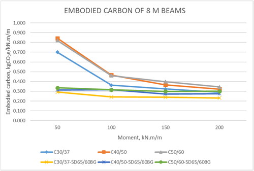
The results, as shown in , show that the embodied carbon of all the beams generally reduces with increasing moment capacity. It can, therefore, be inferred that for a given span and compressive strength, the embodied carbon of concrete decreases with the increasing moment capacity of the concrete beam, as shown in , and that designing for higher moment capacity is an eco-friendly approach. This result may be explained by the fact that the tensile strength of a reinforced concrete member is influenced mainly by the reinforcing material, hence designing a structural section by making efficient use of the reinforcing material’s capability rather than the compressive property approach such as increasing the adequate depth, which will, in turn, increase the concrete volume and cement content can reduce the embodied carbon of the concrete.
Figure 13. Embodied carbon of 4 m span RC and SFRC beams.
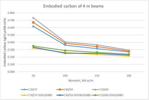
Figure 14. Embodied carbon of 6 m span RC and SFRC beams.
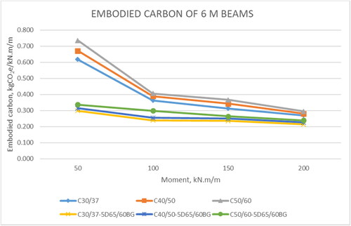
Figure 15. Embodied carbon of 8 m span RC and SFRC beams.
There was a significant reduction in the material components of the concrete with the addition of steel fibres. The design depth of the beams was reduced when steel fibres were added to the concrete mix. With steel fibre content of 20 kg/m3–40 kg/m3, an average design depth reduction of 17% was achieved, with a maximum reduction of 32% achieved in the SFRC30-4-50 and SFRC40-4-50 beams designed to resist a 50 kN.m moment.
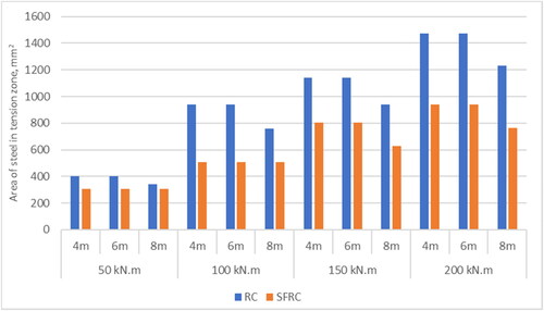
The design and analysis of the beams also showed a reduction in the area of steel provided in the various sections. The addition of steel fibres of dosages between 20 kg/m3–40 kg/m3 showed a reduction of the area of steel provided (As, prov) by 29.8%–36.2% in the tension area of the beam elements to achieve the minimum resistances (). Consistent with findings from various studies (Birincioglu et al., Citation2022; Dang et al., Citation2021; Torres & Lantsoght, Citation2019), the steel fibres significantly improved the shear capacity of the beams, and this also contributed to the reduction in the minimum transverse reinforcement required for the beams.
Figure 16. Area of steel provided in the tension zone of 30 MPa RC and SFRC beams.
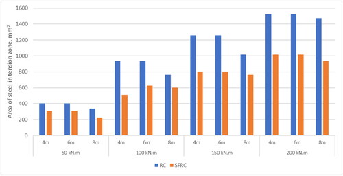
Figure 17. Area of steel provided in the tension zone of 40 MPa RC and SFRC beams.
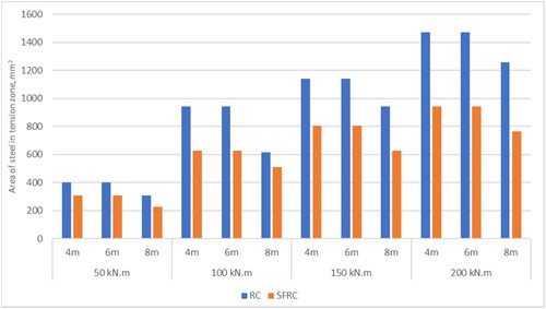
Figure 18. Area of steel provided in the tension zone of 50 MPa RC and SFRC beams.
4. Conclusion
This paper investigated the embodied carbon of SFRC beams using a functional unit that factors in both the mechanical and durability properties of the material. The moment capacity and crack resistance of the concrete beams were used to evaluate the structural and service life performance of the beams. A cradle-to-gate with options, modules C1–C4 and module D LCA assessment, was performed to compare the embodied carbon of conventional RC beams and SFRC beams. The main conclusions are presented below.
The average embodied carbon of SFRC beams is about 0.273 kgCO2e/kN.m/m, which is about 37% lower than that of the conventional RC beams. This can be attributed mainly to improved residual strength and the material-saving properties of the steel fibres. The material-saving effect is primarily contributed to by the reduced amount of concrete in the reinforced member, hence reducing the overall embodied carbon of the structure.
The addition of steel fibres as reinforcement in an RC beam can reduce the average design depth by 17%, and this is dependent on the structural requirements (span and loading) and the fibre dosage.
Steel fibres can reduce the area of steel required in the tension zone of a RC beam by about 36% due to its high residual tensile strength, and this was achieved by adding a steel fibre content greater than 30 kg/m3.
The results indicate that SFRC beams with higher moment capacities generally have lower carbon emissions per unit of moment capacity. This is because the enhanced structural efficiency of SFRC beams allows for a reduction in material use, thereby decreasing the embodied carbon; hence, designing tension members with lower compressive strength but with higher strength/grade of reinforcement is carbon-friendly.
In the life cycle of a concrete structure, the product and the end-of-life stages produce most of the greenhouse gas (GHG) emissions if the usage phase is disregarded.
Further research on the thermal performance (heat absorption and conductivity) of SFRC members is required to determine their performance during the use phase and assess the impact of SFRC on the operation energy.
Authors’ contributions
GOA: methodology, investigation, formal analysis, writing- original draft, review and editing
SB: conceptualisation, validation, supervision, resources
KA: validation, supervision, writing- review and editing
BM: data review, validation, supervision, writing- review and editing.
Sample results verification.docx
Download MS Word (391.5 KB)Acknowledgements
The authors would like to express gratitude to the University of Portsmouth and the Ghana Scholarship Secretariat for the support provided for this study.
Disclosure statement
No potential conflict of interest was reported by the author(s).
Data availability statement
The data that support the findings of this study are available upon reasonable request. All inquiries regarding the data used for this study should be directed to the corresponding author, Gideon Osei Asare.
Additional information
Funding
Notes on contributors
Gideon Osei Asare
Gideon Osei Asare is currently a lecturer and also a PhD candidate at the University of Portsmouth. He holds a BSc and MSc with over 6 years industry experience as a structural engineer. His research interests are in Low carbon concrete, Fibre reinforced concrete, Structural analysis and design and Construction Management.
Stephanie Barnett
Stephanie Barnett is currently the Head of School of Civil Engineering and Surveying at the University of Portsmouth. She holds a BSc and PhD and with over 10 years rSurveying at the University of Portsmouth. She holds a degree and a PhD in physics/ chemistry and with over 10 years research experience in cement chemistry and concrete technology. Her research interests include, High performance concrete, Durability issues of concrete, Fibre reinforced concrete, Low carbon concrete, Cement chemistry and Materials characterisation.
Kenneth Awinda
Kenneth Awinda is a Chartered Civil Engineer with over 10 years in industry as an engineer and project manager for major consultants and contractors. He is a Senior Lecturer in the School of Civil Engineering and Surveying at the University of Portsmouth. He holds a BSc, MSc and PhD. His current research interests are in Modelling the behaviour of high performance fibre reinforced concrete, construction materials and in construction engineering and management.
Brett Martinson
Brett Martinson is a Senior Lecturer at the School of Civil Engineering and Surveying and a member of the Environmental Technology Research Group at the University of Portsmouth. He holds a B.Eng/ M.Eng, MSc and PhD. His research interests are in Water conservation, augmentation and reuse in buildings, Building physics, On-site water supply in low-income countries and Technology adoption in low-income countries.
References
- Abdallah, S., Fan, M., & Rees, D. W. A. (2016). Analysis and modelling of mechanical anchorage of 4D/5D hooked end steel fibres. Materials & Design, 112, 539–552. https://doi.org/10.1016/j.matdes.2016.09.107
- Abdallah, S., Rees, D. W. A., Ghaffar, S. H., & Fan, M. (2018). Understanding the effects of hooked-end steel fibre geometry on the uniaxial tensile behaviour of self-compacting concrete. Construction and Building Materials, 178, 484–494. https://doi.org/10.1016/j.conbuildmat.2018.05.191
- Al-Ameeri, A. S., Rafiq, M. I., & Tsioulou, O. (2021). Combined impact of carbonation and crack width on the chloride penetration and corrosion resistance of concrete structures. Cement and Concrete Composites, 115, 103819. https://doi.org/10.1016/j.cemconcomp.2020.103819
- Balendran, R. V., Zhou, F. P., Nadeem, A., & Leung, A. Y. T. (2002). Influence of steel fibres on strength and ductility of normal and lightweight high strength concrete. Building and Environment, 37(12), 1361–1367. https://doi.org/10.1016/S0360-1323(01)00109-3
- Bekaert. (2021). Environmental product declaration type III ITB No. 215/2021. https://www.bekaert.com/en/product-catalog/construction/concrete-reinforcement/downloads
- Bhosale, A. B., & Prakash, S. S. (2020). Crack propagation analysis of synthetic vs. steel vs. hybrid fibre-reinforced concrete beams using digital image correlation technique. International Journal of Concrete Structures and Materials, 14(1), 57. https://doi.org/10.1186/s40069-020-00427-8
- Birincioglu, M. I., Keskin, R. S. O., & Arslan, G. (2022). Shear strength of steel fiber reinforced concrete deep beams without stirrups. Advances in Concrete Construction, 13(1), 1–10. https://doi.org/10.12989/acc.2022.13.1.001
- Carević, V., & Ignjatović, I. (2019). Influence of loading cracks on the carbonation resistance of RC elements. Construction and Building Materials, 227, 116583. https://doi.org/10.1016/j.conbuildmat.2019.07.309
- Chen, E., Berrocal, C. G., Löfgren, I., & Lundgren, K. (2023). Comparison of the service life, life-cycle costs and assessment of hybrid and traditional reinforced concrete through a case study of bridge edge beams in Sweden. Structure and Infrastructure Engineering, 19(1), 39–57. https://doi.org/10.1080/15732479.2021.1919720
- Chen, G., Gao, D., Zhu, H., Song Yuan, J., Xiao, X., & Wang, W. (2021). Effects of novel multiple hooked-end steel fibres on flexural tensile behaviour of notched concrete beams with various strength grades. Structures, 33, 3644–3654. https://doi.org/10.1016/j.istruc.2021.06.016
- Colangelo, F., Forcina, A., Farina, I., & Petrillo, A. (2018). Life cycle assessment (LCA) of different kinds of concrete containing waste for sustainable construction. Buildings, 8(5), 70. https://doi.org/10.3390/buildings8050070
- Dang, T. D., Tran, D. T., Nguyen-Minh, L., & Nassif, A. Y. (2021). Shear resistant capacity of steel fibres reinforced concrete deep beams: An experimental investigation and a new prediction model. Structures, 33, 2284–2300. https://doi.org/10.1016/j.istruc.2021.05.091
- Department for Business, Energy & Industrial Strategy. (2022). Greenhouse gas reporting: Conversion factors 2022. https://www.gov.uk/government/publications/greenhouse-gas-reporting-conversion-factors-2022
- Deutscher Ausschuss fur Stahlbeton. (2012). DAfStb guideline’ steel fibre reinforced concrete’. https://ec.europa.eu/growth/tools-databases/tris/sl/index.cfm/search/?trisaction=search.detail&year=2012&num=681&dLang=EN
- Dlouhý, L., & Pouillon, S. (2019). Application of the design code for steel fibre reinforced concrete into finite element software. IOP Conference Series: Materials Science and Engineering, 596(1), 012009. https://doi.org/10.1088/1757-899X/596/1/012009
- Dong, S., Wang, D., Wang, X., D'Alessandro, A., Ding, S., Han, B., & Ou, J. (2022). Optimising flexural cracking process of ultra-high performance concrete via incorporating microscale steel wires. Cement and Concrete Composites, 134, 104830. https://doi.org/10.1016/j.cemconcomp.2022.104830
- Dossche, C., Boel, V., & De Corte, W. (2018). Comparative material-based life cycle analysis of structural beam-floor systems. Journal of Cleaner Production, 194, 327–341. https://doi.org/10.1016/j.jclepro.2018.05.062
- EN 1992. (2002). Loading for buildings. Part 1. BSI.
- EN 1992. (2004). Eurocode 2: Design of concrete structures. BSI.
- EN 15804. (2019). BS EN 15804:2012 + A2:2019. Sustainability of construction works – Environmental product declarations – Core rules for the product category of construction products. BSI. https://www.en-standard.eu/bs-en-15804-2012-a2-2019-sustainability-of-construction-works-environmental-product-declarations-core-rules-for-the-product-category-of-construction-products/
- EN 15978. (2012). BS EN 15978:2011 Sustainability of construction works. Assessment of environmental performance of buildings. Calculation method. BSI. https://www.en-standard.eu/bs-en-15978-2011-sustainability-of-construction-works-assessment-of-environmental-performance-of-buildings-calculation-method/
- Gao, D., Ding, C., Pang, Y., & Chen, G. (2021). An inverse analysis method for multi-linear tensile stress-crack opening relationship of 3D/4D/5D steel fiber reinforced concrete. Construction and Building Materials, 309, 125074. https://doi.org/10.1016/j.conbuildmat.2021.125074
- Gao, D., Guo, Y., Pang, Y., Chen, G., Shi, M., Ding, C., & Liu, D. (2023). Analysis and prediction of the compressive and splitting tensile performances for the novel multiple hooked-end steel fiber reinforced concrete. Structural Concrete, 24(1), 1452–1470. https://doi.org/10.1002/suco.202200487
- García-Taengua, E., Martí-Vargas, J. R., & Serna, P. (2014). Splitting of concrete cover in steel fiber reinforced concrete: Semi-empirical modelling and minimum confinement requirements. Construction and Building Materials, 66, 743–751. https://doi.org/10.1016/j.conbuildmat.2014.06.020
- GHG Protocol. (2011). The greenhouse gas protocol. https://ghgprotocol.org/product-standard
- Gibbons, O., & Orr, J. (2020). How to calculate embodied carbon. The Institution of Structural Engineers. https://www.istructe.org/IStructE/media/Public/Resources/istructe-how-to-calculate-embodied-carbon.pdf
- Gibbs, M. J., Soyka, P., & Conneely, D. (2000). IPCC good practice guidance and uncertainty management in national greenhouse gas inventories. IPCC. https://www.ipcc.ch/publication/good-practice-guidance-and-uncertainty-management-in-national-greenhouse-gas-inventories/
- Granju, J.-L., & Ullah Balouch, S. (2005). Corrosion of steel fibre reinforced concrete from the cracks. Cement and Concrete Research, 35(3), 572–577. https://doi.org/10.1016/j.cemconres.2004.06.032
- Guler, S., & Akbulut, Z. F. (2022). Residual strength and toughness properties of 3D, 4D and 5D steel fibre-reinforced concrete exposed to high temperatures. Construction and Building Materials, 327, 126945. https://doi.org/10.1016/j.conbuildmat.2022.126945
- Guler, S., Yavuz, D., Korkut, F., & Ashour, A. (2019). Strength prediction models for steel, synthetic, and hybrid fiber reinforced concretes. Structural Concrete, 20(1), 428–445. https://doi.org/10.1002/suco.201800088
- Guo, Q., Jiang, L., Wang, J., & Liu, J. (2022). Analysis of carbonation behavior of cracked concrete. Materials, 15(13), 4518. https://doi.org/10.3390/ma15134518
- Hoang, K. H., & Tue, N. V. (2018). Comparative flexural and tensile behaviours of ultra-high performance fibre reinforced concrete with different steel fibres. In V. Mechtcherine, V. Slowik, & P. Kabele (Eds.), Strain-hardening cement-based composites (pp. 492–501). Springer. https://doi.org/10.1007/978-94-024-1194-2_57
- Hussain, I., Ali, B., Akhtar, T., Jameel, M. S., & Raza, S. S. (2020). Comparison of mechanical properties of concrete and design thickness of pavement with different types of fiber-reinforcements (steel, glass, and polypropylene). Case Studies in Construction Materials, 13, e00429. https://doi.org/10.1016/j.cscm.2020.e00429
- Hyun-Ho, L., & Hwa-Jin, L. (2004). Characteristic strength and deformation of SFRC considering steel fiber factor and volume fraction. Journal of the Korea Concrete Institute, 16(6), 759–766. https://doi.org/10.4334/JKCI.2004.16.6.759
- Integrated Materials Solutions. (2020). Environmental product declaration EPD no: 1205. https://www.igbc.ie/wp-content/uploads/2020/06/EPD-IMS-Recycled-Aggregates-18.06.2020-EPDIE-20-22.pdf
- International Energy Agency. (2019). Direct CO2 emissions from selected heavy industry sectors, 2019 – charts – data & statistics. https://www.iea.org/data-and-statistics/charts/direct-co2-emissions-from-selected-heavy-industry-sectors-2019
- International Energy Agency. (2020). Iron and steel technology roadmap. https://www.iea.org/reports/iron-and-steel-technology-roadmap
- International Energy Agency. (2022a). Cement. https://www.iea.org/reports/cement
- International Energy Agency. (2022b). Global energy review: CO2 emissions in 2021. https://www.iea.org/reports/global-energy-review-co2-emissions-in-2021-2
- ISO 14025. (2006a). ISO 14025:2006. Environmental labels and declarations—Type III environmental declarations—Principles and procedures (1st ed.). ISO. https://www.iso.org/standard/38131.html
- ISO 14040. (2006b). ISO 14040: Environmental management-life cycle assessment-principles and framework. https://www.iso.org/standard/37456.html
- ISO 14044. (2006c). ISO 14044: 2006 Environmental management-life cycle assessment-requirements and guidelines (1st ed., Vol. 14044). https://www.iso.org/obp/ui/#iso:std:iso:14044:ed-1:v1:en
- ISO 14067. (2018). ISO 14067: Greenhouse gases—Carbon footprint of products—Requirements and guidelines for quantification (1st ed.). https://www.iso.org/cms/render/live/en/sites/isoorg/contents/data/standard/07/12/71206.html
- Jhatial, A. A., Sohu, S., Bhatti, N.-K., Lakhiar, M. T., & Oad, R. (2018). Effect of steel fibres on the compressive and flexural strength of concrete. International Journal of Advanced and Applied Sciences, 5(10), 16–21. https://doi.org/10.21833/ijaas.2018.10.003
- Jiang, B., Li, H. X., Dong, L., Wang, Y., & Tao, Y. (2018). Cradle-to-site carbon emissions assessment of prefabricated rebar cages for high-rise buildings in China. Sustainability, 11(1), 42. https://doi.org/10.3390/su11010042
- Jones, C. (2019). Embodied carbon-The ICE database. Inventory of Carbon and Energy (ICE).
- Joshi, S. S., Thammishetti, N., Prakash, S. S., & Jain, S. (2018). Cracking and ductility analysis of steel fiber-reinforced prestressed concrete beams in flexure. ACI Structural Journal, 115(6), 1575–1588. https://doi.org/10.14359/51706827
- Kim, J. (2022). Influence of quality of recycled aggregates on the mechanical properties of recycled aggregate concretes: An overview. Construction and Building Materials, 328, 127071. https://doi.org/10.1016/j.conbuildmat.2022.127071
- Lei, B., Yu, L., Chen, Z., Yang, W., Deng, C., & Tang, Z. (2022). Carbon emission evaluation of recycled fine aggregate concrete based on life cycle assessment. Sustainability, 14(21), 14448. https://doi.org/10.3390/su142114448
- Li, Y., Zhang, Q., Kamiński, P., Deifalla, A. F., Sufian, M., Dyczko, A., Kahla, N. B., & Atig, M. (2022). Compressive strength of steel fiber-reinforced concrete employing supervised machine learning techniques. Materials, 15(12), 4209. https://doi.org/10.3390/ma15124209
- Lippiatt, N., Ling, T.-C., & Pan, S.-Y. (2020). Towards carbon-neutral construction materials: Carbonation of cement-based materials and the future perspective. Journal of Building Engineering, 28, 101062. https://doi.org/10.1016/j.jobe.2019.101062
- Liu, D., & Gambatese, J. (2018, March 29). Energy consumption by construction workers for on-site activities [Paper presentation]. Construction Research Congress 2018 (pp. 533–542), New Orleans, LA, United States. https://doi.org/10.1061/9780784481301.053
- Lopez-Calvo, H. Z., Montes-García, P., Jiménez-Quero, V. G., Gómez-Barranco, H., Bremner, T. W., & Thomas, M. D. A. (2018). Influence of crack width, cover depth and concrete quality on corrosion of steel in HPC containing corrosion inhibiting admixtures and fly ash. Cement and Concrete Composites, 88, 200–210. https://doi.org/10.1016/j.cemconcomp.2018.01.016
- Mahmood, S. M. F., Agarwal, A., Foster, S. J., & Valipour, H. (2018). Flexural performance of steel fibre reinforced concrete beams designed for moment redistribution. Engineering Structures, 177, 695–706. https://doi.org/10.1016/j.engstruct.2018.10.007
- Mousavi, S. M., & Ranjbar, M. M. (2021). Experimental study of the effect of silica fume and coarse aggregate type on the fracture characteristics of high-strength concrete. Engineering Fracture Mechanics, 258, 108094. https://doi.org/10.1016/j.engfracmech.2021.108094
- Nakic, D. (2018). Environmental evaluation of concrete with sewage sludge ash based on LCA. Sustainable Production and Consumption, 16, 193–201. https://doi.org/10.1016/j.spc.2018.08.003
- Ng, T. S., & Htut, T. N. S. (2017). Structural application of steel fibres reinforced concrete with and without conventional reinforcement. New Zeal. Concr. Ind, 3101(2006).
- Officine Maccaferri S.p.A. (2010). New line 9 metro construction (case history INT/CH/TL 001 OM).
- Paluri, Y., Mogili, S., Mudavath, H., & Pancharathi, R. K. (2020). A study on the influence of steel fibres on the performance of Fine Reclaimed Asphalt Pavement (FRAP) in pavement quality concrete. Materials Today: Proceedings, 32, 657–662. https://doi.org/10.1016/j.matpr.2020.03.147
- Publicly Available Specification. (2011). PAS 2050: Specification for the assessment of the life cycle greenhouse gas emissions of goods and services. BSI. https://knowledge.bsigroup.com/products/specification-for-the-assessment-of-the-life-cycle-greenhouse-gas-emissions-of-goods-and-services/standard
- Purnell, P. (2013). The carbon footprint of reinforced concrete. Advances in Cement Research, 25(6), 362–368. https://doi.org/10.1680/adcr.13.00013
- Putri, A. D. (2017). Recycled concrete aggregate (RCA) for the use in construction: General review. Advance Concrete Materials, School of Civil Engineering, Beijing Jiaotong University, 1–14.
- Royal Institution of Chartered Surveyors. (2017). Whole life carbon assessment for the built environment.
- Sivapriya, S. V., Ridhuvaran, S., Karthick, V., & Gopikrishna, R. (2018). Flexural and compressional behaviour of steel fiber reinforced concrete. Dusunen Adam, 9, 405–412.
- Sizirici, B., Fseha, Y., Cho, C.-S., Yildiz, I., & Byon, Y.-J. (2021). A review of carbon footprint reduction in the construction industry, from design to operation. Materials, 14(20), 6094. https://doi.org/10.3390/ma14206094
- Speciality Steel. (2021). Environmental product declaration (BREG EN EPD No.: 000341). UK CARES. https://www.carescertification.com/files/approvals/1758/sustainability/1738.pdf
- Strieder, H. L., Dutra, V. F. P., Graeff, Â. G., Núñez, W. P., & Merten, F. R. M. (2022). Performance evaluation of pervious concrete pavements with recycled concrete aggregate. Construction and Building Materials, 315, 125384. https://doi.org/10.1016/j.conbuildmal.2021.125384
- Sun, B., Xiao, R., Ruan, W., & Wang, P. (2020). Corrosion-induced cracking fragility of RC bridge with improved concrete carbonation and steel reinforcement corrosion models. Engineering Structures, 208, 110313. https://doi.org/10.1016/j.engstruct.2020.110313
- Teychenné, D. C., Erntroy, H. C., Marsh, B. K., Establishment, B. R., & Franklin, R. E. (1997). Design of normal concrete mixes (2nd ed.). Building Research Establishment. http://prism.librarymanagementcloud.co.uk/port/items/833185
- Torres, J. A., & Lantsoght, E. O. L. (2019). Influence of fiber content on shear capacity of steel fiber-reinforced concrete beams. Fibers, 7(12), 102. https://doi.org/10.3390/fib7120102
- Tufail, M., Shahzada, K., Gencturk, B., & Wei, J. (2017). Effect of elevated temperature on mechanical properties of limestone, quartzite and granite concrete. International Journal of Concrete Structures and Materials, 11(1), 17–28. https://doi.org/10.1007/s40069-016-0175-2
- United Nations Environment Programme. (2022). 2022 Global status report for buildings and construction: Towards a zero‑emission, efficient and resilient buildings and construction sector. http://www.unep.org/resources/publication/2022-global-status-report-buildings-and-construction
- Van den Heede, P., & De Belie, N. (2012). Environmental impact and life cycle assessment (LCA) of traditional and 'green’ concretes: Literature review and theoretical calculations. Cement and Concrete Composites, 34(4), 431–442. https://doi.org/10.1016/j.cemconcomp.2012.01.004
- Vandewalle, L., Nemegeer, D., Balázs, G., Barr, B., Barros, J., Bartos, P., Banthia, N., Criswell, M., Denarie, E., Prisco, M., Falkner, H., Gettu, R., Gopalaratnam, V., Groth, P., Hausler, V., Kooiman, A., Kovler, K., Massicotte, B., Mindess, S., & Walraven, J. (2003). Test and design methods for steel fibre reinforced concrete’ - sigma-epsilon-design method - Final recommendation. Materials and Structures, 36, 560–567.
- Walraven, J. C., & Horst, A. V. D. (2013). FIB model code for concrete structures 2010. Internation Federation for Structural Concrete (fib). https://research.tudelft.nl/en/publications/fib-model-code-for-concrete-structures-2010
- Wang, B., & Huang, C. (2008). Study on crack resistance of steel fiber reinforced self-stressing concrete in old bridge reinforcement. Key Engineering Materials, 400-402, 543–548. https://doi.org/10.4028/www.scientific.net/KEM.400-402.543
- Wang, B., Yan, L., Fu, Q., & Kasal, B. (2021). A comprehensive review on recycled aggregate and recycled aggregate concrete. Resources, Conservation and Recycling, 171, 105565. https://doi.org/10.1016/j.resconrec.2021.105565
- Wang, Q., Sun, W., Guo, L., Gu, C., & Zong, J. (2017). Prediction of chloride ingress in steel fibre reinforced concrete under bending load. Ceramics - Silikaty, 62, 59–66. https://doi.org/10.13168/cs.2017.0045
- Xu, Z., Wenyin, W. Y., & Liang, Y. (2006). Experimental study of steel fibre bridging action on crack propagation in fibre reinforced concrete. In M. H. Aliabadi, Q. Li, L. Li, & F. G. Buchholz (Eds.), Fracture and damage mechanics V, pts 1 and 2 (Vols. 324–325, pp.1067–1067+). Trans Tech Publications Ltd. https://doi.org/10.4028/www.scientific.net/KEM.324-325.1067
- Yadav, D., & Prashanth, M. H. (2022). Numerical study on the behaviour of steel fiber reinforced concrete beams for different crack lengths. Materials Today: Proceedings, 65, 1459–1466. https://doi.org/10.1016/j.matpr.2022.04.410
- Yang, Y., Wang, Y., Chen, Y., & Zhang, B. (2019). Test study on the impact resistance of steel fiber reinforced full lightweight concrete beams. Earthquakes and Structures, 17(6), 567–575. https://doi.org/10.12989/eas.2019.17.6.567
- Zabalza Bribián, I., Valero Capilla, A., & Aranda Usón, A. (2011). Life cycle assessment of building materials: Comparative analysis of energy and environmental impacts and evaluation of the eco-efficiency improvement potential. Building and Environment, 46(5), 1133–1140. https://doi.org/10.1016/j.buildenv.2010.12.002
- Zamri, N. F., Mohamed, R. N., & Elliott, K. S. (2021). Shear capacity of precast half-joint beams with steel fibre-reinforced self-compacting concrete. Construction and Building Materials, 272, 121813. https://doi.org/10.1016/j.conbuildmat.2020.121813
- Zeng, W., Ding, Y., Zhang, Y., & Dehn, F. (2020). Effect of steel fibre on the crack permeability evolution and crack surface topography of concrete subjected to freeze-thaw damage. Cement and Concrete Research, 138, 106230. https://doi.org/10.1016/j.cemconres.2020.106230
- Zhong, A., Sofi, M., Lumantarna, E., Zhou, Z., & Mendis, P. (2021). Flexural capacity prediction model for steel fibre-reinforced concrete beams. International Journal of Concrete Structures and Materials, 15(1), 28. https://doi.org/10.1186/s40069-021-00461-0