
 ?Mathematical formulae have been encoded as MathML and are displayed in this HTML version using MathJax in order to improve their display. Uncheck the box to turn MathJax off. This feature requires Javascript. Click on a formula to zoom.
ABSTRACT
In the last decades, most investigations in titanium bone implantology have applied lattice structures instead of dense materials to reduce weight and obtain the mechanical properties similar to human bones. However, there is still a need for more research on the optimal design of lattice titanium implants with proper mechanical behaviour and heat treatment investigations, which directly affects the mechanical, microstructural, and morphological characteristics. The present study aims to examine the effect of densities and unit cell sizes for Selective Laser Melting (SLM)-printed lattice structures created by MSLattice. TPMS lattice structures including Diamond, Gyroid, and Primitive generated by MSLattice software were subsequently printed using Ti-6Al-4 V ELI. Tensile testing of DTi (dense) produced an ultimate tensile strength of 1241.58 ± 23.92 MPa and a Yield strength of 1151 ± 8.6 MPa, while its compression test resulted in an ultimate value of 1424.8 ± 20.13 MPa. The increase in density from 20% to 30% has resulted in a doubling of some mechanical properties. The lattice structure of the Gyroid at 30% density presented a UCS value of 143.96 ± 0.89 MPa as the highest, while that of the Diamond at 20% density presented the lowest with 46.89 ± 0.43 MPa. The values for energy absorption and plateau stress follow in a precise sequence.
1. Introduction
For many years, bone implants have been utilised to address bone defects and disorders. In the past decades, Additive Manufacturing has made it feasible to create customised and intricate implants closely matching a patient’s anatomy [Citation1]. Among all materials, Titanium and its alloys have outstanding biocompatibility, corrosion resistance, and a high strength-to-weight ratio, making them the preferred biomaterials for implants compared to other biomaterials such as stainless steel and Co-based alloys [Citation1,Citation2]. Furthermore, titanium alloys have also shown beneficial physiochemical properties. Titanium forms a protective layer that provides biocompatibility and corrosion resistance with an almost negligible corrosion rate in a physiological milieu [Citation2]. It should be noted that numerous biomaterials, such as ceramics and polymers, are used to implant medical devices. However, the problem is that they are either excessively brittle or fail to provide the appropriate strength for load-bearing applications [Citation3].
The most common applications for the Ti–6Al–4 V, with Grades 5 and 23, are in the biomedical field. The elastic modulus of these dense alloys is 113 GPa [Citation4]. In contrast, the elastic modulus of human bone is 1.5 GPa for the trabecular bone and 30 GPa for the cortical bone [Citation5,Citation6]. However, applying a lattice structure offers an advantageous combination of strength and weight. The interconnected lattice pattern distributes loads more evenly across the implant, mimicking the mechanical properties of natural bone. This feature reduces stress concentrations and the risk of implant failure due to excessive forces. For instance, in the paper of Suresh et al. [Citation7], the Elastic modulus of the dense and lattice parts was reported to be 120 GPa and 80 GPa, respectively.
A lattice structure is an ideal choice for designing to obtain mechanical properties like human bones. Nevertheless, lattice structures promote osseointegration compared to solid implants, which is when the bone grows into and integrates with the implant. The porous nature of lattice structures allows for improved nutrient and oxygen flow, facilitating the infiltration of bone cells into the implant. This results in better bone ingrowth and long-term stability of the implant. It should be noted that incorporating a porous structure allows the implant to be lighter and use less material without compromising its integrity. This reduces manufacturing costs and makes the implant more biocompatible and less likely to cause adverse reactions. At some point, lattice implants could simplify the surgical procedure by providing improved visibility and accessibility during implant placement. Surgeons can use instruments like screws, wires, or sutures to secure the implant, taking advantage of the lattice’s interconnected structure.
It has been observed that triply periodic minimal surfaces (TPMS) have gained significant attention as base geometries for designing lattice structures [Citation8]. Based on the literature review on Ti-6Al-4 V lattice structures, the Diamond structure has displayed the best overall performance in terms of energy absorption, porosity, and stiffness, which are similar to those of human bones [Citation9–14]. For this structure, an 80% porosity is recommended [Citation15,Citation16]. Owing to its high stiffness and porosity, the gyroid structure appears to be a great fit when it comes to load-bearing bone replacement [Citation4]. On another hand, due to superior mechanical properties (high elastic modulus and yield strength), primitive lattice structure fits well the need of the pore structure of the tibia [Citation14]. Thereafter, all three lattice structures can be considered well suited for designing lattice implants.
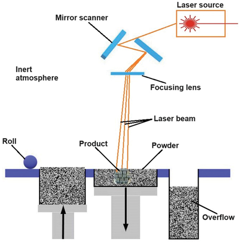
During the last decade, there has been a growing interest in developing lattice titanium bone implants that can be produced via the Selective Laser Melting (SLM) process [Citation7–14]. The effects of different process parameters such as laser power, scanning speed, and powder size on the mechanical properties of these implants have been the focus of several recent studies. The results of these studies state that increased laser power and reduced scanning speed may cause higher densities and improved mechanical properties [Citation16,Citation17]. The process concept of SLM can be seen in . The selective laser melting (SLM) technique involves the use of a high-powered laser that melts and fuses titanium powder particles layer-by-layer to create the desired lattice structure. This process is controlled by a computer-aided design (CAD) model that ensures precise control over the final shape and dimensions of the implant. The implant lattice structure facilitates load distribution which in turn promotes a structural-functional connection between the implant and living bone [Citation6]. The SLM process also enables the fabrication of highly porous (lattice structure) implants, which can enhance cell growth and formation processes, leading to faster healing times [Citation14,Citation15]. However, this process is still highly economically impractical and will take some time to become famous worldwide [Citation18,Citation19].
Figure 1. Working principle of selective laser melting (SLM) technique.
There is potential for the selective laser melting (SLM) process to create intricate lattice structures; however, there have been limited studies conducted on the biocompatible Ti6Al4V alloy. A recently observed software, MSLattice by O. Al-Ketan [Citation20], was employed in this study to generate TPMS lattice structures. Usually, where the study deals with porosity to model or generate a lattice structure, MSLattice generates the structure using density. Very few studies have been conducted using this software, which allows one to study phenomena density, not porosity. Therefore, this study aimed to evaluate the mechanical properties of dense and porous Ti–6Al–4 V ELI generated by MS Lattice that were directly manufactured using Ti–6Al–4 V powder through SLM. The tensile, compression, and hardness tests were assessed at ambient temperature. This research provided the foundation for following biomedical investigations, such as the development of porous implants.
2. Methodology
This section covers powder characterisation, the design and manufacturing processes for the chosen material, mechanical analysis, and characterisation for printed and tested Ti-6AL-4 V alloys.
2.1. Powder characterization
Dense-printed Ti-6Al-4 V ELI and lattice-printed Ti-6Al-4 V ELI, also referred to as DTi and LTi, respectively, were the specimens utilised in this investigation. The powder Ti–6Al–4 V ELI with a grade size of 20–53 µm was acquired from Sino-Euro Materials of Xi’ and Co, Ltd. (Sino-Euro), a Northwest Institute for Non-ferrous Metal Research division. The EDS (energy dispersive spectroscopy) analysis was conducted by scanning electron microscopy (SEM) JEOL JSM-IT200(LA) to identify the chemical composition of the virgin powder and dense structure. A Mastersizer 3000 was used to detect the particle size distribution of the used powder as well. The optical parameters were an absorption coefficient of −1.413 and a refractive index of −2.51.
2.2. Lattice structures
The design of the lattice specimens was implemented using MS Lattice for triply periodic minimal surface (TPMS) structures. A literature review showed that Diamond, Cube, and Primitive lattice structures perform best overall in energy absorption, contain porosity, and stiffness similar to the human bones [Citation2–7]. Therefore, in this proposed research, 20% density along with a unit cell size of 3 mm for the Gyroid structure and 20 and 30% density along with a unit cell size of 5 mm for the Diamond and Primitive structures were utilised (). The decision to use different unit cell sizes (3 mm instead of 5 mm) and a 20% density for the Gyroid structure (also 3 mm instead of 5 mm) was due to the thickness of the structure around the face of the lattice. The edge of that Gyroid structure required a cell size with half of the cells to create a flat surface. If a unit cell size of 5 mm was chosen, the strut size around the surfaces would be less than 1 mm, which could lead to printing failures as the printer requires at least 0.5 mm strut thickness for successful printing of the specimens. To avoid such printing failures, a unit cell sizes of 3 mm and 30% density was utilised for the Gyroid structure. The overall size of the TPMS lattice structures was 15mm × 15mm. illustrates lattice structures that are used in this investigation.
Figure 2. Types of lattice structures that were investigated: (a) Diamond; b) Gyroid; (c) Primitive.
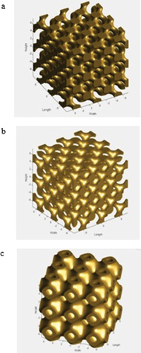
Table 1. The density and size of the lattice structures generated in MS lattice.
2.3. SLM process parameters and manufacturing
The Renishaw AM 400 produced the specimens using the SLM principle. The manufactured samples were chosen to be either porous or dense. Dense samples were later tested for bulk material characterisation. The process parameters were selected as the default of Renishaw suggestions, chosen from the software library for Ti-6Al-4 V. Hence, both dense and lattice samples were manufactured with a laser power of 200 W, scanning speed of 1112 mm/s, hatch spacing of 0.08 mm, and layer thickness of 0.03 mm, as demonstrated in . All printing was done using the reduced build volume (RBV) platform.
Table 2. Process parameters used for SLM printing of Ti-6Al-4 V.
2.4. Lattice structure characterization
The compressive behaviour of lattice structures has been extensively studied and is well-documented. It is notably more straightforward than a tensile test, necessitating a specialised testing setup to prevent potential stress concentration.
Regarding deformation modes under compression, lattice structures are categorised into stretch-dominated and bending-dominated types. The main difference between them is that for stretch-dominated lattice structures, struts deform axially, while for bending-dominated lattice structures, they deform primarily due to bending. Both types of lattice structures exhibit elastic, plastic, and densification regions. Stretch-dominated lattices display fluctuating plastic zones, while bending-dominated lattice structures exhibit weaker but stable plastic zones.
The values of stress (represented by σ) and strain (represented by ε) are determined based on factors such as the force applied by the compression platen on the lattice (F), the initial area of the lattice base (A₀), the amount of deformation (Δ), and the original height of the structure (ℎ₀). These calculations can be expressed as follows:
The energy absorption at a specific strain level could be obtained by integrating the stress–strain curve, starting from zero and extending up to the point of densification strain. Thus, it leads to the following equation:
Efficiency of energy absorption is provided by the following equation:
Where σm is the maximum stress on the stress–strain curve. The efficiency of the bending-dominated lattice structures is higher than that of the stretch-based lattice structures due to the smooth stress-strain profile of the bending-dominated lattices [Citation21].
Plateau stress is calculated by the following equation:
Where is strain when first peak occurs.
2.5. Morphological analysis and crack investigation
After printing, the surface morphology and pore characteristics were examined using scanning electron microscopy (SEM JEOL JSM-IT200(LA)). E-dispersive X-ray spectroscopy (EDS) analysis was applied to determine the elemental composition of the powder and the dense structure. In addition, water abrasive jet machining is used to cut the broken tensile bulks and then the specimen is inserted into the SEM for fractographical investigations. All these procedures were applied to investigate the material surface.
2.6. Mechanical analysis
The tensile and compression tests at ambient temperature were performed using a universal testing machine with a 50 kN load cell. The dense specimens were designed using Solidworks software. Both tests were performed according to ASTM E8M-13a [Citation22].
The specimens, each measuring 10 mm, 15 mm, 20 mm in height, and 6 mm in diameter, underwent compression testing. The main point of using different heights was to observe the size effect. The compression tests were performed at a speed of 5 mm/min on dense and lattice prints. After the compression test, the fractured specimens were analysed using a scanning electron microscope (SEM). Also, the compression tests were conducted on lattice structures () at a 1 mm/min strain rate until the UTS value reached.
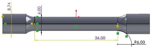
The tensile bulks have a gauge length (G) of 30 mm, a diameter (D) of 6 mm, a radius (R) of 6 mm, and a length of reduced section (A) of 36 mm (). The tensile tests were conducted at a strain rate of 5 mm/min until fracture. After the test, using a SEM, the fractography of the broken specimens was examined.
Figure 3. Tensile test specimen.
The Vickers microhardness was conducted on the specimen with a 0 degree of inclination using the HMV-G Micro-hardness machine. The hardness load was 200 g with a dwell time of 12 seconds. shows the procedure for preparing the material for the hardness testing. The specimen was grounded and polished in advance before testing.
Table 3. Preparation procedure of Ti-6Al-4 V for hardness test.
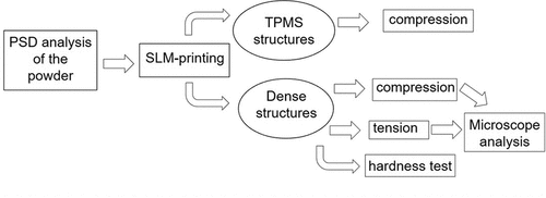
The flow chart of the methodology can be viewed in .
Figure 4. Flow diagram.
3. Results and discussions
This section of the paper discusses the outcomes and observations from the experiments conducted. First, an analysis of the properties of unused Ti-6Al-4 V ELI powder is presented. Then, the analysis centres around the impact of dense and porous materials on mechanical properties and characteristics. Additionally, the fractography is examined after a tension test on the cracked surface.
3.1. Characterization of virgin powder Ti–6Al–4 V ELI
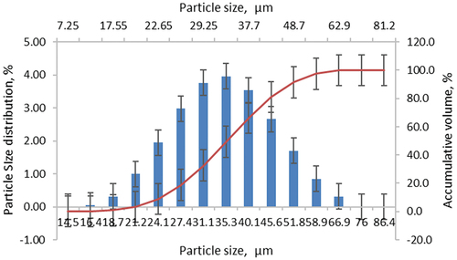
The virgin Ti–6Al–4 V ELI powder’s particle size distribution (PSD) ranged from 20 to 53 μm, and its D10, D50, and D90 values were, respectively, 27.7 μm, 40.4 μm, and 57.9 μm (). A 0.75 span was observed from the PSD. As demonstrated in , the PSD and span indicate that the Ti–6Al–4 V ELI powder is coarse and contains a broad particle size distribution.
Figure 5. Particle size distribution of the virgin Ti-6Al-4V powder.
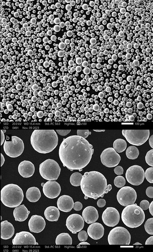
The powder particle morphology exhibits good sphericity, but a small satellite presence is observed (). The figures on the SEM were obtained using the magnification sizes of 100 and 550 times, respectively ().
Figure 6. Powder morphology image of the virgin Ti-6Al-4V powder: (a) Magnifications of x100; (b) Magnifications of x550.
lists the outcomes of the EDS study performed on the virgin Ti-6Al-4 V powder and dense specimen using SEM. The aluminium and vanadium concentrations of the Ti–6Al–4 V ELI powder (5.87 ± 0.02 and 4.17 ± 0.02%) were within the specified range, as indicated by ASTM F136–13 (5.5–6.5% for Al and 3.5–4.5% for V). The same powder was utilised for the production of DTi and LTi.
Table 4. Chemical composition of the virgin Ti–6Al–4 V ELI powder and dense specimen.
3.2. Bulk mechanical properties
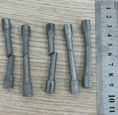
Dense materials compression tests were conducted on cylindrical parts, while tensile tests were on bulk tensile specimens. The printed specimens for compression are illustrated in . The compression was done on the specimens with D = 6 mm and H = 10, 15, and 20 mm, respectively.
Figure 7. SLM printed dense samples for compression.
The first experiment, with the size of D = 6 mm and H = 15 mm, had a lower value of strength in comparison to the second and third experiments, with a difference of around 300–400 MPa. Also, the compression test with the dense specimens with D = 6 mm and H = 20 mm has some marginal differences in the UTS values, as seen in . Nevertheless, after compressing all dense specimens, the size effect shows that the higher the height of the specimen for the compression with the same diameter, the lower the strength value. Regarding size effect, most papers investigate the thickness of specimens, such as strut size, which directly affects mechanical properties. For instance, considering the compression results of the lattice structures (), it has less density and less strength. However, applying the vice-versa methodology demonstrates the same hypothesis. Hence, as the size of a member increases, there is a tendency for its strength to diminish [Citation23]. The illustrations for all tested specimens are presented in .
Figure 8. Compression results of the Ti-6Al-4V samples.
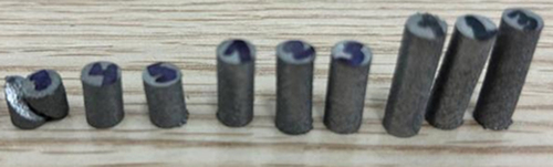
Table 5. Ultimate compression strength results of the dense Ti-al-4 V.
Table 6. Tensile test results of the dense.
represents the compression test results of the dense parts. However, the experimental results revealed that the results for Ti-Al-4 V specimens with a height of 10 mm and a diameter of 6 mm match those found in the literature [Citation24]. Hence, the UCS of the dense Ti-6Al-4 V parts is 1424.8 ± 20.13 MPa.
illustrates the tensile tests of as-built Ti-6Al-4 V samples. Experimental tensile testing results showed ultimate tensile strength of 1241.58 ± 5.97 MPa, while Yield Strength is 1151 ± 5.66 MPa and Elastic Modulus is 116.63 ± 4.35 GPa, as shown in . Comparing the obtained results in this study with existing literature, Suresh et al. [Citation24] reported that tensile samples have a UTS value of 1147 ± 14 MPa and YTS of 1064 ± 17 MPa. It was observed that these values were around 100 MPa less than the results obtained in this experimental work. The difference in the tensile results between this study and the investigation of Suresh et al. [Citation24] is due to different process parameters.
Figure 9. Tensile results of the Ti-6Al-4V samples.
3.3. Lattice mechanical properties
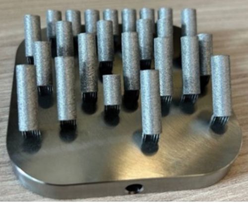
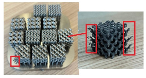
In , SLM-printed lattice structures for compression tests are demonstrated. After printing, Diamond lattice structures had redundant materials at the corners, as can be seen in . If these lattice structures are used for biomedical applications, they should be machined with an electro-discharged machine (EDM) or other equipment to resolve this redundancy in the sides.
Figure 10. SLM printed lattice samples for compression.
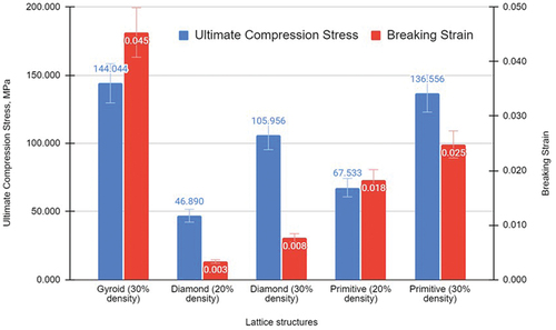
The compression results of the lattice structures state that the mechanical properties of the lattices were below expectation, which is why there is a need for optimal density for the next printing. The human femur bone has a load-bearing capacity of 205 MPa when compressed along its length, as per its mechanical properties for UCS [Citation25]. Future research aims to examine similar lattice structures within a 30–40% density range. This is because, from the obtained results, it is discernable that UCS is doubled when the density increases from 20% to 30% (). From the given table, it is shown that the highest value of the UCS belongs to the Gyroid structure (143.96 ± 0.89 MPa), while the lowest value of the UCS has the Diamond structure with 20% density (46.89 ± 0.43 MPa). The exact sequence is obtained in Yield Strength. However, it has the lowest value of the Elastic Modulus (3.18 ± 1.54 GPa). Moreover, if the UCS and Yield Strength values are compared regarding strength differences for the same lattice structures, Diamond structures with 20% density have almost the same values for both Yield and Ultimate compression strength. This is 46.32 ± 0.38 MPa and 46.89 ± 0.43 MPa of Yield and Ultimate Compression Strength, respectively. The other lattice types have around 5 MPa (Primitive, 20% density), 7 MPa (Diamond, 30% density), 11 MPa (Primitive, 30% density), and 19 MPa (Gyroid, 30% density) of differences in strength value among Yield Strength and UCS. In addition, the highest number of Elastic Modulus is acquired for Diamond structures (13 GPa), continuing in the sequence of Primitive structures (
4 GPa) and Gyroid structures.
Table 7. Compression results of the lattice.
The bar chart in displays various information obtained from the stress–strain curves following the compression of the lattice structures. As can be seen in the chart, the lower value of the strain belongs to the Diamond lattice structures with 20% density for both strain-stress values, while the highest belongs to the Gyroid structure.
Figure 11. Compression results of the lattice structures.
The Vickers microhardness was conducted on the HMV-G Micro-hardness machine on the cross-sectioned specimen with a 0 degree of inclination in the print. The average value of the Ti-6Al-4 V hardness is 381.5 ± 8 HV. The obtained hardness data meets the requirements of the literature. A study on morphology and metallurgical properties of Ti6Al4V stated that the microhardness value for the as-built Ti-6Al-4 V alloy is 390 ± 10 HV [Citation26].
Using the EquationEquations (3(3)
(3) -Equation5
(5)
(5) ), Energy absorption, Energy absorption efficiency, and Plateau stress were obtained and included in . The table demonstrates that the Gyroid structures have good energy absorption (19.79 ± 4.41 MJ/m3) and efficiency (2.05 ± 0.18), as well as Plateau Stress (133.99 ± 9.40 MPa), providing the highest value in comparison to other structures. Hence, considering and , Gyroid structures have better mechanical properties than others. The lowest value of energy absorption and Plateau Stress have the Diamond structure with 20% density, which was the same in case of UCS and Yield Strength.
Table 8. Mechanical characterisations of the compressed lattice.
3.4. Microstructure investigation of the tensile tested dense structures
After conducting the compression and tensile test, the broken specimens underwent analysis using a scanning electron microscope (SEM) to examine their fractography, as shown in and .
Figure 12. Fractography SEM images of compression-fractured specimens with the magnifications of (a, c) x30; (b) x37; (d) x55.
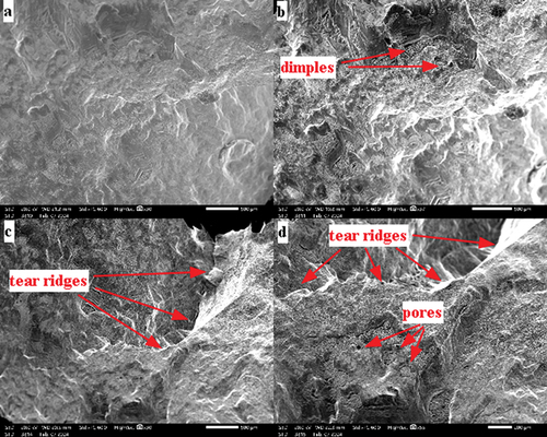
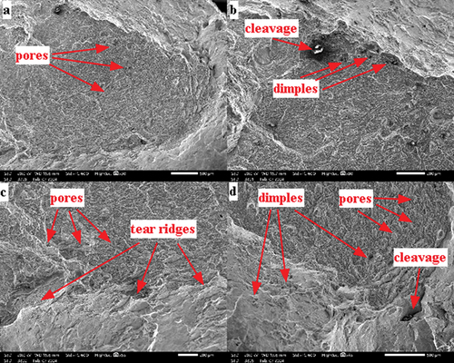
Figure 13. Fractography SEM images of tensile fractured specimens with the magnifications of (a) x30; (b) x80; (c) x55; (d) x45.
The SEM images of the compressed specimens had a small number of dimples, pores, and tear ridges on the crack surface (). Despite observing marginal features on the surface, the overall surface look is smoother. It has fewer features than the surface of the specimens after tensile testing. It indicates that when SLM-printed specimens undergo compression, the forces applied may cause the material to behave ductile, allowing for controlled deformation and a smoother fracture surface. The nature of compression forces tends to compact the material, potentially reducing the occurrence of irregularities or jagged features on the fractured surface [Citation24].
After conducting the tensile test, the broken specimens underwent analysis using a scanning electron microscope (SEM) to examine their fractography, as shown in . The SEM images in revealed various features on the fractured surfaces, providing insights into the materials’ behaviour under stress of tension. The specimens exhibited multiple surface defects such as pores, dimples, tear ridges, and cleavage. These features indicate a mixture of ductile and brittle characteristics in the specimens, as reported in [Citation24]. Notably, the fractography of specimen DTi indicated a brittle nature, aligning with expected ductile traits within the cracks. In the paper of Suresh et al. [Citation24], the specimens had similar features but with a negligible amount of unmelted powder. The trapped and unmelted particles on the side surface result from a lack of vacuuming of the powder after printing or improper cleaning. Additionally, the presence of unmelted powder in the fractured regions indicated possible issues with material consistency [Citation27]. The comprehensive fractography analysis provides valuable insights into the material’s behaviour and quality, highlighting areas for further investigation and improvement in the manufacturing process.
4. Conclusion
In this study, TPMS lattice structures such as Diamond, Gyroid, and Primitive were generated by MS Lattice software and then printed by SLM printer for initial investigation of mechanical properties and characteristics of Ti–6Al–4 V ELI. Also, dense Ti-6Al-4 V specimens were studied for mechanical properties, hardness, and fractography under SEM. The main findings of the experiment are as follows:
The DTi’s tensile test revealed a UTS of 1241.58 ± 23.92 MPa and a YS of 1151 ± 8.6 MPa. On the other hand, its compression test yielded an ultimate value of 1424.8 ± 20.13 MPa. The hardness of DTi in this experiment was 381.5 HV.
Based on the compression of LTi with differences in densities of 20% and 30%, UCS shows that higher densities result in double the mechanical properties. The Gyroid lattice structure with 30% density has the highest UCS value at 143.96 ± 0.89 MPa, while the Diamond lattice structure with 20% density has the lowest UCS value at 46.89 ± 0.43 MPa. The exact sequence is acquired for Energy absorption and Plateau stress values.
The cracked surface of DTi displayed various features such as craters, cup-and-cone fractures, dimples, tear ridges, and cleavage in the fracture pattern after mechanical testing. Additionally, there were un-melted powder particles present in and around the cracks of DTi, visible on both the fractured surface and the adjacent side surface when viewed under SEM.
For future investigation, it is aimed to study the same lattice structures in a range of 30–40% density. Also, for further development, this study needs biomedical response investigations to identify its biomedical applications. Nevertheless, heat treatment and microstructural analysis studies are other experimental work that must be covered.
Nomenclature
| AM | = | Additive Manufacturing |
| EDS | = | Energy Dispersive Spectroscopy |
| SEM | = | Scanning Electron Microscopy |
| SLM | = | Selective Laser Melting |
| TPMS | = | Triply Periodic Minimal Surface |
| F | = | Applied Force |
| A0 | = | Area of the lattice bounding box cross section. |
| = | Traverse Displacement | |
| ℎ0 | = | Initial height of the lattice |
| σ | = | Stress |
| ε | = | Strain |
| = | Relative Density | |
| σy | = | Yield Stress |
| E | = | Elastic Modulus |
| = | Energy Absorption | |
| = | Energy Absorption Efficiency |
Disclosure statement
The authors assert that they do not have any identifiable financial conflicts of interest or personal connections that might be perceived as impacting the research presented in this paper.
Additional information
Funding
References
- Amini AR, Laurencin CT, Nukavarapu SP. Bone tissue engineering: recent advances and challenges. Crit Rev Biomed Eng. 2012;40(5):363–408. doi: 10.1615/critrevbiomedeng.v40.i5.10
- Elsayed M, Ghazy M, Youssef Y, et al. Optimization of SLM process parameters for Ti6Al4V medical implants. Rapid Prototyping J. 2019 Apr;25(3):433–447. doi: 10.1108/rpj-05-2018-0112
- Soro N, Brodie EG, Abdal-Hay A, et al. Addi- tive manufacturing of biomimetic titanium-tantalum lattices for biomedical implant applications. Mater Des. 2022 Jun;218:110688. doi: 10.1016/j.matdes.2022.110688
- Song C, Liu L, Deng Z, et al. Research progress on the design and performance of porous titanium alloy bone implants. J Mater Res And Technol. 2023 Mar;23:2626–2641. doi: 10.1016/j.jmrt.2023.01.155
- Shoujin Z, Qirui W, Jianhua Y. Mechanical properties of 316L stainless steel porous structure formed by selective laser melting. Infrared And Laser Eng. 2020;49(8):75–80. doi: 10.15980/j.tzzz.2020.01.018
- Betteridge O, Hassanin H, El-Sayed MA, et al. Fabrication and optimisation of Ti-6Al-4V lattice- structured total shoulder implants using laser additive manufacturing. Mater. 2022 Apr;15(9):3095. doi: 10.3390/ma15093095
- Sing SL, Wiria FE, Yeong WY. Selective laser melting of lattice structures: a statistical approach to manufacturability and mechanical behavior. Robot Comput-Integr Manuf. 2018 Feb;49:170–180. doi: 10.1016/j.rcim.2017.06.006
- Bobbert FSL, Lietaert K, Eftekhari AA, et al. Additively manufactured metallic porous biomaterials based on minimal surfaces: a unique combination of topological, mechanical, and mass transport properties. Acta Biomater. 2017 Apr;53:572–584. doi: 10.1016/j.actbio.2017.02.024
- Van Bael S, Chai YC, Truscello S, et al. The effect of pore geometry on the in vitro biological behavior of human periosteum-derived cells seeded on selective laser-melted Ti6Al4V bone scaffolds. Acta Biomater. 2012 Jul;8(7):2824–2834. doi: 10.1016/j.actbio.2012.04.001
- Deng F, Liu L, Li Z, et al. 3D printed Ti6Al4V bone scaffolds with different pore structure effects on bone ingrowth. J Biol Eng. 2021 Jan;15(1). doi: 10.1186/s13036-021-00255-8
- Yan C, Hao L, Hussein A, et al. Ti–6Al–4V triply periodic minimal surface structures for bone implants fabricated via selective laser melting. J Mech Behav Biomed Mater. 2015 Nov;51:61–73. doi: 10.1016/j.jmbbm.2015.06.024
- Zhao D, Huang Y, Ao Y, et al. Effect of pore geometry on the fatigue properties and cell affinity of porous titanium scaffolds fabricated by selective laser melting. J Mech Behav Biomed Mater. 2018 Dec;88:478–487. doi: 10.1016/j.jmbbm.2018.08.048
- Yu G, Li Z, Li S, et al. The select of internal architecture for porous Ti alloy scaffold: a compromise between mechanical properties and permeability. Mater Des. 2020 Jul;192:108754. doi: 10.1016/j.matdes.2020.108754
- Wei-Hui W, Yong-Qiang Y, Dong-Ming X, et al. Pore forming results of controllable ultra-light structured parts by selective laser melting. Optics And Precis Eng. 2017;25(6):1547–1556. doi: 10.3788/ope.20172506.1547
- Biemond JE, Aquarius R, Verdonschot N, et al. Frictional and bone ingrowth properties of engineered surface topographies produced by electron beam technology. Arch Orthop Trauma Surg. 2010 Dec;131(5):711–718. doi: 10.1007/s00402-010-1218-9
- Wang Z, Wang C, Li C, et al. Analysis of factors influencing bone ingrowth into three- dimensional printed porous metal scaffolds: a review. J Alloys And Com- Pounds. 2017 Sep;717:271–285. doi: 10.1016/j.jallcom.2017.05.079
- Maconachie T, Leary M, Lozanovski B, et al. SLM lattice structures: properties, performance, applications and challenges. Mater Des. 2019;183:108137. doi: 10.1016/j.matdes.2019.108137
- Pandey A, Awasthi A, Saxena KK. Metallic implants with properties and latest production techniques: a review. Adv Mater And Process Technol. 2020 Mar;6(2):405–440. doi: 10.1080/2374068x.2020.1731236
- Kumar A, Kumar D, Faisal N, et al. Application of 3D printing technology for medical implants: a state-of-the-art review. Adv Mater And Process Technol. 2023 Mar;10(2):357–372. doi: 10.1080/2374068x.2023.2193788
- Al‐Ketan O, Abu Al‐Rub RK. MSLattice: a free software for generating uniform and graded lattices based on triply periodic minimal surfaces. Mat Des & Process Comms. 2020, 3(6). doi: 10.1002/mdp2.205
- Syrlybayev D, Perveen A, Talamona D. Experimental investigation of mechanical properties and energy absorption capabilities of hybrid lattice structures manufactured using fused filament fabrication. Int J Adv Manuf Technol. 2023;125(5–6):2833–2850. doi: 10.1007/s00170-023-10922-3
- ASTM E8M-16a - standard test methods for tension testing of metallic materials. Am Soc For Test And Mater. doi: 10.1520/E0008_E0008M-16AE01
- Kim J-K, Yi S-T. Application of size effect to compressive strength of concrete members. Sadhana. 2002 Aug;27(4):467–484. doi: 10.1007/BF02706995
- Suresh S, Sun C-N, Tekumalla S, et al. Mechanical properties and in vitro cytocompatibility of dense and porous Ti–6Al–4V ELI manufactured by selective laser melting technology for biomedical applications. J Mech Behav Biomed Mater. 2021 Nov;123:104712. doi: 10.1016/j.jmbbm.2021.104712
- Li X, Xiao L, Song W. Compressive behavior of selective laser melting printed gyroid structures under dynamic loading. Addit Manuf. 2021 Oct;46:102054–102054. doi: 10.1016/j.addma.2021.102054
- Keles O, Abdelmagid G, Adesina AY, et al. Additive manufacturing of layer of Ti6Al4V alloy: morphology and metallurgical properties. Adv Mater And Process Technol. 2020 Oct;8(1):875–883. doi: 10.1080/2374068x.2020.1835009
- Kanagaraja S, Wennerberg A, Eriksson C, et al. Cellular reactions and bone apposition to titanium surfaces with different surface roughness and oxide thickness cleaned by oxidation. Biomaterials. 2001 Jul;22(13):1809–1818. doi: 10.1016/s0142-9612(00)00362-8