
Abstract
High-performance building envelope materials, components and systems have been developed to achieve reduction in energy demand and meanwhile maintaining a satisfactory indoor environmental quality. The performance of building envelopes is generally assessed through numerical and experimental methods. Experimental work conducted with outdoor testbeds provides live data under real weather conditions, and therefore become an effective approach to evaluating the performance façade technologies. This paper reviewed 82 outdoor testbeds employed in studies on performance of building envelopes. They are categorized according to scale and form. Representatives in each category are discussed in details, and the main features are compared and summarized systematically. The functions of testbeds are analyzed according to the dedicated experimental purposes. Different construction materials and structures are also compared. On this basis, recommendations are made for future design, construction and application of outdoor testbeds.
1. Introduction
Building sector accounts for more than one third of the global energy consumption and carbon emissions. According to the International Energy Outlook Report, the global energy consumption will grow by 56% from 2010 to 2040. As the rapid growth of global floor area especially in developing countries, more energy has been spent on maintaining thermal, visual, and acoustic comfort for occupants. In order to put the building sector on track with the Net Zero Emissions by 2050 Scenario, it is essential to reduce the overall energy consumption of buildings under the premise of ensuring high indoor environmental quality (Agency Citation2013; Walsh, Urban, and Herkel Citation2009).
Since energy loss through building envelopes occupies 20–60% of the total energy use in buildings (Balali and Valipour Citation2020), building envelopes play a crucial role in reducing building energy consumption. Compared to traditional ones, advanced façade systems have shown remarkable potential in reducing energy demand and meanwhile providing insulation, moderating ventilation, selectively admitting desirable solar heat gain and natural daylight, etc. (Akram et al. Citation2023; Heidari Matin and Eydgahi Citation2022; Liang et al. Citation2019). However, most of the advanced technologies are still in concept or prototype stage. Alkhatib et al. (Alkhatib et al. Citation2021) listed 24 groups of advanced façade technologies, out of which only 1/5 are available in industry. One of the main reasons is that there is still a big challenge in characterizing and understanding the real performance of these technologies.
Evaluating the effectiveness of an innovative facade component/system is a complex task. It is therefore necessary to develop appropriate methods that correctly estimate the actual behavior of building components in an economical way. Research on characterizing and assessing building envelopes components/systems can be broadly categorized into numerical simulation and experimental measurements. Experimental measurements may be further categorized according to the facilities adopted, which are indoor laboratory facilities, outdoor test facilities, or real-scale buildings (Cattarin et al. Citation2016). Indoor Laboratory facilities are suitable for measuring particular performance indicators under precisely controlled boundary conditions, such as the “hot-box” method for measuring U-values (Misiopecki, Grynning, and Gustavsen Citation2023) and calorimetric measurement for determining g-values (ISO 19467 Citation2017). Outdoor test facilities are test chambers under boundary conditions determined by real weather and sometimes occupant behavior (Cattarin et al. Citation2016; Judkoff and Neymark Citation2006; Loutzenhiser et al. Citation2008; Roels et al. Citation2015; Strachan and Vandaele Citation2008). Real-scale buildings are often used as representative of a certain architectural type to assess the applicability of a particular façade technology, with occupants living or working in sometimes (Korsnes, Berker, and Woods Citation2018). Indoor laboratory facilities can produce and replicate identical boundary conditions. In comparison, real-scale buildings may provide the most realistic and complex boundary conditions, i.e., both real weather for exterior walls and dynamic effects between different internal thermal zones for interior walls), which are essential for understanding the performance of a building envelope component in the real world. The outdoor test facilities make the perfect intermediate complement, because the dynamic outdoor weather condition is taken into account and meanwhile the simplicity of the test chamber reduces the level of complexity in building service system and heat transfer through boundary surfaces. The data obtained can be used to evaluate the indoor laboratory results, to validate building energy consumption simulation tools, etc.
There have been some scholars who studied outdoor testbeds for evaluating building envelope technologies. Janssens (Janssens Citation2016) presented an inventory of 25 full-scale test facilities for evaluation of building energy performances. Details were provided for each facility on main functionalities, objectives, lay-out, typical equipment and operation, examples of measuring campaigns and corresponding analysis methods, although there was a lack of systematic classification and comparison. Cattarin et al. (Cattarin et al. Citation2016) proposed a classification method focused on the test cell construction concept and test principle adopted, which helped understand the possibilities and limitations of the outdoor test cells. Emphasis was mainly put on test cells, so not many examples of real-scale test buildings were mentioned. Nevertheless, it is the most comprehensive review on outdoor test cells to the authors’ knowledge. La Ferla (La Ferla Citation2020a) conducted a comprehensive review of different areas of research on adaptive façade systems and provides both general and specific knowledge about numerical and experimental research methods in this field, although roof systems were not discussed. Jin and Meng (Jin and Meng Citation2020) pointed out the future direction of the development of outdoor test cells after reviewing thirty-three outdoor test cells in and out of China, but a classification solely based on the geographical location is limited and real-scale test buildings were excluded.
As intelligent façade technologies develop swiftly over the past decade, more outdoor testbeds were built and upgraded to perform complex performance assessment. Unlike experiments performed with indoor laboratory facilities, which usually follow well established standards and procedures, studies carried out in outdoor test facilities and real-scale buildings are more diverse and scattered, and most of them are specially customized, making it difficult for cross-comparison. It is therefore worthwhile to systematically review these testbeds, in order to characterize their construction features and functions, understand their historical revolution, and identify their limitations. This will eventually contribute to establishing the future development direction for the design and construction of outdoor testbeds for more complex and advanced building envelope performance assessment.
This paper reviewed 82 outdoor testbeds published between 1928 and 2023 for assessing the performance of building envelope material, components, and systems. Section 2 provides a classification of the outdoor testbeds according to scale and form, and features of each category are discussed and compared. Section 3 investigates the experimental purpose of studies based on these testbeds. Section 4 made comparison in terms of materials and construction. Based on the previous review, Section 5 provides recommendations for the design, construction and use of future outdoor testbeds.
2. Outdoor experimental facilities classified by typology
2.1. Classification
Outdoor experimental facilities are used for on-site measurements with boundary conditions determined by the weather and sometimes affected by the behavior of the occupants. In this study, we mainly focus on outdoor experimental facilities with a dimension larger than 2 × 2 × 2 m, as these facilities tend to be more complex and provide more profound implications for the assessments.
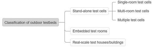
As shown in , the outdoor experimental testbeds may be divided into three general categories by scale and form: stand-alone test cells, embedded test rooms, and real-scale test houses/buildings. Stand-alone test cells are chambers built specially for experimental purposes. They are usually small in size (average area of the test room around 3.0 × 3.0 m), and may contain more than one test rooms and some supplementary space. Depending on the number of test rooms in one cell and the total number of test cells, they are further divided into single-room test cells, multi-room test cells and multiple test cells (a group of individual test cells). Stand-alone test cells may be customized according to various research objectives and require relatively short construction time. Most or all the surfaces of the test cells are exposed to the outdoor environment, which is not a real representation of boundary condition for an office or residential space. In addition, such test cells usually employ simplified service system. Occupants’ effect is excluded in most cases. Embedded test rooms are incorporated in an existing building. Apart from the test room for experiments, the rest space of the building is in practical use such as offices. They usually have one or two surfaces exposed to the outdoor environment, which are used as test surfaces. The rest surfaces subjected to thermal effects from other internal thermal zones, which can be considered as real-world boundary conditions. Real-scale test houses/buildings are houses or buildings that are either initially dedicated to experimental purpose, or originally for practical use such as residence and converted for experiments later. The former requires longer construction time and more funding support compared to the latter. They usually have real-scale HVAC system as well that may participate in the research for more complex tasks. During the test, the house or building may be occupied or not, according to the specific research objective.
Figure 1. Classification of outdoor testbeds for building envelope performance assessment.
2.2. Stand-alone test cells
Stand-alone test cells are individual test chambers. They are usually small in size (average area of test room is around 3 × 3 m), and may include more than one equipment rooms or other supporting areas. According to the number of test rooms and the way they are conjugated, they can be classified into: single-room test cells, multi-room test cells, and multiple test cells.
2.2.1. Single-room test cells
A single-room test cell contains only one room that simulates a working or residential space. Façade material or component is usually installed on one surface and tested. summarizes detailed information of 24 single-room test cells. Some of the single-room test cells also include a supporting space such as buffer zone (approximately 1 m wide), or space for equipment and storage.
Table 1. Examples of single-room test cells.
In 1986, the European Commission launched the Passive Solar Energy Components and Systems Testing (PASSYS) project (Aleo et al. Citation2001; Assimakopoulos et al. Citation2007; Hahne and Pfluger Citation1996; Van Dijk and Van der Linden Citation1993) (), which was the world’s largest research project on methods for assessing the thermal performance of building components at the time. A total of 35 outdoor test cells were built during the project period, 29 of which were designed according to a unified standard and each contained a test room (with an area of 13.8 m2 and a clear height of 2.75 m) and an adjoining equipment room.
Figure 2. PASSYS (Baker and Van Dijk Citation2008).
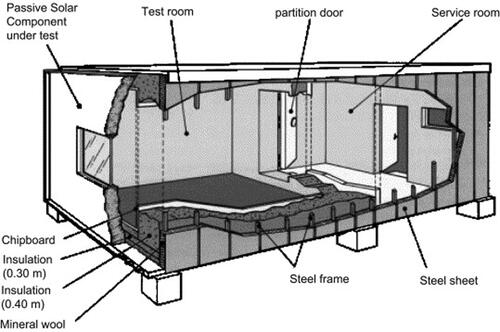
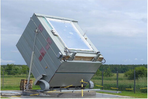
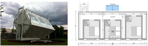
Using the PASSYS test cells as a prototype, more upgraded test cells have been established. For example, the LABIMED test cell (Alcamo and De Lucia Citation2014; Luible et al. Citation2018; Romano, Gallo, and Donato Citation2021) and CIEMAT (Jiménez, Porcar, and Heras Citation2009; Jiménez, Porcar, and Heras Citation2008; Jiménez and Madsen Citation2008) maintained the PASSYS floor plan with an upgrade at the bottom of the structure. shows the layout of LABIMED test cell that included one test room and an auxiliary space/equipment room. It could rotate on a circular platform to allow for targeted testing (). IBP's calorimetric test facility (Kersken Citation2021; Kersken et al. Citation2021) () could rotate 360°and tilt up to 90°, allowing a façade component being tested at any slope and orientation.
Figure 3. Layout of LABIMED test cell (Alcamo and De Lucia Citation2014).
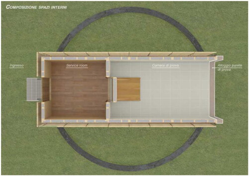
Figure 4. LABIMED test cell (Alcamo and De Lucia Citation2014).
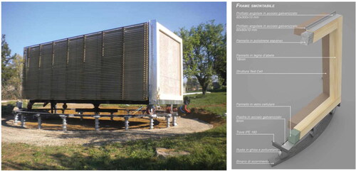
Figure 5. Calorimetric test facility (Kersken Citation2021).
A few test cells were designed to simulate an office environment and occupants were involved during the test, such as the CEC (Ko, Schiavon, et al. 2020) and daylight laboratory (Bakker et al. Citation2014). During the daylighting test (Bakker et al. Citation2014), participants in the experiments were required to sit at a distance of 1.5 m from the window for several hours. Different window configurations were tested and the resulting the indoor environmental conditions and energy use were assessed.
2.2.2. Multi-room test cells
A multi-room test cell contains two or more rooms that simulate identical working or living spaces. Different building envelope components were usually installed and tested in those rooms respectively. Auxiliary spaces such as plant rooms may be contained in the test cell. summarizes detailed information of 23 multi-room test cells.
Table 2. Examples of multi-room test cells.
Most early multi-room test cells contained 2 test rooms, and some of them were rotatable. For example, LBNL constructed the MoWiTT facility (Klems and Keller Citation1986; Klems Citation1992, Citation1988) in 1979 (), which was rotatable and contained 2 test rooms and 1 service room. MATRIX (Ascione, De Masi, et al. Citation2016) was mounted on a rotatable steel structure that was installed on a reinforced platform. Lwf façade facility (Feldmeier Citation2006; Schaefle, Feldmeier, and Lux Citation2012) () was also a rotatable facility, which sat 2 m above the ground level. The external frame enabled the test cell to rotated toward different directions and at any inclination angles.
Figure 6. MoWiTT (a) Field configuration; (b) Plan (Klems Citation1988).
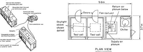
Figure 7. Lwf façade facility (a) Exterior view; (b) Plan (Janssens Citation2016).
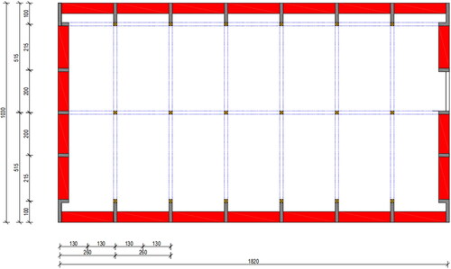
The BSRTU test cell (Buxbaum et al. Citation2008) () was a flexible rectangular box with structural columns placed 1 m back from the wall assembly. Wall or roof sections can be installed between this frame structure according to experimental requirements, allowing for flexible adaptation of the layout of the room.
Figure 8. Layout of the BSRTU test facility (Janssens Citation2016) (Grey blocks indicate the load-bearing structures, red blocks indicate the exterior walls where the facade components will be tested; and the blue lines indicate partition walls).
More complex test cells featured with more than two test rooms were built to accelerate testing speed for comparable studies. The facility at a community college campus in Ankeny (Loutzenhiser, Maxwell, and Manz Citation2007; Price and Smith Citation2000) () contained 8 test rooms, a computer room, an office, 2 classrooms, a mechanical room and a service room. The LBNL test cell (Lee et al. Citation2015, Lee, DiBartolomeo, and Selkowitz Citation2006, 2005) () consisted of three identical side-by-side test cells built with almost identical construction materials to mimic a commercial office environment. The VLIET-test building (Abuku, Blocken, and Roels Citation2009; Desta, Langmans, and Roels Citation2011; Janssens and Hens Citation2007; Langmans and Roels Citation2015; Roels and Deurinck Citation2011; Saelens, Roels, and Hens Citation2004) had multiple flexible walls and test chambers simultaneously. The EMPA facility (Manz Citation2004; Simmler, Binder, and Vonbank Citation2000; Simmler and Binder Citation2008), ZEB test cell (Cattarin et al. Citation2018; Goia, Schlemminger, and Gustavsen Citation2017; Gullbrekken, Kvande, and Time Citation2017), SCUT test cell (Qian, Guan, et al. 2016), LOBSTER (Schweiker et al. Citation2014), etc., also consist of 2 or 3 test cells side by side.
Figure 9. Floor plan of the facility at community college campus in Ankeny (Price and Smith Citation2000).
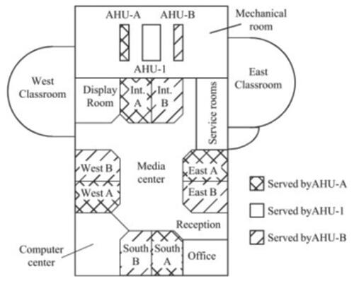
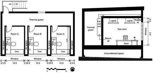
Figure 10. (a) Floor plan and (b) Cross-section of LBNL test cell (Lee et al. Citation2005).
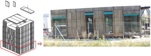
Apart from testing single façade components, it was also possible to evaluate entire façade system. For example, KUBIK () (Chica et al. Citation2011; Elguezabal et al. Citation2020; Garay et al. Citation2015) was designed to test a completely demountable envelope. It allowed reconfiguration and assessment of the façade at the building level. Moreover, INVISO Project (Industrialized Sustainable Housing)(Arranz et al. Citation2020) () aimed to develop a new industrial, lightweight, sustainable and energy-efficient building system, which was capable of harnessing, storing and managing solar passive energy, reducing heating energy demand, and avoiding overheating problems.
Figure 11. Replacing the façade for KUBIK (Janssens Citation2016).
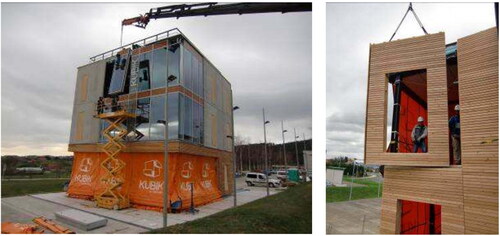
Figure 12. INVISO industrialized sustainable construction system project (Arranz et al. Citation2020).
2.2.3. Multiple test cells
Multiple test cells are a group of identical test cells designed and constructed according to a common standard. They are located in the same site for comparative studies so that the performance indicators are comparable regardless of the climate. summarizes detailed information of 13 multiple test cells.
Table 3. Examples of multiple test cells.
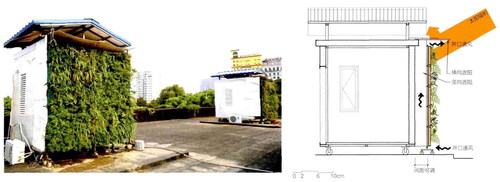
Santo Domingo Campus test cells (Ruiz-Valero et al. Citation2021) () consisted of four experimental cells with an external dimension of 3.00*3.00*3.00m. These test cells had wheels that allow rotation to evaluate the facades in different orientations. HUST test cells (Chen, Liu, et al. Citation2015) () were designed for testing a living wall, and the distance between the living wall and the exterior wall was adjustable between 30 and 600 mm. Slovak University test cells (Curpek, Hraska, and Cekon Citation2018; Čurpek and Čekon Citation2020), University of Seville test cells (Calama-González, León-Rodríguez, and Suárez Citation2022; Domínguez-Torres et al. Citation2022), EGUZKI and ILARGI (García-Gáfaro et al. Citation2022, Citation2020, Citation2012), and TWINS (Serra, Zanghirella, and Perino Citation2010) are all multiple test cells.
Figure 13. Building process of Santo Domingo Campus test cells (Ruiz-Valero et al. Citation2021).
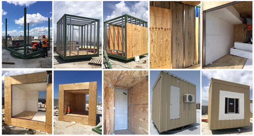
Figure 14. Exterior and wall bulk view of HUST test cells (Chen, Liu, et al. Citation2015).
In summary, stand-alone test cells exhibit large variety in the scale of tested components, ranging from a single small piece of glazing to an entire façade system prototype. For example, with KUBIK (Chica et al. Citation2011; Elguezabal et al. Citation2020; Garay et al. Citation2015) the whole facade structure can be tested. Tests of this scale are more comprehensive and realistic. Early stand-alone test cells have no dedicated functions. Later on, some test rooms have been further defined to represent a typical working space (such as MATELab (Luna-Navarro and Overend Citation2021)) or residential space (such as the University of Seville test cells (Calama-González, León-Rodríguez, and Suárez Citation2022; Domínguez-Torres et al. Citation2022). This helps clarify the test objectives and corresponding needs for mechanical systems and other experimental instrument.
Due to the simple construction and flexibility of stand-alone test cells, the function of test rooms may also be altered according to experimental requirements. Most stand-alone test cells have test rooms directly exposed to the exterior environment. This could lead to over-heating problems that may not be present in a real-world situation, thereby resulting in some bias especially in measuring the performance indicators. Multi-story test cells such as KUBIK (Chica et al. Citation2011; Elguezabal et al. Citation2020; Garay et al. Citation2015) and VERU (Hauser, Sinnesbichler, and Eberl Citation2010; Heusler Citation2011; Sinnesbichler Citation2007; Sinnesbichler and Eberl Citation2009), or those with a buffering zone may alleviate this problem.
2.3. Embedded test rooms
Embedded test rooms are located in the perimeter space of a building. Therefore, at least one surface has access to daylight and view, or to the outdoor environment. Apart from the room itself that are used for experimental purposes, the rest part of the building operates for normal use (such as offices) in most cases. lists 12 embedded test rooms with detailed information.
Table 4. Examples of embedded test rooms.
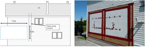
In NRC-IRC team’s Field Exposure of Walls Facility (FEWF) () (Maref et al. Citation2012, Maref, Armstrong, and Rousseau Citation2010), a test bay facing west measuring 7.5 m wide and 3.2 m high is contained in the house. It was possible to test one large façade sample or two small samples. The test bay may be separated thermally with an insulated cavity. Each experiment required full removal of the test bay and complete reconstruction, and re-instrumentation.
Figure 15. (a) Schematic of FEWF (Janssens Citation2016); (b) Insulating concrete form (ICF) wall specimens before installation of siding (Maref et al. Citation2012).
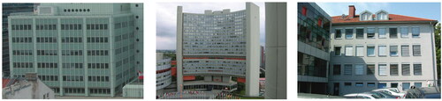
The ARFRISOL project (Bosqued et al. Citation2006; Heras et al. Citation2006; Palero et al. Citation2006; Soutullo et al. Citation2010) () included 5 office buildings of more than 1,000 m2. CDI CIESOL UAL (Bosqued et al. Citation2006; Castilla et al. Citation2011, Citation2013; Heras et al. Citation2006; Palero et al. Citation2006; Soutullo et al. Citation2010), CDI Fd. Barredo Asturias (Janssens Citation2016), and CDI PSA (Bosqued et al. Citation2006; Enríquez et al. Citation2012; Heras et al. Citation2006; Palero et al. Citation2006; Soutullo et al. Citation2010) were newly-built. CDI-70-CIEMAT (Bosqued et al. Citation2006; Heras et al. Citation2006; Palero et al. Citation2006a; Soutullo et al. Citation2010) and CDI-CEDER Cubo Solana (Bosqued et al. Citation2006; Heras et al. Citation2006; Palero et al. Citation2006; Soutullo et al. Citation2010) were renovations of old buildings. They were located in five different representative areas of the Spanish climate. For each building, a few representative rooms were monitored during the experiment. Most of the remaining rooms are used as offices, and a few other rooms were used to demonstrate the role of bioclimatic buildings, solar thermal and photovoltaics in saving energy in future buildings. ESP-r (Beausoleil-Morrison et al. 2008; Beyer and Kelly Citation2008; Clarke et al. Citation1999; Kelly, Tuohy, and Hawkes Citation2014) is similar to the ARFRISOL project. Mahdavi et al. (Mahdavi et al. Citation2008) converted office rooms in three different buildings into test rooms (). FH included a variety of test room sizes, i.e., ten single-occupancy offices, two double-occupancy and one triple-occupancy offices.
Figure 16. Location of the buildings in the ARFRISOL project (Janssens Citation2016).
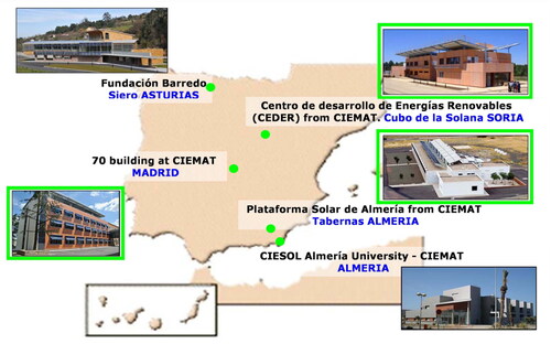
Figure 17. (a) FH, (b) VC and (c) HB (Mahdavi et al. Citation2008).
One on hand, embedded test rooms are particularly suitable for post-occupancy assessment (POA) or applicability tests of a façade technology for a certain architectural type; on the other hand, it put several constraints in terms of location and orientation of the room, function of the building, service system, etc. Construction time is saved, although installation of testing components and corresponding measurement equipment is still required. It is essential to understand the construction details and thermal behavior of the hosting building and calibrate the boundary condition of the test room, before new experiments are carried out. Some embedded test rooms such as in Duplex flat (Bozonnet, Doya, and Allard Citation2011) were on the top floor of the building to test roof components. Test rooms on the top floor have a higher solar radiation exposure and hence it is necessary to be clear about the purpose of the experiment before determining its location in a hosting building.
2.4. Real-scale test houses/buildings
Real-scale test houses/buildings are those entirely dedicated to experimental purposes. lists 16 real-scale test houses/buildings for detailed information. They can be broadly divided into two groups according to the primary design purpose: experimental living lab and privately owned properties under monitoring. The former are real-scale laboratory houses/buildings specially designed and built for empirical studies. Examples include INCAS platform (Gouy-Pailler et al. Citation2011; Ibrahim et al. Citation2015; Spitz et al. Citation2012), EnergyFlexHouse (Jensen et al. Citation2016; Tahersima Citation2012), TWIN Houses (Mantesi et al. Citation2019; Strachan et al. Citation2015), Botticelli project (Causone et al. Citation2019; Erba et al. Citation2019), FLEXLAB (Jia, Pang, and Haves Citation2018; Lee and Hong Citation2019; Pang et al. Citation2018), etc. They could be either used to test a particular technology, or in most cases, to understand the overall performance of the house at a system level. The latter, such as Westfield house (Kelly and Cockroft Citation2011), the Camden Passive House (Ridley et al. Citation2013), Passive House Duplex (Sage-Lauck and Sailor Citation2014), and PH houses (Colclough et al. Citation2018), are existing or newly-built housing with advanced monitoring systems. Their performances are monitored while occupants actually live in. In many cases the houses were designed to satisfy a particular standard such as the nearly Zero Emission Buildings (BNZEB (Ascione, Bianco, et al. Citation2016; Ascione et al. Citation2019, Citation2022)), or to represent a typical housing in its located area (the affordable house (Fensterseifer et al. Citation2022), and they were used to characterize the performance of a state-of-the-art architectural typology or implementation of an advanced system.
Table 5. Examples of real-scale test houses/buildings.
Apart from CBCC Office Building (Mejri, Del Barrio, and Ghrab-Morcos Citation2011) and FLEXLAB (Jia, Pang, and Haves Citation2018; Lee and Hong Citation2019; Pang et al. Citation2018), all others simulated residential environment. This is probably because an office environment is relatively easier to characterize (with more regular occupancy, less freedom of control in building service system) and hence an embedded test-room in an office building would be sufficient. In comparison, residential housing tends to be affected by more variable occupant behaviors.
Most facilities are unique for absolute measurements, but some contain two identical houses, either situated a few meters apart like the Energy Flex Lab (Iqbal et al. Citation2015; Jensen et al. Citation2016; Tahersima Citation2012) and Passive House Testing-building (Mlakar and Štrancar Citation2011), or joint by a common wall like the 2 mirror-image apartment (Sage-Lauck and Sailor Citation2014), which is essentially a two-story building divided into two mirror-image apartments that share a wall on the north–south axis. These buildings may be used for comparative studies. However, when occupants are introduced, different behaviors patterns would make it rather difficult for comparative studies.
Real-scale test buildings undertake the most comprehensive tests, and often take occupancy interactions into consideration when monitoring energy consumption and indoor environmental comforts. Calibration work is needed to understand the thermal behavior of a real-scale test building, before tests of building envelope technologies can be performed. Since the building is relatively complex than test cells or embedded test rooms, a large number of sensors need to be installed for calibration and measurements. Special attention should be paid to minimize the impacts of the measurement equipment itself on the hygrothermal behavior of the test building, such as additional building thermal bridges, local thermal loads, etc. Real-scale test buildings require a dedicated site and ample research funding for design, construction, operation, and maintenance. Additionally, it also needs to involve municipal supports if residential housing were to be employed for experimental studies in many cases. These are probably why the number of real-scale test houses/buildings is significantly lower compared to the number of stand-alone test cells and embedded test rooms.
2.5. Summary
This section reviewed 82 outdoor testbeds for assessing the performance of building envelopes between 1938 and 2023. The testbeds are categorized into three major categories according to scale and form, i.e., stand-alone test cells, embedded test rooms, and real-scale test buildings. Representatives in each category are discussed in details. According to the above analysis, the advantages and disadvantages of testbeds in each category are summarized in .
Table 6. Summary of advantages and disadvantages of testbeds for assessing building envelopes.
Due to the evolution of façade technologies and increasing number of performance parameters to be considered for experiments, the outdoor test facilities have gradually become more complex and diverse. PASSYS and PASLINK projects were undoubtedly exceptional pioneers for test cells, based on which more functions such as rotatable base and tiltable roof were further included later on. Test buildings are constructed from a more practical perspective. Although the outdoor testbeds share the same basic unit – a cube test room, there is a lack of link between different categories, even though test cells could potentially be accommodated by test buildings or test buildings may be decomposed into individual test cells.
3. Experimental objectives of outdoor testbeds
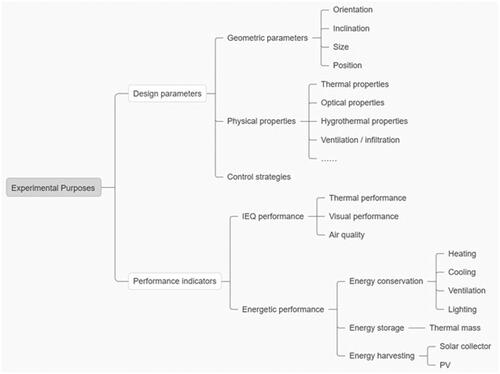
The outdoor testbeds have been employed for investigating the façade design parameters and building performance indicators, as shown in . Some test facilities were constructed to test specific technologies, and others provide opportunities for testing of different technologies and systems, as shown in . Generally, the experimental work that have been done aimed to understand the underlying interactive mechanism between the parameters and indicators.
Figure 18. Classification of experimental purposes.
3.1. Design parameters
Façade geometric parameters are important design factors that may significantly affect building performance. Stand-alone test cells are most frequently used for exploring these parameters. For example, Jaber et al. (Jaber and Ajib Citation2011) achieved a 27.6% annual energy saving by optimizing the façade orientation, window size, insulation thicknesses, etc. MATRIX (Ascione, De Masi, et al. Citation2016) was employed to investigate facades components of different sizes, and the thicknesses of exterior wall. Hans et al. (Simmler and Binder Citation2008) showed the influence of various blind configurations, including slat tilt angle and solar reflectance of the slat surface, on the total solar energy transmittance. The calorimetric test facility (Kersken Citation2021) allowed components to be tested in relation to different angles of solar incidence.
As science and technology continue to develop, more and more new materials and technologies appear. The types of facades have evolved from static to dynamic, from passive to active. Outdoor test facilities have been widely used for understanding the complex effects of the physical properties of facades, including static properties such as U-value (Jiménez, Porcar, and Heras Citation2008; Kotsiris et al. Citation2012; Mandilaras et al. Citation2014), g-value (SHGC) (Clarke et al. Citation2002; Jiménez, Porcar, and Heras Citation2008; Ko, Oh, et al. 2020), and other dynamic properties. For instance, Baker (Baker and Van Dijk Citation2008) used dynamic methods to obtain the thermal and solar characteristics of building components. Dimoudi et al. (Dimoudi, Androutsopoulos, and Lykoudis Citation2004) tested a prototype ventilated wall coupled with dynamic insulation panels and found that the permeability of the intermediate materials must be considered when using a multi-layer component.
The interaction between occupants, façade, and building service system is another important factor that highly affect the indoor environmental quality and energy demand of buildings. Occupant interaction with building envelopes varies from as simple as opening/closing windows based on their thermal sensation, to adoption of advanced control strategies for dynamic façade technologies for improving thermal comfort, visual comfort or indoor air quality. In the study by Bakker et al. (Bakker et al. Citation2014), several experimenters were involved and completed the questionnaire to help understand the logic and patterns of the control-oriented user behavior. Alessandra et al. (Luna-Navarro and Overend Citation2021) captured the effects of facade systems on occupants environmental perception and interaction in MATELab. Ko et al. (Ko, Schiavon et al. 2020) investigated the thermal perception and emotional and cognitive impacts of having a view to the outdoors via a window in a working environment. This will not only help to better predict building performance, but also support the effective operation of building envelopes.
3.2. Performance indicators
3.2.1. Indoor environmental quality (IEQ) performance indicators
IEQ performance, which includes thermal performance, visual performances and air quality, directly affects occupants’ comfort. The indicators for the above aspects may all be assessed with outdoor testbeds.
Thermal performance can be evaluated by: (1) directly measurement of thermal/solar related properties, such as determination of U-values, g-values with the PASSYS and PASLINK test cells; (2) recording the dynamic variations of key factors such as indoor air temperature, relative humidity, air flow rate, wall surface temperature, based on which metrics such as PMV or PPD may be calculated. La Ferla et al. (La Ferla, Román, and Calzada Citation2020b) demonstrated that radiant glass façade technology as a heating device can improve the level of thermal comfort by avoiding radiant asymmetry through a uniform distribution of radiant temperature. In this study, envelope surface temperature, operative, air, radiant temperatures, and radiant asymmetry temperature are measured, and PMV was calculated accordingly. Nicolini et al. (Nicolini et al. Citation2023) analyzed the thermal performance of a façade enclosure integrated by vegetation under windy and rainy climatic conditions, by measuring the wall surface temperatures. Yang et al. (Yang et al. Citation2018) proposed a state-space thermal model incorporating thermal comfort and humidity for model predictive control in buildings, and its performance is evaluated through a case study on the BCA SkyLab test bed facility in Singapore.
Visual performance can be determined by: (1) measuring luminance/illuminance at different points; (2) taking circular fisheye photos, for calculating daylight glare index (DGI) and daylight glare probability (DGP). Bian and Luo (Bian and Luo Citation2017) recorded luminance and illuminance with meters at different points of table level around a participant, and captured circular fisheye images that equal the field of view as seen by the participant. HDR luminance image were produced, from which DGI/DGP were calculated. Benedetti et al. (Benedetti et al. Citation2019) developed HDR vision sensors to capture luminance maps continuously, from which vertical illuminance and DGP may be extracted.
Assessment of air quality usually includes measurements of ventilation rate, relative humidity, vapor pressure excess, and CO2 concentrations. Examples can be found in Ridley et al. (Ridley et al. Citation2014) and Colclough et al. (Colclough et al. Citation2018). Epidemiological evidence suggests that the presence of mold growth in buildings can have a detrimental effect on the well-being of occupants. A study by Clarke et al. (Clarke et al. Citation1999) looked into infectious aerosols and developed a predictive tool to prevent the likelihood and extent of mold infestation, and its predictive capability was tested against monitored data and mycological samples taken from a mold-infested house.
In addition to the above-mentioned objective measurements, subjective questionnaires may be collected from participants/occupants for understanding their thermal comfort (Schweiker et al. Citation2012), visual comfort (Benedetti et al. Citation2019; Bian and Luo Citation2017), and satisfaction with air quality (Colclough et al. Citation2018).
3.2.2. Energetic performance indicators
With the aim of assessing the energy efficiency of advanced building envelopes at system/building level under real weather conditions, they are often tested using outdoor testbeds installed with HVAC systems. According to , 90% of the reviewed testbeds provided specific descriptions on their HVAC systems, and the corresponding energy consumption for heating, cooling, and ventilation can be measured. The rest either intentionally excluded the effects of HVAC systems to simulate a common local situation like Bozonnet, Doya, and Allard Citation2011) and (Fensterseifer et al. Citation2022), or had research focuses excluding energetic performances like Wienold and Christoffersen (Wienold and Christoffersen Citation2006).
The HVAC systems are generally simpler and more flexible for single-room, multi-room, and multiple test cells, as shown in . A ventilation system with heating and cooling unit, electric radiators, air conditioners, and fans were mostly adopted. Floor heating (Mohammadi et al. Citation2022; Soudian and Berardi Citation2022) and ceiling heating/cooling (Lwf-FAÇADE-facility (Laboratory for Intelligent Building Technology Citation2011) were also possible. More complex HVAC systems can be found in embedded test rooms and real-scale test houses/buildings. For instance, EnergyFlexHouse (Iqbal et al. Citation2015; Jensen et al. Citation2016; Tahersima Citation2012) adopts hydronic central heating system with an electrically driven heat pump as the heat source, which is connected to a network of sub-floor heating pipes and radiators. KUBIK had a hydronic system and a Variable Air Volume (VAV) system. CIESOL building (Bosqued et al. Citation2006; Castilla et al. Citation2013; Heras et al. Citation2006.; Palero et al. Citation2006; Soutullo et al. Citation2010) is installed with HVAC systems based on solar cooling using a solar collector field, a hot water storage system, a boiler, and absorption machine with its refrigeration tower. Radiant ceiling panel (RCP) system and the radiant slab (RS) system are equipped in Flexlab (Jia, Pang, and Haves Citation2018; Lee and Hong Citation2019; Pang et al. Citation2018). Apart from those, simpler heating devices such as electric radiators could also be used as additional heating source (Colclough et al. Citation2018). Therefore, with such embedded test rooms and real-scale test houses/buildings, a more realistic indoor environment can be achieved, and detailed measurements and analysis can be carried out for a specific and innovative type of HVAC system. The only concern is that if the test house/building was not initially designed solely for experimental purpose, the addition of monitoring system may encounter some constraints in installation and introduce uncertainties to experimental data. For example, in the Camden Passive House (Ridley et al. Citation2013), the monitoring system measures the domestic hot water consumption and the heat input to the cylinder from the solar thermal system, but the heat input to the cylinder from the boiler and the cylinder temperature are not directly measured. Similarly, it would have been ideal to directly measure the total heat output of the boiler, in order to correctly calculate the boiler efficiency. However, the installation of such a monitoring system to the Viessmann system post installation would be difficult and compromise the warranty.
HVAC systems may play different roles in helping assess the performance of building envelopes. Firstly, they can be used to simulate internal heat gain when occupants are absent. For instance, in COOLSKIN test facility (Bröthaler et al. Citation2021) a heat load of 300 W was activated to simulate the internal thermal loads. Secondly, they keep room air temperature constant to deactivate thermal mass, like in PASSYS project. Thirdly, they are operated according to rule-based control manners and used to measure energy consumption. Dimoudi et al. (Dimoudi, Androutsopoulos, and Lykoudis Citation2004) and Shahrzad et al. (Soudian and Berardi Citation2022) evaluated the cooling performance of cool selective coating and ventilated facades, respectively. Lee et al. (Lee, DiBartolomeo, and Selkowitz Citation2006) demonstrated the first generation of prototype electrochromic window and daylighting control system, and monitored the cooling load and visual comfort of this technology. Fouthly, they are used to study the combinatorial energetic and comfort performance of advanced building envelopes with occupant interaction and advanced HVAC and lighting control strategies. (Yang et al. Citation2018) and (Castilla et al. Citation2013) both investigated thermal effects of model predictive control strategies in building automation and control. Mahdavi et al. (Mahdavi et al. Citation2008) observed user control actions pertaining to lighting, and assessed lighting energy saving potential due to consideration of occupancy and behavioral patterns in office buildings.
From the energy storage point of view, the study of material properties is also very important. Ibrahim et al. (Neya et al. Citation2021) tested the relationship between the thickness of the brick materials and thermal mass. Umberto et al. (Berardi and Soudian Citation2023) studied a radiant ceiling panel system with thermal energy storage in BeTOP. (Rouault et al. Citation2014) conducted a study on a low temperature phase-change materials (PCMs) thermal energy exchange and storage system. Sage-Lauck et al. (Sage-Lauck and Sailor Citation2014) found that installation of the PCMs had a positive effect on thermal comfort. Marine et al. (Auzeby et al. Citation2016) demonstrated the potential contribution of PCMs in reducing overheating risks.
With the help of outdoor testbeds, solar thermal collector and PV for energy harvesting were tested to understand the total energy flow through and captured by building envelopes. Heras et al. (Heras et al. Citation2001) developed optimal solar collectors for building integration in ARCHINT project. Experiments have been carried out With KUBIK (Garay et al. Citation2015) on solar thermal collector on facades and obtained a patent for a Passive Solar Collector Module for building envelopes (09812437.3, EP 2520 870 A1). García-Gáfaro et al. (García-Gáfaro et al. Citation2022) demonstrated the potential of one particular photovoltaic forced ventilated façade (PV-FVF) in latent thermal energy storage (TES). Jakub Čurpek and Miroslav Čekon (Čurpek and Čekon Citation2020) integrated a ventilated BiPV façade system with PCM, and investigated its influence on the thermal and energy performance. Other tests of photovoltaics on facades (Bröthaler et al. Citation2021; Dehra Citation2019) were also beneficial for understanding the integrative mechanism of PV and the entire façade system, and increasing the energy-efficiency of buildings.
4. Materials and construction
Research on facades carried out with stand-alone test cells, embedded test rooms and real-scale test buildings have shown different emphasis in terms of experimental scope. According to , stand-alone test cells are mainly oriented toward component and/or room level, while embedded test rooms and real-scale test buildings are more oriented toward room and/or building level, and provides more opportunity to take into account effects of occupants’ behaviors. This difference in a way affects the choice of materials and construction techniques.
Stand-alone test cells were usually designed as a simple chamber or their aggregation. The size of a single test room is of the smallest suitable dimension for the activities of experimenters. More than 90% of the 52 reviewed stand-alone test cells are constructed of light steel, timber or light steel-wood construction. For example, SCUT test cells and GESLAB test cells (Alonso et al. Citation2016; La Ferla, Román, and Calzada 2020) are light steel structures. LABIMED test cells (Romano, Gallo, and Donato Citation2021; Luible et al. Citation2018; Alcamo and De Lucia Citation2014) are made of steel and wood. Such structures are economical, light in weight, require short construction period on site. Most test cells are placed on platforms with no surrounding shade, such as in an open place like the Smart TinyLab (Mohammadi et al. Citation2022), or on the rooftop of an existing building like the SCUT test cell (Lu et al. Citation2019). For the latter case, a light weight structure is necessary, because usually the exiting building roof was not initially designed to take additional large concentrated load. Due to their site and experimental purpose, the stand-alone test cells are usually exposed to the exterior environment entirely, which brings a challenge for maintenance especially when the major materials are steel or timber. No protection/maintenance routines were mentioned in the literature so far, which is probably the reason why around 25% of the stand-alone test cells were only reported once in a study.
Embedded test rooms typically maintain the structure and material of the original hosting building. According to , at least half of the reviewed embedded test rooms are hosted by concrete buildings such as the FEWF (Maref et al. Citation2007), FH/VC/HB buildings (Mahdavi et al. Citation2008), and Building No. 5 (Daemei et al. Citation2021). Reinforced concrete structures have stronger weather resistance and require less maintenance work. These test rooms also offered superior opportunities to evaluate the façade performance in buildings with high thermal mass. Since host buildings usually have already been in use for some time, careful inspection should be done on its current condition, including insulation, infiltration, possible damaged connections and so on, before new experiments are performed. Embedded test rooms show less flexibility compared to test cells, mainly because of the constraints brought by the host building that the structure/wall of concrete cannot be easily altered. Out of the 12 test rooms listed in , only 4 was reported to have changes on their envelopes, i.e., for the Duplex flat (Bozonnet, Doya, and Allard Citation2011) a cool selective coating was applied on the roof, and tests were carried out in order to quantify the improvement in the indoor thermal environment; FEWF (Maref et al. Citation2007) hosted a test room with one façade interchangeable; Building No. 5 (Daemei et al. Citation2021) and Electricity substation (Lee and Jim Citation2019) both were installed with green walls. All other test rooms have operable or switchable facades/shadings that were measured as is.
According to , around 2/3 of the real-scale test buildings mainly adopt timber/steel structure, and the rest are masonry/concrete structures. For test houses that are initially designed for experimental purposes, steel or timber structures requires a shorter construction cycle and offers higher reconfigurability. For example, KUBIK (Chica et al. Citation2011; Elguezabal et al. Citation2020; Garay et al. Citation2015) adopted steel structure that was totally demountable and allowed reconfiguration of the scenarios at construction level. The components of the envelope, the roof, the floors and the partitions can all be exchangeable. For test houses/buildings that offer both residential and experimental use, the choice of construction materials is mainly dependent on the architectural typology and its construction time. For instance, the Westfield house (Kelly and Cockroft Citation2011) constructed between 1938 and 1969 were masonry structures, while the Camden Passive House (Ridley et al. Citation2013) adopted timber structure. These test houses/buildings either have refurbished or new high-performance envelopes that were measured as is without changing.
5. Design, construction, and use of future outdoor test facilities
5.1. Standardization of design and use
Through previous study on existing outdoor testbeds, it is not difficult to find that the test facilities can be used either as a “customized” experimental instrument for a particular test, or as a “universal” instrument to provide experimental testing of the performance of various facade materials and components under different climatic conditions. Both from an economic point of view and for the purpose of continuation and expansion of research activities, the future outdoor testbeds should aim toward the latter. The PASSYS (Aleo et al. Citation2001; Assimakopoulos et al. Citation2007; Hahne and Pfluger Citation1996; Van Dijk and Van der Linden Citation1993) and PASLINK (Baker and Van Dijk Citation2008; Dimoudi, Androutsopoulos, and Lykoudis Citation2004; García-Gáfaro et al. Citation2020; Goethals et al. Citation2012; Kotsiris et al. Citation2012; Leal and Maldonado Citation2008) projects in Europe are good examples. They provide standards not only in facility design but also in testing procedures. However, after the two projects, few projects continue with this methodology. More customized test cells were constructed at a particular location by a specific institution. This makes the measurement result valid only for one climate type, and less possible for cross-comparison between different climates.
In terms of testbed types, stand-alone test cells and real-scale test houses/buildings are more suitable for standardization design than embedded test rooms, because important factors such as boundary conditions and orientations of embedded test rooms are largely dependent on the hosting building that is difficult for adjustment. Stand-alone test cells require a relatively lower budget than real-scale test houses/buildings. Single and multiple test cells show the highest flexibility, since additional ones may be quickly constructed as further study requires. Multi-room test cells with an auxiliary zone for the service system are more comprehensive, because they satisfy the need of both absolute and comparative experiments. Standardized real-scale test buildings, such as Flexlab (Jia, Pang, and Haves Citation2018; Lee and Hong Citation2019; Pang et al. Citation2018), are ideal for obtaining results that best reflect the real performance, because more advanced HVAC systems may be installed and measurement can be carried out not only at the component level, but also at the system/building level. No matter which type of testbeds is chosen, functions should be well defined and a consistent design and construction process should be developed accordingly. Geometric parameters, layout of the test rooms and auxiliary space, materials, connections, and service systems should be identical to make sure the experimental results are comparable among testbeds located in different places. Corresponding testing devices and measuring procedures should also follow the same guideline.
At the same time, scientific alliances can be formed between research institutions in different countries to help the promotion of standardized experimental facilities. Experimental results can be collected through a common database for cross-comparison and complementarity on the basis of data sharing and even deeper mining of technical data.
5.2. Flexibility enhancement based on prefabricated modular design strategies
The research for the construction of the outdoor laboratory takes place in the era of rapid development of prefabricated assembly technology, when there is a continuous and dynamic interaction between diverse requirements and standardized technical routes. As a mockup facility, the role of a future outdoor testbeds is to undertake the most diverse research tasks, including assessing complex and advanced building envelope systems in response to various modes of energy use. Most existing facilities only have one elevation or part of it (e.g., window) that is reconfigurable, while all other parts are fixed. Particularly, few has possibility of various testing roof components. Adaptability of test room dimension is also limited. In addition, the test facilities are all designed as is, without possibility of extension. The best design strategy is to develop modular components that is efficient for installation, disassembly, replacement, and reconfiguration It may also facilitate obtaining primary products.
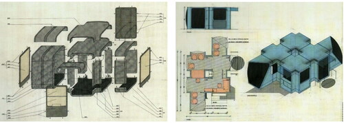
This may be achieved by two levels of modules, i.e., component modules and space modules, which have already been successfully applied in small scale prefabricated construction such as Kiosk K67 () (Stierli, Kulić, and Klarin Citation2018). Component modules provide the flexibility of changing tested modules, connections, wall construction, and the shape and dimension of a single test room. Space modules provide flexibility in the layout and relationship between test rooms. In doing so, components are easily replaceable and spaces are easily combinable, which is a viable way to obtain superior adaptability of the laboratory space and its envelope systems. Single-room test cells may be conjugated to form multi-room test cells, which may then be upgraded to outdoor test buildings to satisfy experimental objectives of different levels of complexity. It should be noted that apart from composition of test room modules, compatibility of auxiliary components such as staircases for multi-story test buildings and HVAC systems should also be considered.
Figure 19. Decomposition and composition of Kiosk K67 (Stierli, Kulić, and Klarin Citation2018).
5.3. Establishment of long-term measurement mechanism
Most studies with outdoor testbeds were conducted in days, weeks or months, while only a few real-scale test houses ran for more than a year. Welsh Passive Houses (Ridley et al. Citation2014) and Camden Passive House (Ridley et al. Citation2013) were monitored for 2 years for understanding the performance of newly built houses in Welsh and London according to Passive House Standards. An IEQ repository was developed that involved over 20 dwellings to provide valuable insights into the long-term performance of the dwellings in both the Republic of Ireland and Northern Ireland (UK) (Colclough et al. Citation2018). In fact, short-term monitoring, or measuring of the first 1–2 years of newly built houses are not always sufficiently representative of the long-term building performance. The quality of maintenance, degradation of construction materials and building service systems, replacement of certain components, change of occupancy or occupants’ behavior all possibly affect the performance of a building in its service life. In addition to short-term characterization, long-term measurement mechanism is required to be established for fully understanding the individual performance of building envelopes and its combinatorial effects on the entire house/building at the system level.
6. Conclusions
This paper analyzed 82 outdoor testbeds for assessing the performance of building envelopes between 1938 and 2023. It aims to provide a comprehensive review and summary of existing outdoor test facilities, and to propose useful suggestions for future design and use of them.
The testbeds are categorized into three major categories according to scale and form, i.e., stand-alone test cells, embedded test rooms, and real-scale test buildings. Representatives in each category are discussed in details, and the main features are compared and summarized systematically. The functions of testbeds are analyzed according to the dedicated experimental purposes. The historical evolvement of the testbeds was discussed to identify the main trends in the development of outdoor testbeds. Different construction materials and structures were also compared to identify suitable choices for testbeds of different scales and research objectives.
On the basis of previous review and analysis, recommendations are proposed for future design, construction and application of outdoor test facilities for assessing performance of building envelopes. Both from an economic point of view and for the purpose of continuation and expansion of research activities, future outdoor testbeds should develop toward a more universal route with diverse testing capabilities. Standardized design, construction, maintenance, and testing procedures should be established to ensure the long-term validity and cross-comparability of studies based on testbeds located in different places. Prefabricated modular design strategies can be employed to enhance the flexibility in the scale and functions of testbeds. A long-term testing mechanism is essential for better understanding of the performance of building envelopes at system level.
Disclosure statement
No potential conflict of interest was reported by the author(s).
Additional information
Funding
Notes on contributors
Qian Jin
Qian Jin, PhD, is an Associate Professor. Qiuting Sun, BA, is a Master Student. Gang Meng, PhD is an Associate Professor.
References
- Abuku, M., B. Blocken, and S. Roels. 2009. Moisture response of building facades to wind-driven rain: Field measurements compared with numerical simulations. Journal of Wind Engineering and Industrial Aerodynamics 97 (5–6):197–207. doi:10.1016/j.jweia.2009.06.006.
- Agency, I. E. 2013. Technology Roadmap Energy Efficient Building Envelopes. OECD 68.
- Akram, M. W., M. Hasannuzaman, E. Cuce, and P. M. Cuce. 2023. Global technological advancement and challenges of glazed window, facade system and vertical greenery-based energy savings in buildings: A comprehensive review. Energy and Built Environment 4 (2):206–26. doi:10.1016/j.enbenv.2021.11.003.
- Alcamo, G., and M. De Lucia. 2014. A new test cell for the evaluation of thermo-physical performance of facades building components. International Journal of Sustainable Energy 33 (4):954–62. doi:10.1080/14786451.2013.796943.
- Aleo, F., A. Pennisi, S. Scalia, and F. Simone. 2001. Optical and energetic performances of an electrochromic window tested in a “PASSYS” cell. Electrochimica Acta 46 (13–14):2243–9. doi:10.1016/S0013-4686(01)00367-X.
- Alkhatib, H., P. Lemarchand, B. Norton, and D. T. J. O'Sullivan. 2021. Deployment and control of adaptive building facades for energy generation, thermal insulation, ventilation and daylighting: A review. Applied Thermal Engineering 185:116331. doi:10.1016/j.applthermaleng.2020.116331.
- Alonso, C., I. Oteiza, J. García-Navarro, and F. Martín-Consuegra. 2016. Energy consumption to cool and heat experimental modules for the energy refurbishment of façades. Three case studies in Madrid. Energy and Buildings 126:252–62. doi:10.1016/j.enbuild.2016.04.034.
- Ango, S. B. E. 2011. Contribution au stockage d’énergie thermique en bâtiment: développement d’un système actif à matériaux à changement de phase. Doctoral dissertation, Arts et Métiers ParisTech.
- Arranz, B., L. Ruiz-Valero, M. P. González, and S. V. Sánchez. 2020. Comprehensive experimental assessment of an industrialized modular innovative active glazing and heat recovery system. Energy 212:118748. doi:10.1016/j.energy.2020.118748.
- Ascione, F., N. Bianco, F. de Rossi, R. F. De Masi, and G. P. Vanoli. 2016. Concept, design and energy performance of a net zero-energy building in Mediterranean climate. Procedia Engineering 169:26–37. doi:10.1016/j.proeng.2016.10.004.
- Ascione, F., M. Borrelli, R. F. De Masi, F. de Rossi, and G. P. Vanoli. 2019. A framework for NZEB design in Mediterranean climate: Design, building and set-up monitoring of a lab-small villa. Solar Energy.184:11–29. doi:10.1016/j.solener.2019.03.083.
- Ascione, F., R. F. De Masi, F. de Rossi, S. Ruggiero, and G. P. Vanoli. 2016. MATRIX, a multi activity test-room for evaluating the energy performances of ‘building/HVAC’ systems in Mediterranean climate: Experimental set-up and CFD/BPS numerical modeling. Energy and Buildings 126:424–46. doi:10.1016/j.enbuild.2016.05.044.
- Ascione, F., R. F. De Masi, A. Gigante, and G. P. Vanoli. 2022. Resilience to the climate change of nearly zero energy-building designed according to the EPBD recast: Monitoring, calibrated energy models and perspective simulations of a Mediterranean nZEB living lab. Energy and Buildings 262:112004. doi:10.1016/j.enbuild.2022.112004.
- Assimakopoulos, M. N., A. Tsangrassoulis, M. Santamouris, and G. Guarracino. 2007. Comparing the energy performance of an electrochromic window under various control strategies. Building and Environment 42 (8):2829–34. doi:10.1016/j.buildenv.2006.04.004.
- Auzeby, M., S. Wei, C. Underwood, J. Tindall, C. Chen, H. Ling, and R. Buswell. 2016. Effectiveness of using phase change materials on reducing summer overheating issues in UK residential buildings with identification of influential factors. Energies 9 (8):605. doi:10.3390/en9080605.
- Baker, P. H., and H. A. L. Van Dijk. 2008. PASLINK and dynamic outdoor testing of building components. Building and Environment 43 (2):143–51. doi:10.1016/j.buildenv.2006.10.009.
- Bakker, L. G., E. C. M. Hoes-van Oeffelen, R. Loonen, and J. L. Hensen. 2014. User satisfaction and interaction with automated dynamic facades: A pilot study. Building and Environment 78:44–52. doi:10.1016/j.buildenv.2014.04.007.
- Balali, A., and A. Valipour. 2020. Identification and selection of building facade’s smart materials according to sustainable development goals. Sustainable Materials and Technologies 26: E 00213. doi:10.1016/j.susmat.2020.e00213.
- Beausoleil-Morrison, I., and U. Arndt, Systems, I.E.C. in B.& C.S.P.A. 42–S. of B.-I.F.C. and O.C. 2008. An experimental and simulation-based investigation of the performance of small-scale fuel cell and combustion-based cogeneration devices serving residential buildings: Final report of Annex 42 of the International Energy Agency’s Energy Conservation in Buildings and Community Systems Programme Ottawa. ON, Canada: Natural Resources Canada.
- Benedetti, M., L. Maierová, C. Cajochen, A. Motamed, M. Münch, and J. L. Scartezzini. 2019. Impact of dynamic lighting control on light exposure, visual comfort and alertness in office users. Journal of Physics: Conference Series 1343 (1):012160. doi:10.1088/1742-6596/1343/1/012160.
- Berardi, U., and S. Soudian. 2023. Outdoor test facilities for the experimental performance evaluation of construction materials and systems: The BeTOP case. Case Studies in Construction Materials 18: E 01920. doi:10.1016/j.cscm.2023.e01920.
- Beyer, D., and N. Kelly. 2008. Modelling the behaviour of domestic micro-cogeneration under different operating regimes and with variable thermal buffering. In Micro-Cogen 2008, 1st International Conference on Micro-Cogeneration Technologies and Applications.
- Bian, Y., and T. Luo. 2017. Investigation of visual comfort metrics from subjective responses in China: A study in offices with daylight. Building and Environment 123:661–71. doi:10.1016/j.buildenv.2017.07.035.
- Bianco, L., P. Schneuwly, E. Wurtz, and A. Brun. 2017. Design of a new full-scale facility for building envelope test: FACT (FACade Tool). Energy Procedia.111:256–66. doi:10.1016/j.egypro.2017.03.027.
- Bigot, D. 2011. Contribution à l’étude du couplage énergétique enveloppe/système dans le cas de parois complexes photovoltaïques (pc-pv). Doctoral dissertation, Université de la Réunion.
- Bosqued, A., S. Palero, C. San Juan, S. Soutullo, R. Enríquez, J. A. Ferrer, J. Martí, J. Heras, J. D. Guzmán, and M. J. Jiménez. 2006. Arfrisol, bioclimatic architecture and solar cooling project. In Proceedings of PLEA2006 Passive Low Energy Archit Geneva, Switzerland.
- Bozonnet, E., M. Doya, and F. Allard. 2011. Cool roofs impact on building thermal response: A French case study. Energy and Buildings 43 (11):3006–12. doi:10.1016/j.enbuild.2011.07.017.
- Bröthaler, T., M. Rennhofer, D. Brandl, T. Mach, A. Heinz, G. Újvári, H. C. Lichtenegger, and H. Rennhofer. 2021. Performance analysis of a facade-integrated photovoltaic powered cooling system. Sustainability 13 (8):4374. doi:10.3390/su13084374.
- Buxbaum, C., O. Pankratz, M. Schorer, and W. Thalhammer. 2008. Habitable basement concepts made in timber construction—assessment on the durability of walls and floor slabs made of solid cross-laminated timber boards. In Proceedings of the 10th World Conference on Timber Engineering, 2–5. Miyazaki, Japan.
- Calama-González, C. M., Á. L. León-Rodríguez, and R. Suárez. 2022. Assessing thermal comfort in the Mediterranean social housing stock through test cells: Comparison of double-skin, externally insulated and non-retrofitted facades. Case Studies in Thermal Engineering 38:102369. doi:10.1016/j.csite.2022.102369.
- Castilla, M., J. D. Álvarez, M. Berenguel, F. Rodríguez, J. L. Guzmán, and M. Pérez. 2011. A comparison of thermal comfort predictive control strategies. Energy Building 43:2737–46. doi:10.1016/j.enbuild.2011.06.030.
- Castilla, M., J. D. Álvarez, M. G. Ortega, and M. R. Arahal. 2013. Neural network and polynomial approximated thermal comfort models for HVAC systems. Building and Environment 59:107–15. doi:10.1016/j.buildenv.2012.08.012.
- Cattarin, G., F. Causone, A. Kindinis, and L. Pagliano. 2016. Outdoor test cells for building envelope experimental characterisation – a literature review. Renewable and Sustainable Energy Reviews 54:606–25. doi:10.1016/j.rser.2015.10.012.
- Cattarin, G., L. Pagliano, F. Causone, A. Kindinis, F. Goia, S. Carlucci, and C. Schlemminger. 2018. Empirical validation and local sensitivity analysis of a lumped-parameter thermal model of an outdoor test cell. Building and Environment 130:151–61. doi:10.1016/j.buildenv.2017.12.029.
- Causone, F., A. Tatti, M. Pietrobon, F. Zanghirella, and L. Pagliano. 2019. Yearly operational performance of a nZEB in the Mediterranean climate. Energy and Buildings 198:243–60. doi:10.1016/j.enbuild.2019.05.062.
- Chen, B., Y. Liu, X. Song, R. Zhao, and J. Sun. 2015. Study on thermal performance of house with closed loop solar air heating coupled TCM (in Chinese). Building Science 31 (08):122–6.
- Chen, Q., B. Li, X. Liu, and X. Li. 2015. Experimental research on the thermal behavior of the living wall system in hot-Summer and cold winter areas (in Chinese). Dyn. Eco-City Green Building (01):120–4.
- Chica, J. A., I. Apraiz, P. Elguezabal, M. O. Rrips, V. Sánchez, and B. Tellado. 2011. KUBIK: Open building approach for the construction of an unique experimental facility aimed to improve energy efficiency in buildings. Open House International 36 (1):63–72. doi:10.1108/OHI-01-2011-B0008.
- Ciampi, G., Y. Spanodimitriou, M. Scorpio, A. Rosato, and S. Sibilio. 2021. Energy performance of PVC-Coated polyester fabric as novel material for the building envelope: Model validation and a refurbishment case study. Journal of Building Engineering 41:102437. doi:10.1016/j.jobe.2021.102437.
- Clarke, J. A., J. Cockroft, S. Conner, J. W. Hand, N. J. Kelly, R. Moore, T. O’Brien, and P. Strachan. 2002. Simulation-assisted control in building energy management systems. Energy and Buildings 34 (9):933–40. doi:10.1016/S0378-7788(02)00068-3.
- Clarke, J. A., C. M. Johnstone, N. J. Kelly, R. C. McLean, J. A. Anderson, N. J. Rowan, and J. E. Smith. 1999. A technique for the prediction of the conditions leading to mould growth in buildings. Building and Environment 34 (4):515–21. doi:10.1016/S0360-1323(98)00023-7.
- Colclough, S., O. Kinnane, N. Hewitt, and P. Griffiths. 2018. Investigation of nZEB social housing built to the Passive House standard. Energy and Buildings 179:344–59. doi:10.1016/j.enbuild.2018.06.069.
- Čurpek, J., and M. Čekon. 2020. Climate response of a BiPV façade system enhanced with latent PCM-based thermal energy storage. Renewable Energy 152:368–84. doi:10.1016/j.renene.2020.01.070.
- Curpek, J., J. Hraska, and M. Cekon. 2018. Multi-functional ventilated BiPV façade concept coupled with PCM BOOK Ext. 47–50, Coimbra.
- Daemei, A. B., E. Shafiee, A. A. Chitgar, and S. Asadi. 2021. Investigating the thermal performance of green wall: Experimental analysis, deep learning model, and simulation studies in a humid climate. Building and Environment 205:108201. doi:10.1016/j.buildenv.2021.108201.
- De Dear, R., A. Nathwani, C. Cândido, and D. Cabrera. 2013. The next generation of experientially realistic lab-based research: The University of Sydney’s Indoor Environmental Quality Laboratory. Architectural Science Review 56 (1):83–92. doi:10.1080/00038628.2012.745807.
- Dehra, H. 2019. Integrated acoustic and thermo-fluid insulation modeling of an airflow window with a photovoltaic solar wall. In Integrated Acoustic and Thermo-Fluid Insulation Modeling of an Airflow Window with a Photovoltaic Solar Wall. Presented at the Building Simulation 2019, Kalyanova and Heiselberg, Rome, Italy, 2–9.
- Desta, T. Z., J. Langmans, and S. Roels. 2011. Experimental data set for validation of heat, air and moisture transport models of building envelopes. Building and Environment 46 (5):1038–46. doi:10.1016/j.buildenv.2010.11.002.
- Dimoudi, A., A. Androutsopoulos, and S. Lykoudis. 2004. Experimental work on a linked, dynamic and ventilated, wall component. Energy and Buildings 36 (5):443–53. doi:10.1016/j.enbuild.2004.01.048.
- Domínguez-Torres, C.-A., R. Suárez, A. L. León-Rodríguez, and A. Domínguez-Delgado. 2022. Experimental validation of a dynamic numeric model to simulate the thermal behavior of a facade. Applied Thermal Engineering 204:117686. doi:10.1016/j.applthermaleng.2021.117686.
- Elguezabal, P., A. Lopez, J. M. Blanco, and J. A. Chica. 2020. CFD model-based analysis and experimental assessment of key design parameters for an integrated unglazed metallic thermal collector façade. Renewable Energy 146:1766–80. doi:10.1016/j.renene.2019.07.151.
- Enríquez, R., M. J. Jiménez, and M. del Rosario Heras. 2012. Analysis of a solar office building at the South of Spain through simulation model calibration. Energy Procedia 30:580–9. doi:10.1016/j.egypro.2012.11.068.
- EPFL. 2020. Controlled Environments for Living Lab Studies (CELLS). https://www.epfl.ch/labs/hobel/home-2/facilities/controlled-environments-for-living-lab-studies-cells/.
- Erba, S., L. Pagliano, S. C. Shandiz, and M. Pietrobon. 2019. Energy consumption, thermal comfort and load match: Study of a monitored nearly Zero Energy Building in Mediterranean climate. Presented at the IOP Conference Series: Materials Science and Engineering, IOP Publishing 609 (6):062026.
- Favoino, F., M. Doya, R. C. G. M. Loonen, F. Goia, C. Bedon, and F. Babich. 2018. Building performance simulation and characterisation of adaptive facades – Adaptive facade network. TU Delft Open.
- Favre, B., and B. Peuportier. 2014. Application of dynamic programming to study load shifting in buildings. Energy and Buildings 82:57–64. doi:10.1016/j.enbuild.2014.07.018.
- Feldmeier, F. 2006. Klimabelastung und Lastverteilung bei Mehrscheiben‐Isolierglas. Stahlbau 75 (6):467–78. doi:10.1002/stab.200610050.
- Fensterseifer, P., E. Gabriel, R. Tassi, D. G. A. Piccilli, and B. Minetto. 2022. A year-assessment of the suitability of a green façade to improve thermal performance of an affordable housing. Ecological Engineering 185:106810. doi:10.1016/j.ecoleng.2022.106810.
- Garay, R., J. A. Chica, I. Apraiz, J. M. Campos, B. Tellado, A. Uriarte, and V. Sanchez. 2015. Energy efficiency achievements in 5 years through experimental research in KUBIK. Energy Procedia.78:865–70. doi:10.1016/j.egypro.2015.11.009.
- García-Gáfaro, C., A. Erkoreka, C. Escudero-Revilla, I. Flores, J. Martínez-Fontecha, and J. M. Sala Lizarraga. 2012. Experience gained in the thermal characterization of building components by using PASLINK test cells. In 5th International Building Physics Conference (IBPC), Kyoto.
- García-Gáfaro, C., C. Escudero-Revilla, I. Flores-Abascal, A. Erkoreka-González, and K. Martín-Escudero. 2020. Dynamical edge effect factor determination for building components thermal characterization under outdoor test conditions in a PASLINK test cell: A methodological proposal. Energy and Buildings 210:109741. doi:10.1016/j.enbuild.2019.109741.
- García-Gáfaro, C., C. Escudero-Revilla, I. Flores-Abascal, J. M. Hidalgo-Betanzos, and A. Erkoreka-González. 2022. A photovoltaic forced ventilated façade (PV-FVF) as heat source for a heat pump: Assessing its energetical profit in nZEB buildings. Energy and Buildings 261:111979. doi:10.1016/j.enbuild.2022.111979.
- Goethals, K., M. Delghust, G. Flamant, M. De Paepe, and A. Janssens. 2012. Experimental investigation of the impact of room/system design on mixed convection heat transfer. Energy and Buildings 49:542–51. doi:10.1016/j.enbuild.2012.03.017.
- Goia, F., L. Finocchiaro, and A. Gustavsen. 2015. The ZEB Living Laboratory at the Norwegian University of Science and Technology: A zero emission house for engineering and social science experiments. In Proceedings of 7PHN Sustainable Cities and Buildings.
- Goia, F., C. Schlemminger, and A. Gustavsen. 2017. The ZEB Test Cell Laboratory. A facility for characterization of building envelope systems under real outdoor conditions. Energy Procedia.132:531–6. doi:10.1016/j.egypro.2017.09.718.
- Gouy-Pailler, C., H. Najmeddine, A. Mouraud, F. Suard, C. Spitz, A. Jay, and P. Maréchal. 2011. Distance and similarity measures for sensors selection in heavily instrumented buildings: Application to the INCAS platform. Proceedings of CIB W78-W102 : 26–8.
- Guichard, S., F. Miranville, D. Bigot, and H. Boyer. 2014. A thermal model for phase change materials in a building roof for a tropical and humid climate: Model description and elements of validation. Energy and Buildings 70:71–80. doi:10.1016/j.enbuild.2013.11.079.
- Gullbrekken, L., T. Kvande, and B. Time. 2017. Ventilated wooden roofs: Influence of local weather conditions-measurements. Energy Procedia.132:777–82. doi:10.1016/j.egypro.2017.10.029.
- Hahne, E., and R. Pfluger. 1996. Improvements on PASSYS test cells. Solar Energy.58 (4-6):239–46. doi:10.1016/S0038-092X(96)00080-1.
- Hauser, G., H. Sinnesbichler, and M. Eberl. 2010. Nächtliche Kühlung mittels eines modifizierten Solarkollektors (Kombikollektor).
- Heidari Matin, N., and A. Eydgahi. 2022. Technologies used in responsive facade systems: A comparative study. Intelligent Buildings International 14 (1):54–73. doi:10.1080/17508975.2019.1577213.
- Heras, J., S. Palero, R. Enríquez, A. Bosqued, C. S. Juan, J. A. Ferrer, S. Soutullo, J. D. Guzmán, M. J. Jiménez, and J. Martí. 2006. Spain tries to find the formula to save 80% energy in office buildings, In 27th AIVC Conference, Lyon, France.
- Heras, M. R., J. A. Ferrer, H. Granados, L. Zarzalejo, M. J. San Isidro, M. J. Jimenez, J. Guzman, X. Travier, J. C. Escribano, and E. Martin. 2001. ARCHINT contract JOR3-CT98-7048. Publications final report.
- Heusler, I. 2011. Erarbeitung einer vereinfachten Berechnungsmethode für Doppelfassaden für die Integration in die deutsche EPBD-Energieeffizienzbewertungsmethode DIN V 18599 (Bewertungsmethode GDF): Abschlussbericht.
- Ibrahim, M., P. H. Biwole, P. Achard, E. Wurtz, and G. Ansart. 2015. Building envelope with a new aerogel-based insulating rendering: Experimental and numerical study, cost analysis, and thickness optimization. Applied Energy.159:490–501. doi:10.1016/j.apenergy.2015.08.090.
- Iqbal, A., A. Afshari, H. Wigö, and P. Heiselberg. 2015. Discharge coefficient of centre-pivot roof windows. Building and Environment 92:635–43. doi:10.1016/j.buildenv.2015.05.034.
- ISO 19467. 2017. Thermal performance of windows and doors—Determination of solar heat gain coefficient using solar simulator, I.O.f. Standardization, Editor. 2017 Geneva, Switzerland.
- Jaber, S., and S. Ajib. 2011. Optimum, technical and energy efficiency design of residential building in Mediterranean region. Energy and Buildings 43 (8):1829–34. doi:10.1016/j.enbuild.2011.03.024.
- Janssens, A. 2016. Inventory of full scale test facilities for evaluation of building energy performances, International Energy Agency, EBC Annex 58, Reliable building energy performance characterisation based on full scale dynamic measurements KULeuven.
- Janssens, A., and H. Hens. 2007. Effects of wind on the transmission heat loss in duo-pitched insulated roofs: A field study. Energy and Buildings 39 (9):1047–54. doi:10.1016/j.enbuild.2006.10.016.
- Jensen, S. Ø., C. H. Christensen, D. M. Jørgensen, and J. Huet. 2016. Smart meter case study. Danish.
- Jia, H., X. Pang, and P. Haves. 2018. Experimentally-determined characteristics of radiant systems for office buildings. Applied Energy.221:41–54. doi:10.1016/j.apenergy.2018.03.121.
- Jiménez, M. J., and H. Madsen. 2008. Models for describing the thermal characteristics of building components. Building and Environment 43 (2):152–62. doi:10.1016/j.buildenv.2006.10.029
- Jiménez, M. J., B. Porcar, and M. R. Heras. 2009. Application of different dynamic analysis approaches to the estimation of the building component U value. Building and Environment 44 (2):361–7. doi:10.1016/j.buildenv.2008.03.010.
- Jiménez, M. J., B. Porcar, and M. R. Heras. 2008. Estimation of building component UA and gA from outdoor tests in warm and moderate weather conditions. Solar Energy.82 (7):573–87. doi:10.1016/j.solener.2008.02.013.
- Jin, Q., and G. Meng. 2020. Studies on building envelope performance using outdoor test cells (in Chinese). Period Architecture (03):58–63. doi:10.13717/j.cnki.ta.2020.03.011.
- Judkoff, R., and J. Neymark. 2006. Model validation and testing: The methodological foundation of ASHRAE Standard 140 (No. NREL/CP-550-40360). Golden, CO: National Renewable Energy Lab. (NREL).
- Kalyanova, O., and P. Heiselberg. 2008. Experimental set-up and full-scale measurements in ‘the Cube’. Department of Civil Engineering, Aalborg University. DCE Technical reports No. 34.
- Kalyanova, O., P. Heiselberg, C. Felsmann, H. Poirazis, P. Strachan, and A. Wijsman. 2009. An empirical validation of building simulation software for modelling of double-skin facade (DSF). Building Simulation 2009 (11):1107–14.
- Karthick, A., M. Manokar Athikesavan, M. K. Pasupathi, N. Manoj Kumar, S. S. Chopra, and A. Ghosh. 2020. Investigation of inorganic phase change material for a semi-transparent photovoltaic (STPV) module. Energies 13 (14):3582. doi:10.3390/en13143582.
- Kelly, N. J., and J. Cockroft. 2011. Analysis of retrofit air source heat pump performance: Results from detailed simulations and comparison to field trial data. Energy and Buildings 43 (1):239–45. doi:10.1016/j.enbuild.2010.09.018.
- Kelly, N. J., P. G. Tuohy, and A. D. Hawkes. 2014. Performance assessment of tariff-based air source heat pump load shifting in a UK detached dwelling featuring phase change-enhanced buffering. Applied Thermal Engineering 71 (2):809–20. doi:10.1016/j.applthermaleng.2013.12.019.
- Kersken, M. 2021. Method for the climate-independent determination of the solar heat gain coefficient (SHGC; g-value) of transparent façade and membrane constructions from in situ measurements. Energy and Buildings 239:110866. doi:10.1016/j.enbuild.2021.110866.
- Kersken, M., A. Kaufmann, K. Moritz, W. Krah, and F. Goecke. 2021. Building physics of Etfe-foil systems. In X International Conference on Textile Composites and Inflatable Structures.
- Klems, J., and H. Keller. 1986. Measurement of single and double glazing thermal performance under realistic conditions using the Mobile Window Thermal Test (MoWiTT) Facility. In Solar Energy Engineering, LBL-22149.
- Klems, J. H. 1992. Method of measuring nighttime U-values using the mobile window thermal test (MoWiTT) facility CA, USA: Lawrence Berkeley Laboratory.
- Klems, J. H. 1988. Measurement of fenestration net energy performance: Considerations leading to development of the Mobile Window Thermal Test (MoWitt) facility. Journal of Solar Energy Engineering 110 (3):208–16. doi:10.1115/1.3268259.
- Ko, W. H., S. Schiavon, H. Zhang, L. T. Graham, G. Brager, I. Mauss, and Y.-W. Lin. 2020a. The impact of a view from a window on thermal comfort, emotion, and cognitive performance. Building and Environment 175:106779. doi:10.1016/j.buildenv.2020.106779.
- Ko, Y., H. Oh, H. Hong, and J. Min. 2020b. Energy consumption verification of SPD smart window, controllable according to solar radiation in South Korea. Energies 13 (21):5643. doi:10.3390/en13215643.
- Korsnes, M., T. Berker, and R. Woods. 2018. Domestication, acceptance and zero emission ambitions: Insights from a mixed method, experimental research design in a Norwegian Living Lab. Energy Research & Social Science 39:226–33. doi:10.1016/j.erss.2017.11.004.
- Kotsiris, G., A. Androutsopoulos, E. Polychroni, and P. A. Nektarios. 2012. Dynamic U-value estimation and energy simulation for green roofs. Energy and Buildings 45:240–9. doi:10.1016/j.enbuild.2011.11.005.
- Kunwar, N., K. S. Cetin, U. Passe, X. Zhou, and Y. Li. 2019. Full-scale experimental testing of integrated dynamically-operated roller shades and lighting in perimeter office spaces. Solar Energy.186:17–28. doi:10.1016/j.solener.2019.04.069.
- La Ferla, G. 2020a. 5 Computational performance prediction of radiant glass. In Building performance simulation and characterisation of adaptive facades – Adaptive facade network. TU Delft Open.
- La Ferla, G., C. A. A. Román, and J. R. Calzada. 2020b. Radiant glass façade technology: Thermal and comfort performance based on experimental monitoring of outdoor test cells. Building and Environment 182:107075. doi:10.1016/j.buildenv.2020.107075.
- Laboratory for Intelligent Building Technology. 2011. https://www.th-rosenheim.de/en/die-hochschule/labore/labore-ang/rosenheim-technology-centre-for-energy-and-buildings-roteg/laboratory-for-intelligent-building-technology?
- Langmans, J., and S. Roels. 2015. Experimental analysis of cavity ventilation behind rainscreen cladding systems: A comparison of four measuring techniques. Building and Environment 87:177–92. doi:10.1016/j.buildenv.2015.01.030.
- Leal, V., and E. Maldonado. 2008. The role of the PASLINK test cell in the modelling and integrated simulation of an innovative window. Building and Environment 43 (2):217–27. doi:10.1016/j.buildenv.2006.10.025.
- Lee, E. S., D. L. DiBartolomeo, J. Klems, M. Yazdanian, and S. E. Selkowitz. 2005. Monitored energy performance of electrochromic windows controlled for daylight and visual comfort. ASHRAE Transactions 112 (2).
- Lee, E. S., D. L. DiBartolomeo, and S. E. Selkowitz. 2006. Daylighting control performance of a thin-film ceramic electrochromic window: Field study results. Energy and Buildings 38 (1):30–44. doi:10.1016/j.enbuild.2005.02.009.
- Lee, E. S., C. Gehbauer, B. E. Coffey, A. McNeil, M. Stadler, and C. Marnay. 2015. Integrated control of dynamic facades and distributed energy resources for energy cost minimization in commercial buildings. Solar Energy.122:1384–97. doi:10.1016/j.solener.2015.11.003.
- Lee, L. S. H., and C. Y. Jim. 2019. Energy benefits of green-wall shading based on novel-accurate apportionment of short-wave radiation components. Applied Energy.238:1506–18. doi:10.1016/j.apenergy.2019.01.161.
- Lee, S. H., and T. Hong. 2019. Validation of an inverse model of zone air heat balance. Building and Environment 161:106232. doi:10.1016/j.buildenv.2019.106232.
- Liang, R., Y. Sun, Y. Wu, and R. Wilson. 2019. Comprehensive assessment of advanced solar facade: thermal, optical and economic assessment. In IOP Conference Series: Materials Science and Engineering, IOP Publishing, 012003.
- Lin, Z., and Y. Song. 2021. DSF prototype design for lightweight prefabricated building oriented to the surface energy regulation and control based on a comparative experimental platform in cold zone of China (in Chinese). Journal of BEE 49 (01):10–20.
- Loutzenhiser, P. G., H. Manz, S. Carl, H. Simmler, and G. M. Maxwell. 2008. Empirical validations of solar gain models for a glazing unit with exterior and interior blind assemblies. Energy and Buildings 40 (3):330–40. doi:10.1016/j.enbuild.2007.02.034.
- Loutzenhiser, P. G., G. M. Maxwell, and H. Manz. 2007. An empirical validation of the daylighting algorithms and associated interactions in building energy simulation programs using various shading devices and windows. Energy 32 (10):1855–70. doi:10.1016/j.energy.2007.02.005.
- Lu, S., Q. Meng, L. Zhang, K. Zhong, and L. Shao. 2019. Effect of the inner wall surface radiation rate on the indoor thermal comfort. Journal of Building Energy Efficiency 47:98–104.
- Luible, A., S. Gosztonyi, and S. Attia, eds. 2018. Facade 2018 – Adaptive! Lucerne, Switzerland: Lucerne University of Applied Sciences and Arts.
- Luna-Navarro, A., and M. Overend. 2021. Design, construction and validation of MATELab: A novel outdoor chamber for investigating occupant-facade interaction. Building and Environment 203:108092. doi:10.1016/j.buildenv.2021.108092.
- Mahdavi, A., A. Mohammadi, E. Kabir, and L. Lambeva. 2008. Occupants’ operation of lighting and shading systems in office buildings. Journal of Building Performance Simulation 1 (1):57–65. doi:10.1080/19401490801906502.
- Mandilaras, I., I. Atsonios, G. Zannis, and M. Founti. 2014. Thermal performance of a building envelope incorporating ETICS with vacuum insulation panels and EPS. Energy and Buildings 85:654–65. doi:10.1016/j.enbuild.2014.06.053.
- Mantesi, E., K. Mourkos, C. Hopfe, R. McLeod, P. Vatougiou, M. Kersken, and P. Strachan. 2019. Deploying building simulation to enhance the experimental design of a full-scale empirical validation project. In 16th International Conference of the International Building Performance Simulation Association, Building Simulation, 4538–45. International Building Performance Simulation Association.
- Manz, H. 2004. Total solar energy transmittance of glass double façades with free convection. Energy and Buildings 36 (2):127–36. doi:10.1016/j.enbuild.2003.10.003.
- Maref, W., M. M. Armstrong, and M. Z. Rousseau. 2010. Field monitoring of energy-retrofitted wall assembly in cold climate: Impact of the vapour permeance of exterior retrofit insulation on the flow of moisture in wood-frame wall.
- Maref, W., M. M. Armstrong, H. Saber, M. Rousseau, G. Ganapathy, M. Nicholls, and M. C. Swinton. 2012. Field energy performance of an insulating concrete form (ICF) wall. Canada: National Research Council Canada.
- Maref, W., B. Ouazia, J. Reardon, and M. Rousseau. 2007. Ventilation and wall research house. In Performance of Exterior Envelope of Whole Buildings X Conference, Clearwater, USA.
- Marszal, A. J., S. J. Thomas, O. K. Larsen, and P. Heiselberg. 2009. Empirical validation of simple calculation method for assessment of energy performance in double-skin façade building. In ROOMVENT 2009: Proceedings of the 11th International ROOMVENT Conference, 1173–80.
- Mejri, O., E. P. Del Barrio, and N. Ghrab-Morcos. 2011. Energy performance assessment of occupied buildings using model identification techniques. Energy and Buildings 43 (2–3):285–99. doi:10.1016/j.enbuild.2010.09.010.
- Misiopecki, C., S. Grynning, and A. Gustavsen. 2023. Thermal improvements of box-window using shading attachments. Hot-box measurements. Developments in the Built Environment 16:100185. doi:10.1016/j.dibe.2023.100185.
- Mlakar, J., and J. Štrancar. 2011. Overheating in residential passive house: Solution strategies revealed and confirmed through data analysis and simulations. Energy and Buildings 43 (6):1443–51. doi:10.1016/j.enbuild.2011.02.008.
- Mohammadi, S., A. Weersink, J. V. ′t Ende, and C. Struck. 2022. Rotatable Smart TinyLab, a platform for testing integrated façades and indoor climate. IOP Conference Series: Earth and Environmental Science 1085 (1):012055. doi:10.1088/1755-1315/1085/1/012055.
- Murphy, M. D., P. D. O’Sullivan, G. Carrilho Da Graça, and A. O’Donovan. 2021. Development, calibration and validation of an internal air temperature model for a naturally ventilated nearly zero energy building: comparison of model types and calibration methods. Energies 14 (4):871. doi:10.3390/en14040871.
- National Build Energy Retrofit Test-bed (NBERT). 2013. https://messo.mtu.ie/nbert.
- Neya, I., D. Yamegueu, Y. Coulibaly, A. Messan, and A.-N. Ouedraogo. 2021. Impact of insulation and wall thickness in compressed earth buildings in hot and dry tropical regions. Journal of Building Engineering 33:101612. doi:10.1016/j.jobe.2020.101612.
- Nicolini, E., F. Olivieri, M. L. Germanà, G. Marcon, M. Chiodi, and L. Olivieri. 2023. Comparative analysis of the thermal insulation performance of a façade enclosure integrated by vegetation under simultaneous windy and rainy climatic conditions. Building and Environment 239:110386. doi:10.1016/j.buildenv.2023.110386.
- Norge, S. 2000. Thermal performance of windows and doors–Determination of thermal transmittance by hot box method–Part 1: Complete windows and doors (ISO 12567-1: 2000). Nor. Stand. NS-EN ISO 12567–1.
- Ochs, F., D. Siegele, G. Dermentzis, and W. Feist. 2015. Prefabricated timber frame façade with integrated active components for minimal invasive renovations. Energy Procedia.78:61–6. doi:10.1016/j.egypro.2015.11.115.
- O’Donovan, A., P. D. O’Sullivan, and M. D. Murphy. 2017. A field study of thermal comfort performance for a slotted louvre ventilation system in a low energy retrofit. Energy and Buildings 135:312–23. doi:10.1016/j.enbuild.2016.11.049.
- Palero, S., C. San Juan, R. Enríquez, J. A. Ferrer, S. Soutullo, J. Martí, A. Bosqued, J. Heras, J. D. Guzmán, and M. J. Jiménez. 2006. Thorough study of a proposal to improve the thermal behaviour of a bioclimatic building. In 23rd Conference on Passive and Low Energy Architecture, Geneva, Switzerland.
- Pang, X., C. Duarte, P. Haves, and F. Chuang. 2018. Testing and demonstration of model predictive control applied to a radiant slab cooling system in a building test facility. Energy and Buildings 172:432–41. doi:10.1016/j.enbuild.2018.05.013.
- Price, B. A., and T. F. Smith. 2000. Description of the Iowa Energy Center Energy Resource Station: Facility update III Iowa City, IA: University of Iowa.
- Qian, Y., Y. Guan, H. Yang, and Y. Gao. 2016. Experimental study on the change of heat and humidity state of new building envelope structures. Building Science 32:79–86.
- Qian, Y., Guang, Y. Yang, and H. Gao. 2016. Experimental study on thermal and psychrometric state variations for external building envelope of new building. Building Science 32 (08):79–86.
- Ridley, I., J. Bere, A. Clarke, Y. Schwartz, and A. Farr. 2014. The side by side in use monitored performance of two passive and low carbon Welsh houses. Energy and Buildings 82:13–26. doi:10.1016/j.enbuild.2014.06.038.
- Ridley, I., A. Clarke, J. Bere, H. Altamirano, S. Lewis, M. Durdev, and A. Farr. 2013. The monitored performance of the first new London dwelling certified to the passive house standard. Energy and Buildings 63:67–78. doi:10.1016/j.enbuild.2013.03.052.
- Roels, S., P. Bacher, G. Bauwens, H. Madsen, and M. J. Jiménez. 2015. Characterising the actual thermal performance of buildings: Current results of common exercises performed in the framework of the IEA EBC Annex 58-Project. Energy Procedia.78:3282–7. doi:10.1016/j.egypro.2015.11.726.
- Roels, S., and M. Deurinck. 2011. The effect of a reflective underlay on the global thermal behaviour of pitched roofs. Building and Environment 46 (1):134–43. doi:10.1016/j.buildenv.2010.07.005.
- Rojas, J., G. Barrios, G. Huelsz, R. Tovar, and S. Jalife-Lozano. 2016. Thermal performance of two envelope systems: Measurements in non air-conditioned outdoor test cells and simulations. Journal of Building Physics 39 (5):452–60. doi:10.1177/1744259115591993.
- Romano, R., P. Gallo, and A. Donato. 2021. Smart materials for adaptive façade systems. The case study of SELFIE components. In Sustainability in energy and buildings 2020, 285–96. Singapore: Springer.
- Rouault, F., D. Bruneau, P. Sébastian, and J. Lopez. 2014. Experimental investigation and modelling of a low temperature PCM thermal energy exchange and storage system. Energy and Buildings 83:96–107. doi:10.1016/j.enbuild.2014.05.026.
- Ruiz-Valero, L., J. Faxas-Guzmán, J. Ferreira, V. González, N. Guerrero, and F. Ramirez. 2021. Thermal performance of facades based on experimental monitoring of outdoor test cells in tropical climate. Civil Engineering Journal 7 (12):1982–97. doi:10.28991/cej-2021-03091773.
- Saelens, D., S. Roels, and H. Hens. 2004. The inlet temperature as a boundary condition for multiple-skin facade modelling. Energy and Buildings 36 (8):825–35. doi:10.1016/j.enbuild.2004.01.005.
- Safizadeh, M., M. Schweiker, and A. Wagner. 2018. Experimental evaluation of radiant heating ceiling systems based on thermal comfort criteria. Energies 11 (11):2932. doi:10.3390/en11112932.
- Sage-Lauck, J. S., and D. J. Sailor. 2014. Evaluation of phase change materials for improving thermal comfort in a super-insulated residential building. Energy and Buildings 79:32–40. doi:10.1016/j.enbuild.2014.04.028.
- Schaefle, C., F. Feldmeier, and C. Lux. 2012. Investigation of the total solar energy transmittance on building-integrated, semitransparent photovoltaic modules with and without extraction of electrical power; Untersuchung des Gesamtenergiedurchlassgrades an gebaeudeintegrierbaren, teiltransparenten Photovoltaik-Modulen bei elektrischer Leistungsentnahme. Bauphysik 34:153–6. doi:10.1002/BAPI.201200019.
- Schweiker, M., S. Brasche, W. Bischof, M. Hawighorst, K. Voss, and A. Wagner. 2012. Development and validation of a methodology to challenge the adaptive comfort model. Building and Environment 49:336–47. doi:10.1016/j.buildenv.2011.08.002.
- Schweiker, M., S. Brasche, M. Hawighorst, W. Bischof, and A. Wagner. 2014. Presenting LOBSTER, an innovative climate chamber, and the analysis of the effect of a ceiling fan on the thermal sensation and performance under summer conditions in an office-like setting. In Windsor Conference, Counting the Cost of Comfort in a Changing World, vol. 8.
- Serra, V., F. Zanghirella, and M. Perino. 2010. Experimental evaluation of a climate façade: Energy efficiency and thermal comfort performance. Energy and Buildings 42 (1):50–62. doi:10.1016/j.enbuild.2009.07.010.
- Siegele, D., F. Ochs, and W. Feist. n.d. Modelling and simulation of façade integrated active components with Matlab/Simulink. In Fifth German-Austrian IBPSA Conference, Aachen, Germany, BauSIM, 198–205.
- Silva, P. d., M. G. d Almeida, and P. Mendonça. 2006, November. Achieving thermal inertia in lightweight constructions. In Climamed Congress Lyon, France, 20–21.
- Silva, P., P. Mendonça, L. Bragança, and M. Almeida. 2006. Sustainable test cell: Performance evaluation. In Proceedings of Healthy Buildings, 4–8.
- Simmler, H., and B. Binder. 2008. Experimental and numerical determination of the total solar energy transmittance of glazing with venetian blind shading. Building and Environment 43 (2):197–204. doi:10.1016/j.buildenv.2006.10.011.
- Simmler, H., B. Binder, and R. Vonbank. 2000. Wärmelasten transparenter Bauteile und Sonnenschutzsysteme Schlussbericht BFE/EMPA.
- Sinnesbichler, H. 2007. Weiterentwicklung und Evaluierung von Technologien und von Bewertungsmethoden zur Steigerung der Gesamtenergieeffizienz von Gebäuden (EnEff06). IBP-Ber. WTB-02-2007.
- Sinnesbichler, H., and M. Eberl. 2009. Temporärer Wärmeschutz durch Rollläden mit Infrarot reflektierender Oberflächenbeschichtung Fraunhofer-Inst. für Bauphysik.
- Souayfane, F., P. H. Biwole, and F. Fardoun. 2018. Thermal behavior of a translucent superinsulated latent heat energy storage wall in summertime. Applied Energy.217:390–408. doi:10.1016/j.apenergy.2018.02.119.
- Soudian, S., and U. Berardi. 2022. Experimental performance evaluation of a climate-responsive ventilated building façade. Journal of Building Engineering 61:105233. doi:10.1016/j.jobe.2022.105233.
- Soutullo, S., R. Enriquez, C. San Juan, J. A. Ferrer, and M. R. Heras. 2010. Energy balances of four office buildings in different locations in Spain. The 6th IBPSA Canada conference, Winnipeg, Canada.
- Spitz, C., L. Mora, E. Wurtz, and A. Jay. 2012. Practical application of uncertainty analysis and sensitivity analysis on an experimental house. Energy and Buildings 55:459–70. doi:10.1016/j.enbuild.2012.08.013.
- Stec, W. J., and A. H. C. V. Paassen. 2005. Symbiosis of the double skin façade with the HVAC system. Energy and Buildings 37 (5):461–9. doi:10.1016/j.enbuild.2004.08.007.
- Stec, W. J., and A. H. C. van Paassen. 2002. Validation of the simulation models of the double skin facade. In International Conference, Hong Kong, 1181–8. Elsevier.
- Stierli, M., V. Kulić, and T. B. Klarin. 2018. Toward a concrete Utopia: Architecture in Yugoslavia, 1948–1980, p. 228. New York: Museum of Modern Art.
- Strachan, P., J. Hand, K. Svehla, I. Heusler, and M. Kersken. 2015. A full-scale empirical validation study applied to thermal simulation programs. In Building Simulation 2015 Conference, Hyderabad, India.
- Strachan, P. A., and L. Vandaele. 2008. Case studies of outdoor testing and analysis of building components. Building and Environment 43 (2):129–42. doi:10.1016/j.buildenv.2006.10.043.
- Tahersima, F. 2012. An integrated control system for heating and indoor climate applications. PhD thesis, Aalborg University.
- Van Dijk, H. A. L., and G. P. Van der Linden. 1993. The PASSYS method for testing passive solar components. Building and Environment 28 (2):115–26. doi:10.1016/0360-1323(93)90045-5.
- Walsh, B., B. Urban, and S. Herkel. 2009. Innovating for better buildings: An opportunity disguised as a meltdown: Nth Power and Fraunhofer USA, October. http://cse.fraunhofer.org/pressand-media/press-coverage/nth-power-and-fraunhofer-ce.
- Wang, Q. 2011. The research on coupled heat and moisture transfer characteristics of bamboo structure wall (in Chinese). Master thesis, Hunan University.
- Wienold, J., and J. Christoffersen. 2006. Evaluation methods and development of a new glare prediction model for daylight environments with the use of CCD cameras. Energy and Buildings 38 (7):743–57. doi:10.1016/j.enbuild.2006.03.017.
- Wienold, J., and J. Christoffersen. 2005. Towards a new daylight glare rating. Lux Europa, Berlin, 157–61.
- Xiong, J., and A. Tzempelikos. 2016. Model-based shading and lighting controls considering visual comfort and energy use. Solar Energy.134:416–28. doi:10.1016/j.solener.2016.04.026.
- Yang, S., M. P. Wan, B. F. Ng, T. Zhang, S. Babu, Z. Zhang, W. Chen, and S. Dubey. 2018. A state-space thermal model incorporating humidity and thermal comfort for model predictive control in buildings. Energy and Buildings 170:25–39. doi:10.1016/j.enbuild.2018.03.082.
- Yao, W. 2010. Study on thermal responsive performance of residential buildings with WSAC (in Chinese). Master thesis, Dalian University of Technology.
- Zhang, Y., L. Zhang, and Q. Meng. 2022. Dynamic heat transfer model of vertical green façades and its co-simulation with a building energy modelling program in hot-summer/warm-winter zones. Journal of Building Engineering 58:105008. doi:10.1016/j.jobe.2022.105008.