
Abstract
Space registration in cranial and maxillofacial surgery is intended to map the image space to the robot space. This requires calibration of multiple coordinate systems. In this process, the calibration accuracy between the robot coordinate system and the NDI vision coordinate system directly determines the precision of the surgical navigation system, which is the key to success. In this paper, the relationship between robot space and visual space is studied according to the requirements of surgery, and with reference to the characteristics of the vision system itself. Based on this analysis and traditional methods, a new linear rotation calibration method is presented. Calibration can be automated to decrease human error and increase the reliability and stability. Finally, an experiment is conducted in order to evaluate the effectiveness of the calibration algorithm. The results show that the minimum position error was less than 0.87 mm and the minimum posture deviation was about 0.83 degrees, indicating that the calibration precision can meet the operation requirements. There are good prospects for this method using in surgical calibration application.
1. Introduction
Spatial coordinate calibration is one of the key techniques in surgical navigation, which is a bridge that connects surgical space with robot space. Through the optical locator,[Citation1,Citation2] the operation space, robot space and image space of the three-dimensional model of a patient’s skull can be precisely calibrated.[Citation3]
Previously, spatial transformation technology based on the planimetric method and optical probing has been used to gather a group of points from the special flange’s three milling planes respectively, fitting out three plane equations perpendicular to the x, y and z-axes in the optical positioning system by the point set.[Citation4] This puts the pose of the end flange center coordinate reliably under the optical positioning system through certain translation and rotation. Ultimately, a calibration matrix is generated. Although the calibration method is simple to operate, the precision of the calibration result is not satisfactory. Calibration error of the optical probe, flange mechanical processing and assembling accuracy and position error caused by artificial points all affect the final calibration result, and the result does not meet the requirements set by surgery.[Citation5] With a special calibration reference frame, the calibration of the end-effector in the optical positioning system is accomplished.[Citation6] The calibration method of using reference frames is feasible and effective, but of poor universality. Different terminal actuators require different reference frames, which increases the difficulty of designing and the cost of manufacturing. In addition, the accuracy is based on the machining accuracy of the reference frame, which is difficult to guarantee. Another literature,[Citation7] has similar idea to the previous literature. The connection terminal of the end flange is processed into particular shapes. In order to determine the relationships between them, the end flange is made to have only offset in order to avoid rotation. These results in the same issue of poor university are due to the fact that different terminal actuators require different reference frames. If this method is used directly without calibration, it will increase the risks of surgery due to flange assembly error.[Citation8]
To solve the problem of the calibration accuracy of robotic surgery system, much research work has been carried out. For example,[Citation9,Citation10] used high-precision measurement equipment to conduct a calibration experiment. This calibration method is a good solution to the problem of mechanical accuracy, and the calibration effect has been greatly improved. However, use of this method results in increased costs of operation. Because of the high cost of the necessary equipment, each calibration requires the involvement of professional personnel as well as a large amount of time.
This article analyses the cranial and maxillofacial surgery process. On the basis of the traditional calibration method, with the addition of the characteristics of the NDI vision system itself, an automatic calibration method of linear and rotation is proposed. Finally, the feasibility of the calibration method is experimentally verified.
2. The key technology of calibration between robot space and visual space
The robotic surgery system of the cranial and maxillofacial puncture is shown in . The optical localizer is based on the principle of binocular vision to achieve positioning, with the charged coupled device of the camera as the sensor. During surgery, the digital reference frame needs to be mounted on the surgical instruments at the end of the robot arm. The passive locator is composed of four small reflective spheres. These spheres reflect infrared light from an optical navigator, allowing accurate positioning of the digital reference frame.
Figure 1. Space axis of the robot system.
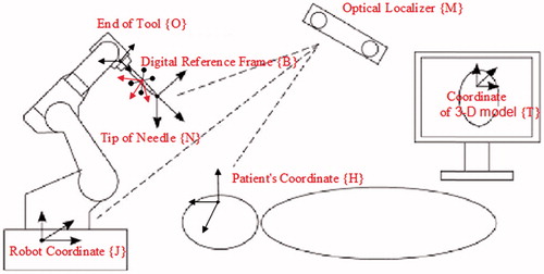
This article focuses specifically on the key technology of calibration between robot space and visual space to ensure accurate calibration between the robot space and visual space.[Citation11] If accurate calibration is achieved, the relative position and posture between the surgical instruments and the patient can be truly reflected. The robot will follow a path that has been previously planned by a doctor, allowing the end-effector of the robot to find the lesion center accurately. This ensures the success of the surgery and reduces the chance of injury to the patient.
This calibration includes conversion among the four coordinates: coordinate {M} of the optical positioning system, coordinate {J} of the robot base, coordinate {O} of the end of the robot tool center, and coordinate {B} of the digital reference frame. Their specific relationship of matrix transformation is expressed by EquationEquation (1)(1) :
(1)
Matrix JTM denotes the coordinate transformation in which coordinate {J} transforms to the coordinate {M}; matrix JTO shows the coordinate transformation in which coordinate {J} transforms to coordinate {O}; matrix OTB indicates the coordinate transformation in which coordinate {O} transforms to coordinate {B}; matrix MTB expresses the coordinate transformation in which coordinate {M} transforms to coordinate {B}. The robotic forward kinematics can solve out homogeneous transfer matrix JTO, and homogeneous matrix MTB displays the visual system in time. So it is crucial to ensure homogeneous transformation matrix MTO when we want to get accurate calibration of the relationship between robot space and visual space.
3. The automatic calibration method of linear and rotation
In order to address some of the issues with current calibration methods, the paper proposes a new method of automatic calibration of linear and rotation. In an experiment, the digital reference frame is fixedly connected with the end of the robot arm by a solid mechanical structure. The relationship between their coordinates is determined but unknown. Considering the particularity of the end of the tool center, the position calibration process uses the rotation method. The end of the tool center rotates around its own coordinate origin and uses nonparametric regression function to fit its spatial location by recording points. Meanwhile, orientation calibration uses the linear method. It is allowed to move along its own axis, and space orientation is obtained by fitting with the least squares principle.[Citation12] Finally, the calibration matrix is obtained by combining the position and posture. Path planning for the robot is also offered in order to reduce human error.[Citation13] The digital reference frame’s points of movement can be recorded through a certain frequency, allowing automatic calibrating.
3.1. Space orientation obtained by least squares principle fitting
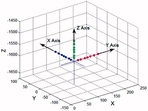
The end of the tool center of the robot moves along its own axis. CCD records the moving points of the digital reference frame sequentially, and each coordinate axis is fitted by the least squares principle.
The standard equation for the line is as follows:
(2)
Thus, x and y can be obtained from EquationEquation (3)(3) :
(3)
Where
In the equation, the space straight line is defined as the intersection of two nonparallel planes. Thus, the linear fitting of these two plane equations can be fitted separately. The square sum of the differences between the actual value and approximation solutions is obtained from EquationEquation (4)(4) as follows:
(4)
All of the partial derivatives can be set to 0 according to the principle of least squares method, as shown in EquationEquation (5)(5) :
(5)
The values of a, b, c, d are obtained from EquationEquation (6)(6) :
(6)
a, b, c, d can be plugged into EquationEquation (2)
(2) to acquire k1, k2 and k3. Then, the rotation matrix is obtained after normalization to fit the straight line equation. This gives the orientation of the end tool center in the optical locator coordinate system, as shown in .
Figure 2. Straight-line method fitting axes.
3.2. Coordinate origin obtained by nonlinear regression function fitting
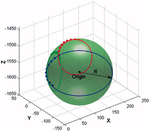
At first, the end of the tool center rotates around its own coordinate origin, and the origin of the digital reference frame’s position is recorded by the system of the optical localizer. Because of the unique positional relationship between the end of the tool center and the optical localizer, these recording spots form a sphere. The core of this sphere is the end of the tool center, and its radius is the distance between the origins of the coordinates. Supposing that the ball’s center in the optical locator coordinate system is a, b and c, and its radius is R, the parametric equation for the sphere is:
(7)
In order to get the best fitting line experimentally, EquationEquation (8)(8) must be satisfied:
(8)
The axis solving problem is translated into the extreme value of equation. Then, the nonlinear regression function from MATLAB can be used for fitting, as in EquationEquation (9)(9) :
(9)
The coordinates of the ball’s center and radius can be solved as shown in .
Figure 3. Rotation method fitting the origin.
Combined with the normalized position matrix obtained in this section, the homogeneous transformation matrix MTO can be obtained. The calibration matrix JTM is acquired by analyzing forward kinematics.
4. Path planning of the robot for the automatic calibration
To keep track of the digital reference frame, the trajectory of the linear and rotary automatic collimation is planned as in .
Figure 4. Robot path planning for the linear and rotary calibration.
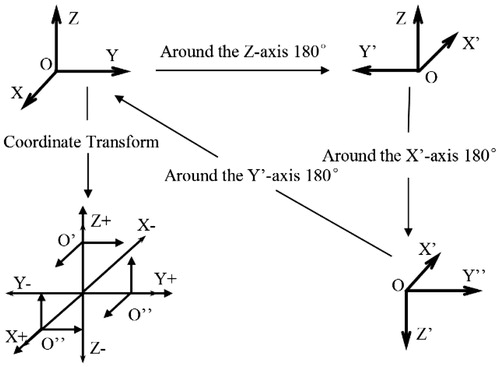
The end of the tool center rotates 180 degrees around each coordinate axis, and the position of the digital reference frame is collected by the optical localizer once every 100 ms. The system will use the nonlinear regression function in Section 3.2 to fit the origin of the coordinates after completion of the robot rotation. The robot naturally moves back to its initial position after rotation. Then, the end of the tool center coordinate of the robot moves a distance of 500 mm along each axis. Meanwhile, the position of the digital reference frame is collected by the system of the optical localizer once every 50 ms, and the system will use least squares principle as in Section 3.1 to fit each coordinate axis in the end. By this method, the pose of the end of the tool center in the system of the optical localizer can be acquired.
5. Experiment and analysis
In order to verify this calibration method, a surgical robotic system was built. Then an effective measuring method can be used to evaluate the calibration. Finally, in order to verify the accuracy and reliability of the automatic calibration method, a simulation experiment is conducted.
5.1. The surgical robotic system
The experimental prototype robot for the cranial and maxillofacial puncture surgery is built as shows.
Figure 5. Cranial and maxillofacial surgery prototype.
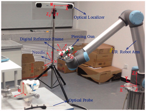
It’s mainly composed of: the UR robot arm, the optical tracking localizer, the piercing gun, the special device, and the digital reference frame. The system for cranial and maxillofacial puncture surgery makes use of the Canadian NDI company’s Polaris Vicra. The position accuracy is 0.25 mm RMS; the 95% confidence interval is 0.5 mm; the maximum frequency of the data updates is 20 Hz. In this experiment, the collaborative robot UR10 is used, and its repetitive accuracy is 0.1 mm.
5.2. The detailed process and accuracy results of calibration
In order to verify the accuracy of the calibration between robot space and visual space, several pose points in the surgical space are converted into the robot space through the calibration matrix in this experiment. Then, these points are solved through inverse kinematics of the robot, and the robot is controlled to move to the points. A laser tracker is used to detect the accuracy with which the robot reaches the target points, so the accuracy of the calibration method can be verified.
5.2.1. Verification method of calibration results
Needle tip N in cranial and maxillofacial puncture surgery is the control point in the robot’s trajectory, as shows. The robot’s position is the point’s position. This paper will use the deviation of position and posture to measure the accuracy of calibration. The pose of needle tip N in the laser tracker is X = [PT ϕ T].
Figure 6. The needle coordinate for cranial and maxillofacial surgery.
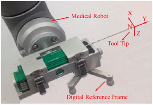
Initially, it is assumed that the pose of Needle tip N in the laser tracker is Xd = [Pd T ϕd T, and after coordinate transformation, needle tip N is guided to move toward the point. When the robot movement finishes, a laser tracker is used to measure the pose of the tip and note it down as Xr = [Pr T ϕr T ]. Δ P represents the translational positional deviation. This is calculated as |Δ P| = |Pd - Pr|, which gives the positional deviation between position Pd and position Pr. Δ ϕ represents the posture of the rotation deviation. Δ ϕ is given by Δ R = Rd Rr -1, which is the posture deviation between angle ϕd and angle ϕr. The comprehensive evaluation deviation is represented by Δ X = Δ PT Δ ϕ T.[Citation14]
5.2.2. The experimental results and analysis of calibration
In order to calibrate the linear rotation calibration method, 15 sets of pose points are given by the laser tracker in the surgical space, and then the needle tip N moves toward every point from another place. The accuracy of calibration is verified according to the error between the actual point and the target point. The results are shown in , and the error curves are given in .
Figure 7. Error curves of all experimental points: (A) the deviation of position; (B)the deviation of posture.
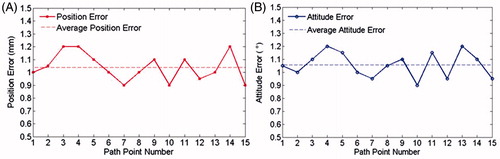
Table 1. Position and posture parameters of some given and measured points (unit: mm, degree).
The minimum position error is 0.87 mm and the minimum posture deviation is about 0.83 degrees, the mean position error is less than 1.05 mm and average posture deviation is about 1.1 degrees. The accuracy and precision of the optical localizer and the robot itself are the main factors which cause errors in measurement. On the whole, the calibration accuracy is high and smooth, and can meet the surgical requirements.
5.3. The simulated experiment of cranial and maxillofacial puncturing
The detailed process of the simulation experiment is shown in . A 3D head model was used in the place of a real head, mouse skin was used in the place of human skin, and meatballs were used in the place of a tumor focus. In this way, the Head-simulator was constructed. In order to reconstruct a 3D model of this Head-simulator, a CT scan is necessary. These scans help doctors to ascertain the shape and position of the tumor focus and plan a path to puncture. These were then mapped into the robot coordinate system, which was based on spatial coordinate transformation. The needle was punctured through the tumor focus according to the planned path. Finally, the head is reconstructed, and the actual final position of the needle is compared to its planned position. Thus, the calibration precision is obtained.
Figure 8. Simulated model of cranial and maxillofacial surgery.
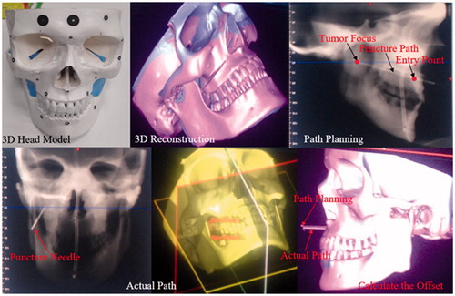
Five cases of needle biopsy surgery were analyzed. The experiment results are shown in , including the error of the entry position, the error of the target position and the error of the puncture direction. The minimum position error of the entry position and the target position were 0.87 mm and 0.83 mm, respectively. The minimum deviation of the puncture direction was about 0.89 degrees. The error curves are given in .
Figure 9. Pose error in the experimental needle biopsy surgery: (A) position error of entry position and tumor focus; (B) deviation in puncture direction.
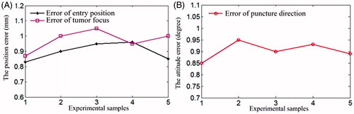
Table 2. Experiment contrast results of the planning and actual points (mm).
6. Conclusions
Considering the calibration accuracy and efficiency, the least squares method was used to fit each coordinate axis and nonlinear regression function to the origin of the coordinate. This allowed acquisition of the needle point position under the optical localization system by coordinate transformation, making automatic calibration possible. In this paper, the trajectory of the end tool center of robot is carried out in order to accelerate the speed of calibration. Experimental results have shown that the time needed for the process of the calibration is about one minute; and the calibration precision entirely meets the operation requirements. This opens up many possibilities for surgery navigation and calibration due to its favorable commonality and bright application prospects. In order to make the practical application in the calibration of clinical surgery navigation systems possible, the next phase of work will involve the design of a set of automatic calibration systems.
Disclosure statement
The authors declare no conflict of interest in this study.
Funding
This research was funded by National High-tech R&D Program of China (No. 2014AA041601, No. 2015BAF09B02) and China Postdoctoral Science Foundation (No. 2014M561338).
References
- Tian H, Yang P, Su C, et al. ICP registration technology based on the coordinate system direction fit. Int J Secur Appl. 2015; 9:47–56.
- De León-Cuevas S, Tovar-Arriaga, et al. Tool calibration with an optical tracker for skull milling. In: International conference on electronics, communications and computers, Puebla, Mexico; 2015. p.149–154.
- Besnard S, Khalil W. Identifiable parameters for parallel robots kinematic calibration. In: Proceedings of the IEEE International Conference on Robotics and Automation. Vol. 3. Seoul, South Korea: IEEE; 2001. p. 2859–2866.
- Tian H, Wu D, Wang J, et al. Visualization and real-time tracking technologies of the probe used in surgical navigation based on electromagnetic positioning. Jiqiren (Robot). 2011;33:59–65.
- Hu Y, Wei J, Wang T, et al. 3D morphing method based on Kriging algorithm for surgical navigation. In: Proceedings of the 34th Chinese Control Conference, Hangzhou, China, 2015, Technical Committee on Control Theory, Chinese Association of Automation, 28–30, 8372–8376.
- Chung GB, Kim S, Lee SG, et al. An image-guided robotic surgery system for spinal fusion. Int J Control Automat Syst. 2006; 4:30–41.
- Ma RQ, Development of the celiac minimally invasive surgery robotic executing system and research on its control algorithm. Harbin: Harbin Institute of Technology; 2013.
- Li C, Mechanism design and optimization of stereotactic operation robot for maxillofacial surgery. Beijing: Beijing Institute of Technology; 2015.
- Zhao XG, Yang TW, Han JD, et al. A review on the robot-assisted needle puncture technology. Chinese Sci Bull. 2014;58:20–27.
- Ma W, Zheng Y, Liu Y. Camera calibration using two concentric circles: linear approach. Opt Eng. 2009;48:053602–053602-6.
- Orlandi D, Sconfienza LM, Lacelli F, et al. Ultrasound-guided core-needle biopsy of extra-ocular orbital lesions. Eur Radiol. 2013;23:1919–1924.
- Zhang L, Zheng S, Chai X, et al. Optimization of projection matrix between cameras based on Levenberg–Marquardt algorithm. J Inf Comput Sci. 2015;12:1607–1614.
- Xu WF, Li LT, Liang B, et al. Workspace analysis of space 3Rrobot. J Astronaut. 2007;28:1389–1394.
- Smolskaitė L, Venskutonis PR, Talou T. Comprehensive evaluation of antioxidant and antimicrobial properties of different mushroom species. LWT-Food Sci Technol. 2015;60:462–471.