
Abstract
Robot-assisted systems can enhance the precision of surgical procedures, and have been widely used in minimally invasive surgery (MIS). This paper proposes the master–slave real-time control strategy for a novel surgical robot for MIS. The robot is equipped with two instrument manipulators and one laparoscope manipulator. The control strategy solves problems of kinematics transformation on consistency principle, intra-operative re-mapping and tremor attenuation in real-time. The kinematics model of slave instrument manipulators is established, and the master–slave control method in Cartesian space is proposed. Intra-operative re-mapping and real-time tremor attenuation algorithms are also proposed as auxiliary functions to improve surgical robot’s performance. The proposed methods are verified by respective experiments. Finally, animal experiment is performed to verify the correctness and efficiency of the control strategy in this research.
1. Introduction
Minimally invasive surgery has become the popular method for many surgical interventions in recent years. Unlike open surgery, minimally invasive surgery only needs small incisions in a patient’s body.[Citation1] Compared with the traditional open surgery, minimally invasive surgery has the advantages of small postoperative scar and short recovery time.[Citation2] In the past, however, surgeons have to use specialized tools with restricted flexibility and inferior visual feedback. Surgical robots overcome these weaknesses. Robot-assisted minimally invasive surgery (RMIS) system can improve precision and application range of minimally invasive surgery,[Citation3] and has broad market prospects in China.
The Da Vinci surgical robot system (Intuitive Surgical, USA) is the most successful commercially available product.[Citation4] The DLR MIRO system is a new versatile lightweight surgical robot, which assists the surgeon directly at the operating table without interference.[Citation5] The Raven system was developed by the University of Washington and originally designed for military use.[Citation6]
Versatile surgical robots in master–slave isomeric form have become the main stream now,[Citation7] for the reason that slave manipulators can be designed more suitable to specific needs of surgery, and the master equipment can be designed from ergonomic point of view. However, it is more difficult to control master–slave isometric robot because of problems such as workspace and kinematics transformation mismatch, and the real-time control demands that kinematics transformation, master–slave mapping and tremor attenuation must be accomplished in short period of time. Therefore, the employment of appropriate algorithms for these procedures is of great importance. In this paper, the real-time control strategy for our surgical robot is researched, and then related experiments are performed.
2. Robot system architecture
A novel versatile robot-assisted minimally invasive surgery system was developed by our group, which is focused on multi-kind of celiac surgeries. This master–slave isomeric system employs a novel remote center of motion (RCM) mechanism and has the characteristics of high stiffness and accuracy.[Citation8] The robot system consists of two main parts: main console and slave manipulators, as shown in and , respectively. Omega.7 (7 DOFs, Force Dimensions, Nyon, Switzerland) is selected as the master equipment, which is also adopted by DLR MIRO system. The first three parallel joints acquire position information of surgeon’s hand movement. The next three serial joints acquire orientation information. The last joint acquires the angle of fingers’ gripping movement.
Figure 1. Robot system architecture: (a) slave manipulators. (b) main console. (c) instrument manipulator. (d) master equipment.
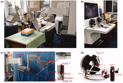
Slave manipulators are designed and are capable of performing complex operations. Three slave manipulators are used: one laparoscope manipulator and two instrument manipulators. All three manipulators are composed of joints in series, as shown in . Instrument manipulators have 9 DOFs and the laparoscope manipulator has the same first 6 DOFs of instrument manipulators. The first prismatic joint implements vertical movement of the whole manipulator in passive mode. Rotational joints 2 and 3 are also passive joints for preoperative position adjustment. Joints 1–3 are locked during surgical procedure. Rotational joints 4 and 5 implement fixed-point movement of the novel RCM mechanism. Prismatic joint 6 implements straight line motion of surgical instrument. Joints 4–6 cooperate to realize that the instrument could almost reach any position of the workspace. Four rotational joints 7–10 cooperate to precisely control the position and orientation of the instrument, to perform movements like gripping, cutting and pinching. Joints 9 and 10 cooperate to implement the gripping DOF. Hence, there are totally seven active joints with six DOFs and one gripping DOF in each instrument manipulator. In laparoscope manipulator, there are three active joints.
3. Master–slave real-time control strategy
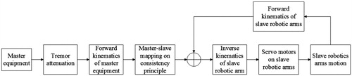
For efficiency and safety of minimally invasive surgery, the real-time control strategy must guarantee that the slave manipulator rapidly and accurately tracks the movements of master equipment and could never make unexpected actions. Surgeon manipulates master equipments, and the control system acquires position and orientation information of master equipments in real-time. Taking one instrument manipulator for example, the position and orientation matrix of master equipment is transformed to the matrix of slave manipulator through master–slave mapping on consistency principle (after hand tremor attenuation). The consistency principle demands that the position and orientation of master equipment should correspond with the position and orientation of instrument. Then, the control system solves inverse kinematics of instrument manipulator and sends the displacement of each joint to motor drivers on instrument manipulator. Servo motors drive the instrument manipulator to track the movement of master equipment. Meanwhile, control system acquires encoder information in real-time and calculates forward kinematics of instrument manipulator to implement closed-loop control. The visual feedback is acquired by the laparoscope and displayed in 3D screen, which enhances surgeon’s immersion in surgical procedure. The structure of real-time control strategy is shown in .
Figure 2. Real-time control strategy structure.
In order to accomplish minimally invasive surgery, the robot system should possess some auxiliary functions such as intra-operative re-mapping and hand tremor attenuation.
3.1. Master-slave control method in Cartesian space
Master–slave control method in Cartesian space has the characteristics of intuition and accuracy, which is at the cost of more difficulty than control method in joint space. On consistency principle, the method can be expressed as:
(1)
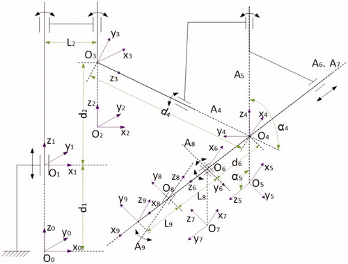
where STT is the homogeneous transformation matrix from slave manipulator coordinate to tool coordinate, LST is the transformation matrix from laparoscope coordinate to slave manipulator coordinate, MHT is the transformation matrix from master equipment coordinate to handle coordinate, and DMT is the transformation matrix from displayer coordinate to master equipment coordinate. Usually MHT is the input and STT is the output. All these four matrixes should be calculated from or to joint displacements through kinematics transformation to implement the control method. For master–slave isomeric robot, the kinematics transformation is a crucial part. Coordinate systems on instrument manipulator are built as shown in . The gripping is not taken into the account of total DOFs.
Figure 3. Coordinate system on instrument manipulator.
The D–H parameter table of instrument manipulator is shown in .
Table 1. The link parameters and the joint variables of instrument manipulator.
The forward kinematics is simple and can be expressed as:
(2)
where A1–A9 are joint matrixes, respectively, and are all known.
The inverse kinematics of slave manipulators is relatively complicated and there is no optimal algorithm. A common method is to assume that wrist joints only affect the orientation of instrument, which is to assume that the axes of wrist joints intersect at one point.[Citation9] This assumption is based on the small size of wrist joints, but such method essentially introduces error which is difficult to compensate. Some other methods have to solve pseudo inverse Jacobean matrix, which cost too much calculation to meet the real-time requirements.[Citation10]
According to the structural features of instrument manipulator, the axes of joints 4–6, not wrist joints, interact at one point, so that the manipulator does not conform to the Pieper principle. However, if judging from inverse direction, joints 4–6 are wrist joints and joints 7–10 are manipulator joints. There is closed-form solution, so we inverse the input matrix to get the closed-form solution.
This algorithm can get the analytic solution at less calculation cost, because there is no need for error compensation or solving inverse Jacobean matrix, and choosing proper anti-trigonometric functions according to the motion range of each joint can avoid the multi-solution problem. Trigonometric function calculation is very fast for modern computer, so this algorithm is applicable for real-time control.
0T9 = STT is the input matrix. Because joints 1–3 are locked during surgical procedure, the homogeneous transformation matrix from reference coordinate system to joint 3 coordinate system, 0T3 is known. Left multiply 0T3 - 1 and get (3):
(3)
where 0T3 - 1 ċ 0T9 is known, so (0T3 - 1 ċ 0T9)- 1 is known and can be expressed as
(4)
Transform EquationEquation (3)(3) and get (5)
(5)
From (4) and (5), there are equations as follows:
(6)
Corresponding items on both sides of (5) are equal. Find simple pairs only containing θ8, θ9 and d6.
(7)
From (7),
(8)
if θ9 ≠ 0, then
(9)
if θ9 = 0, then
(10)
Transform EquationEquation (5)(5) and get (11)
(11)
0T3 - 1 ċ; 0T9 ċ (A8 A9) - 1 is known now. Corresponding items on both sides of (11) are equal. Find simple pairs:
(12)
(13)
where
Right multiply A7 - 1 on both sides of (11) and get (14)
(14)
From (14),
(15)
where
From all known angles, the homogeneous transformation matrix from reference coordinate system to RCM, T5 is known, and the homogeneous transformation matrix from reference coordinate system to first wrist joint, T6 is also known. T5 and T6 can be expressed as:
(16)
(17)
So, the displacement of joint 6 can be solved as:
(18)
Now the whole set of active joint displacements is solved. Each of the above anti-trigonometric function only yields one solution within the motion range of each joint, which avoids the multi-solution problem. By using the analytic solution, the master–slave control method in Cartesian space is established.
3.2. Intra-operative re-mapping
When master equipment moves close to the boundary of workspace or in uncomfortable operation area, the master–slave mapping should be cut off until master equipment is adjusted to appropriate operation area, with the surgical instruments keeping still, which enhances the flexibility of surgical robot. On consistency principle, the position and orientation of master equipment after adjustment should be considered corresponding to the position and orientation of slave manipulator after adjustment (it actually does not move). The whole procedure is just like lifting mouse from desk and putting it down in a new position. In order to implement this function, position and orientation increments of the master equipment are adopted as the input of mapping, while situations for position and orientation are a little different.
As the position is in Cartesian linear space, reference position is simply substituted with acquired new one as follows:
(19)
where HM P0 is the reference hand position in master equipment coordinate system, HM Paquired is the position acquired after adjustment, HM P(t + 1) is the position acquired on t + 1 moment after adjustment, d(HM P(t + 1)) is the position increment on t + 1 moment, d(HM P(t + 1)) is the tool position increment in slave manipulator coordinate system mapped from d(HM P(t + 1)), TS P(t) is the tool position on t moment, and TS P(t + 1) is the tool position on t + 1 moment.
Reason for orientation is a little tricky because orientation is not in linear space. Inverse kinematics of master equipment is solved to get three joint angles corresponding to the slave manipulator orientation. Subtract these three angles from three angles acquired after adjustment would be the new reference angles as follows:
(20)
where [α β η]0 is the set of three reference angles, [α β η]acquired is the set of angles acquired after adjustment and before re-mapping, [α β η]solved is the set of angles corresponding to the slave manipulator orientation after adjustment, [α β η]t + 1 is the set of angles acquired on t + 1 moment, [α β η]'t + 1 is the set of angles for forward kinematics, HM R(t + 1) is the orientation matrix calculated from [α β η]'t + 1, and TS R(t + 1) is the tool orientation matrix in slave coordinate on t + 1 moment.
3.3. Real-time tremor attenuation
Physiological tremor is an involuntary, roughly sinusoidal component inherent in normal human hand motion. Physiological hand tremor lies in the band of 8–12 Hz and has an amplitude of 50 μm in each principal axis, which has resulted in imprecision in surgical procedures.[Citation11] For RMIS system, surgeons’ hand motion should be amplified to refine the surgical operation, which also amplifies the tremor, which makes the tremor problem even worse. Linear filters can attenuate tremor but their inherent time delay is a weakness for real-time control.[Citation12] Real-time tremor attenuation algorithm must distinguish voluntary signal and involuntary tremor in real time. According to the hand tremor feature and computer-processing ability, the band-limited multiple Fourier linear combiner (BMFLC) is adopted as the real-time tremor attenuation algorithm for our RMIS system.[Citation13]
Tremor is amenable to the Fourier series model because of its roughly periodic feature. The tremor signal can be estimated by adapting amplitude and phase of some sinusoidal signals in different reference frequencies. As tremor is about in the range of 8–12 Hz, a range of interest (f1–f2) is set. Divide the range into N divisions and choose division points as reference frequencies, which means there are N + 1 reference signals summing up to fit the tremor signal. The LMS algorithm is used to update the weights. BMFLC can be written as follows:
(21)
where N is the number of divisions and N= (f–f0)G, Sk is the input signal, ɛk is the estimated value of Sk, Wk is the adaptive weight vector and μ is an adaptive gain parameter. If μ is too small, the convergence progress will be too slow, and if μ is too big, the sequence will be divergent.
4. Experiments and discussion
4.1. Motion trajectory tracking experiment
In order to verify the correctness of master–slave real-time control strategy, touching and positioning task was performed continuously by the robot system on 3D positioning training module. The training module is shown in . In the experiment, operator manipulated the surgical instrument end-effector to touch points from A to F in turn and recorded the trajectories of both master equipment and surgical instrument end-effector. The trajectories are shown in . It should be noted that the trajectory of master equipment has been mapped to be in slave manipulator workspace.
Figure 4. Motion trajectory tracking experiment: (a) training module; (b) two trajectories in manipulator workspace.
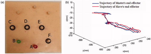
As shown in , the control strategy could repeat surgeon’s hand motion in real-time. There was a deviation between two trajectories. The main reason for this is the slave manipulator joints’ return difference. Because the instrument is driven by steel wire, the elasticity of steel wire also contributes to the error. The tiny time delay of control system is another cause for the error. Therefore, the effects of mechanical return difference and steel wire elasticity should be focused in the future.
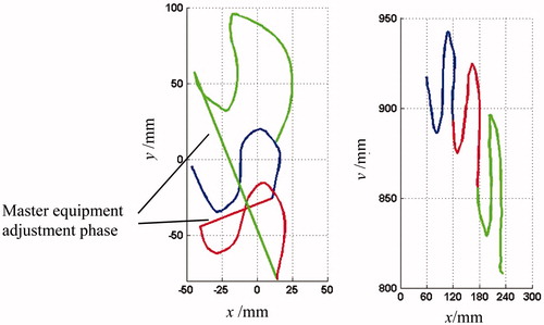
4.2. Intra-operative re-mapping experiment
For the sake of illustration, we focus on master and slave trajectories’ projection curves in the x–y plane. The experiment procedure is shown in . When master equipment moved along the blue trajectory, slave manipulator end-effector tracked the movement and its trajectory was also marked with blue. Then cut off master–slave mapping, adjusted master equipment and re-mapped. In this time, the master equipment moved along the red trajectory and the slave trajectory was marked with red. Re-mapped again and marked two trajectories with green. As shown in , regardless of the adjustment of master equipment, the surgical instrument end-effector resumed the movement from the stop point, which guaranteed the continuity of its trajectory.
Figure 5. Intra-operative re-mapping of master–slave control.
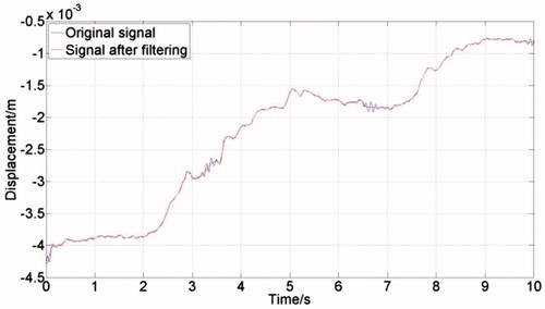
4.3. Tremor attenuation experiment
Computer processing ability should also be considered when filtering the input signal acquired by master equipment with BMFLC algorithm. In order to ensure the real-time performance of whole system, not only the sampling frequency of master equipment cannot be too fast, but also the frequency interval in BMFLC algorithm cannot be too close. An industrial computer (ARK-3510, Advantech) was employed for the experiment. QNX real-time operating system was used to acquire master equipment (Omega.7, Force Dimensions) output data in real time. The sampling frequency was set to be 1KHz. The parameters were set to be f0 = 5, f = 15, L = 20, μ = 0.001. The outcome of the experiment is shown in . Tremor signal in about 10 Hz was filtered and voluntary signal in low frequency was reserved.
Figure 6. Experiment result of tremor attenuation.
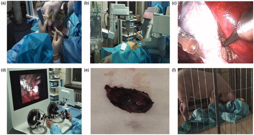
4.4. Animal experiment
Surgeons could adjust the position and gesture of instruments based on valuable experience. Actually, with the visual feedback and master equipment manipulation, surgeons themselves make up an important part of closed-loop master–slave control. Therefore, the robot system should be accurate and intuitive to interact with surgeons. Therefore, positioning accuracy of slave manipulator instrument plays an important role in master–slave robot system. Absolute positioning accuracy and repeat positioning accuracy of slave manipulators are 1.3958 and 0.2443 mm, respectively, which are measured by a 3D motion capture system (Optotrak, NDI). That satisfies the accuracy requirements of master–slave control for surgical system.[Citation14]
In order to verify the stability and maneuverability of our surgical robot, an animal cholecystectomy experiment was carried out on a pig operated by professional surgeons. The pig weighted about 30 kg. The anesthetist anesthetized the pig 15 minutes before the surgical procedure. Then, we had preoperative preparations, including fixing the pig on the table, establishing incisions for instruments and setting up robot configuration. The operating time was close to 2 hours. The pig awoke about 30 minutes after surgery and 10 hours later began to eat. The experiment situation is shown in . The surgical robot can perform the resection precisely based on surgeon’s manipulation, and the intra-operative re-mapping and tremor attenuation auxiliary functions also worked well. The above results reveal that the proposed real-time control method is correct and effective.
Figure 7. Animal experiment pictures: (a) pre-operative preparation and anesthesia; (b) slave manipulator picture; (c) intraoperative endoscopy image; (d) main console picture; (e) resected gallbladder; (f) pig after surgery.
5. Discussion and conclusion
With the purpose of equipping surgeons with manipulators to refine surgical procedures and reduce the workload, a new master–slave real-time control strategy for a RMIS system in master–slave isomeric form was proposed. The problems of kinematics transformation on consistency principle, intra-operative remapping and tremor attenuation in real-time were solved. The experiment results shown in indicated that master–slave control method in Cartesian space can realize the consistency principle. Results shown in and indicated respectively that intra-operative re-mapping and tremor attenuation auxiliary functions could work well. Animal experiment indicated that our robot system with the proposed master–slave control strategy can perform in vivo surgical tasks. Therefore, master–slave control strategy in Cartesian space is correct and effective. This control strategy can be specialized for this kind of surgical robots or applied in other robotics industry with master–slave control and high demand for real time.
In the future, we will focus on the maneuverability and safety of surgical robot during the surgery. After further improvement on robot’s performance, we will conduct some clinical trials.
Disclosure statement
The authors report no conflicts of interest. The authors alone are responsible for the content and writing of this article.
Funding
This work was supported by the National High Technology Research and Development Program of China (‘863 Program’) (Grant No. 2012AA041601), the National Natural Science Foundation of China (Grant No.61305139), Self-Planned Task (No. SKLRS201406B) of State Key Laboratory of Robotics and System (HIT), the Fundamental Research Funds for the Central Universities (Grant No. HIT. NSRIF. 2013052).
References
- Valero R, Ko YH, Chauhan S, et al. Robotic surgery: history and teaching impact. Actas Urol Esp (English Edition). 2011;35:540–545.
- Tavakoli M, Patel RV, Moallem M, et al. Haptics for teleoperated surgical robotic system. Singapore: World Scientific publisher; 2008.
- Kim U, Lee DH, Yoon WJ, et al. Force sensor integrated surgical forceps for minimally invasive robotic surgery. IEEE T Robot. 2015;31:1214–1224.
- Turchetti G, Palla I, Pierotti F, et al. Economic evaluation of da Vinci-assisted robotic surgery: a systematic review. Surg Endosc. 2012;26:598–606.
- Hagn U, Nickl M, Jörg S, et al. The DLR MIRO: a versatile lightweight robot for surgical applications. Ind Robot. 2008;35:324–336.
- Rosen J, Lum M, Sinanan M, et al. Surgical Rrobotics: Raven: developing a surgical robot from a concept to a transatlantic teleoperation experiment. New York: Springer; 2011.
- Yu L, Wang Z, Yu P, et al. A new kinematics method based on a dynamic visual window for a surgical robot. Robotica. 2014;32:571–589.
- Niu GJ, Pan B, Fu YL, et al. Optimization and preoperative adjustment design of remote center motion mechanism for minimally invasive surgical robot. Robot Biomimet. 2015;2:1–14.
- Ma RQ, Wu DM, Yan ZY, et al. Research and development of microinstrument for laparoscopic minimally invasive surgical robotic system. Paper presented at: IEEE International Conference on Robotics and Biomimetics; 2010 Dec 14–18; Tian Jing, China.
- Feng M, Fu Y.l, Pan B, Liu C. Development of a medical robot system for minimally invasive surgery. Int J Med Robot Comp. 2012;8:85–96.
- Riviere CN, Rader RS, Thakor NV. Adaptive canceling of physiological tremor for improved precision in microsurgery. IEEE Trans Biomed Eng. 1998;45:839–846.
- Prochazka A, Elek J, Javidan M. Attenuation of pathological tremors by functional electrical stimulation. I: Method. Ann Biomed Eng. 1992;20:205–224.
- Veluvolu KC, Tan UX, Latt WT, et al. Bandlimited multiple Fourier linear combiner for real-time tremor compensation. Paper presented at: Annual International Conference of the IEEE Engineering in Medicine and Biology Society; 2007 Aug 23–26; Lyon, France.
- Pan B, Research on detached medical robot for minimally invasive surgery and its control method. Harbin: Harbin Institute of Technology; 2016.