
 ?Mathematical formulae have been encoded as MathML and are displayed in this HTML version using MathJax in order to improve their display. Uncheck the box to turn MathJax off. This feature requires Javascript. Click on a formula to zoom.
Abstract
Minimally invasive procedures are rapidly growing in popularity thanks to advancements in medical robots, visual navigation and space registration techniques. This paper presents a precise and efficient targeting method for robot-assisted percutaneous needle placement under C-arm fluoroscopy. In this method, a special end-effector was constructed to perform fluoroscopy calibration and robot to image-space registration simultaneously. In addition, formulations were given to compute the movement of robot targeting and evaluate targeting accuracy using only one X-ray image. With these techniques, radiation exposure and operation time were reduced significantly compared to other commonly used methods. A pre-clinical experiment showed that the maximum angle error was 0.94° and the maximum position error of a target located 80mm below the end-effector was 1.31mm. And evaluation of the system in a robot-assisted pedicle screws placement surgery has justified the accuracy and reliability of proposed method in clinical applications.
Introduction
Minimally invasive procedures make it possible for surgeons neither to look directly at nor to touch the tissues of organs on which they operate [Citation1]. Unfortunately, obstruction of visual field dramatically increases the difficulty of these surgeries [Citation2]. Nowadays, a number of special techniques have been designed to deal with this case [Citation3,Citation4]. Among these techniques, medical robots, usually aided by navigation tools, serve to position a target with a great degree of accuracy [Citation2,Citation5]. Meanwhile, fluoroscopy units (C-arms), as most commonly used equipment in the modern operating room, can provide precise and real-time intraoperative two-dimensional (2-D) visualization. The combination of these two techniques dramatically improves the applications of minimally invasive surgery [Citation6–9].
Implementations of the fluoroscopy guidance can be categorized under two titles: calibrated methods and uncalibrated methods [Citation10]. The calibrated methods tend to compose two critical registration steps: fluoroscopy calibration and robot to image-space calibration [Citation11]. In the former, the intrinsic and extrinsic parameters of an imager are usually calculated by placing a phantom, on which several fiducial markers distribute, in the field of view (FOV) of a fluoroscopy. The robot to image-space is registered with at least three points whose position are known both in the robot frame and the image-space frame [Citation12]. After the registration, a point on an X-ray image can determine a ray connecting the X-ray source and the point on the image plane [Citation13,Citation14]. Although this method computes the exact position of a target, the whole registration process is time-consuming and tends to have a high radiation dose. Furthermore, due to the lack of C-arm position and orientation encoding information, imagers have difficulty to switch between two specific positions. As a result, a biplanar fluoroscopy is favored or even necessary in this method [Citation15]. However, the huge volume and high cost lead biplanar imagers only used in some special operating room.
Another kind of method is uncalibrated or visual servoing based [Citation16–18]. Requiring no additional sensors, no stereotactic equipment, and no prior calibration, these methods can finish 3 D alignment of a target point and a needle using multiple X-ray images collected from two dissimilar views. Nonetheless, it’s usually taking at least 12 iterations to complete one positioning [Citation17] and 6 * (n + 1) iterations for n targets alignments [Citation19]. These multiple iterations increase radiation exposure and operating time significantly, especially for some multi-points targeting tasks such as pedicle screws placement surgery. In addition, one common feature of these systems is that robots orient a needle in space while maintaining the location of one specific point (needle entry point), however, in some applications, it is the direction of the needle other than the entry point makes more sense.
To solve the problems mentioned above, our study extends the calibrated methods and proposes a robot-assisted targeting approach featuring low radiation and high efficiency. We will design a particular end-effector to perform the fluoroscopy calibration and robot to image-space registration simultaneously and give the formulations of the robot movement for aligning a specific point in the view of a uniplanar fluoroscopy. We will also develop a method to assess alignment accuracy by using single X-ray film. For evaluation, this method will be implemented both in the pre-clinical experiment and clinical experiment of pedicle screws placement surgery.
Materials and methods
System overview
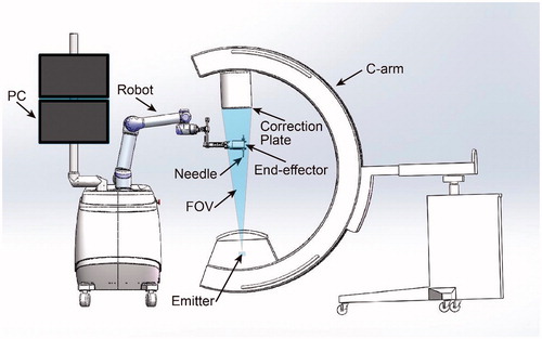
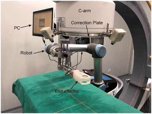
The system () comprises of a 6 degrees of freedom (DOF) robot, a digital C-arm, an end-effector, an image correction plate and a PC for robot control and image processing. The end-effector, used to position a needle, is always in the FOV of the C-arm. The correction plate mounts on the imager intensifier of the C-arm.
Figure 1. System structure.
End-effector design
Structure of the designed end-effector (): An indicator line and two different size circles, made by radiopaque materials, are embedded in a radiolucent hollow housing. The center holes of the two circles are used to place a multi-stage guide sleeve adapted to different size needles. Definition of the tool coordinate system (TCS) of the robot (): The tool coordinate point (TCP) is located at the center of the small circle. The x-axis is collinear with the indicator line and the z-axis is collinear with the line connecting the centers of the two circles with the direction from the center of the big circle to the center of the small circle. The transform matrix from TCS to the robot is calibrated after the end-effector mounts on the robot, and the result is stored in the robot controller. The quick connector guarantees the end-effector and robot have a reliable and convenient installation.
Figure 2. The structure of the end-effector.
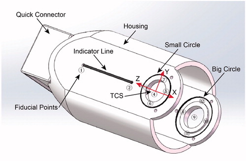
To calibrate the pinhole model of an imager, at least 6 points whose positions are known in a world coordinate system are needed. The registration accuracy will improve if more such points are provided [Citation20]. According to this, we have defined 12 fiducial points, which are not separative metal balls but geometric feature points distributed on the line and circles, on the end-effector (). This strategy makes sure that fiducial points can be recognized and determined relative position easily using basic image process techniques like Hough transform. In addition, such feature also avoids the registration failure caused by the overlapping of the fiducial points and the points on the correction plate on X-ray images. Moreover, the usage of the two circles allows to assess targeting accuracy from just one X-ray image (this will be elaborated later). When the end-effector is used to position, it is a good practice to arrange the big circle closer to the image emitter which makes sure the big circle will have an even bigger projection on X-ray film. This principle would ensure that the program can always correctly recognize the two circles and the fiducial points distributed on them.
Registration and targeting
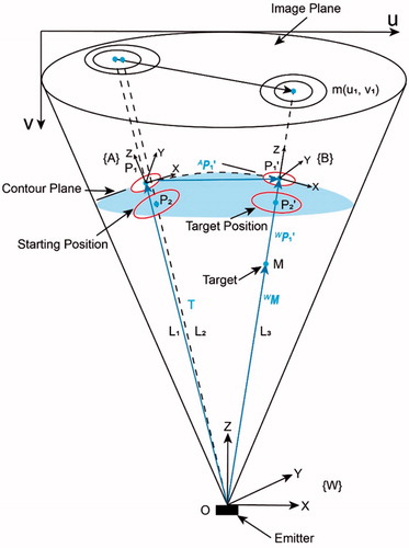
shows the movement of the end-effector in the FOV of a fluoroscopy before and after targeting. In the starting position, the projection of the circles is two non-concentric ellipses [Citation21], because the connecting lines () between the emitter and each center of the circles are not collinear. The TCS in this position is denoted as {A}.
,
are centers of the small circle and big circle respectively. In the target position, the centers of the two circles (
), the target M and the emitter are 3 D aligned, as a result, the two projection ellipses are concentric with the projection of target m as the common center. In this position, the TCS is represented by {B}. Note that the distance between the center of the small circle and emitter in each targeting process is constant. This gives the ability of defining an appropriate distance manually between the end-effector and patients in the initial position while maintaining it after the movement. The imager space is denoted by {W}.
Figure 3. The movement of the end-effector in the FOV of a fluoroscopy.
According to the mathematical model of a pinhole camera [Citation22], for a space point in the world coordinate system, the projection point
on the image can be formulated as (image distortion is not considered):
(1)
(1)
where are pixel scaling on the image base and
are image center. These four parameters in matrix
are called intrinsic parameters of an imager, since they are only determined by C-arm internal structure. The matrix
is the transformation matrix from world coordinate system to camera coordinate system. Inside,
is a rotation matrix and t is a three-dimensional translation vector. The six independent parameters in the matrix
compose the extrinsic parameters of the imager.
To extract precise positions of each point, the image is processed as follows: firstly, a Gaussian filter is applied to reduce image noise. Secondly, the Canny edge detection is used to obtain edge contours of circles and line. Then, a curve fitting algorithm serves to determine the mathematical expression of these geometrical elements [Citation23,Citation24]. Finally, coordinates of geometric feature points are obtained by solving simultaneous equations.
When the calibration has been done, the matrix in EquationEquation (1)
(1)
(1) denotes the transformation matrix from {A} to {W}. For a chosen target point
on the image coordinate, the vector
in the image-space is given by:
(2)
(2)
where is the
coordinate of the M in the image-space.
Given the vector ,
are collinear, the
can also be denoted by EquationEquation (2)
(2)
(2) with the
computed by:
(3)
(3)
The point in the {A} is determined by:
(4)
(4)
Using the , the TCP can move to the right position directly. It is worth noting that the target orientation of the end-effector is not unique as long as the z axis has the right direction. A minimal rotation from the starting position to the target position is performed in this method. The rotation axis
and the angle
are obtained respectively by:
(5)
(5)
where ,
are z axis of frame {A} and {B} respectively.
The robot end-effector movement can be given by translation and rotation denoted by axis-angle representation:
(7)
(7)
Evaluation
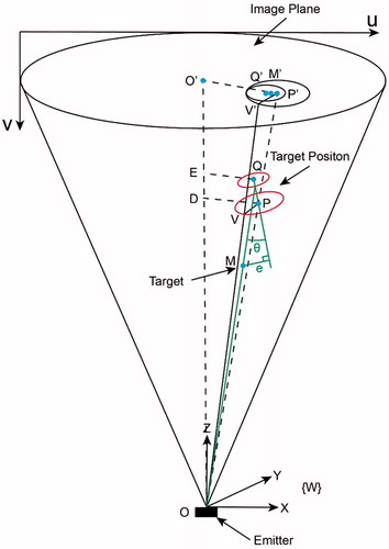
The aim of this section is to evaluate the alignment accuracy by using one X-ray image. shows the state when the robot has finished the alignment. In this figure, Q and P are the centers of the small circle and the big circle respectively. is aligned with the z-axis of the image-space frame. Note that
is not necessarily the center of the image.
, a radius of the big circle, is parallel to the image plane.
and
are both parallel to the image plane. The angle error
is defined by the space angle between
and
. When the depth of a target point is known, the position error
can be represented by the distance between the point M and the line
. To get these errors, the exact position of Q and P need to be computed firstly.
Figure 4. The state when the alignment finished.
Using these two similar triangles relationship:
(8)
(8)
We have the following expression:
(9)
(9)
Given the source to intensifier distance of the C-arm is relatively far and the circles are usually located in the central region, the can be represented by the semi-major axis of the big projection ellipse
multiplying an image scaling factor
.
is represented by the actual radius of the big circle
. Extending all these relationship to the small circle, the following relationship is obtained:
(10)
(10)
where is the radius of the small circle and
is the semi-major axis of the small ellipse on the X-ray image.
In addition, the is determined by the center distance of the two circles
:
(11)
(11)
According to the conditions (10) (11) and EquationEquation (2)(2)
(2) , we can compute the exact position of the points Q and P in the {W}. The formulations of
and
are then written as:
(12)
(12)
Experiment and result
For the evaluation, the system was assembled for the proposed method. The robot is the UR5 (UNIVERSAL ROBOTS). The digital C-arm has an approximate source to intensifier distance of 1 meter and an intensifier diameter of 36 cm. The system was tested for accuracy and reliability using specially derived experiments and then clinically validated for pedicle screws implement.
Pre-clinical validation
The initial evaluation of the method was done in a laboratory without the participation of subjects (). Ten experiments were done following below procedures:
Figure 5. Pre-clinical experiment setup.
Set the C-arm in a random position and orientation.
Teach the robot end-effector to an appropriate position. For consistency with clinical applications, the end-effector is 25 cm below the image intensifier.
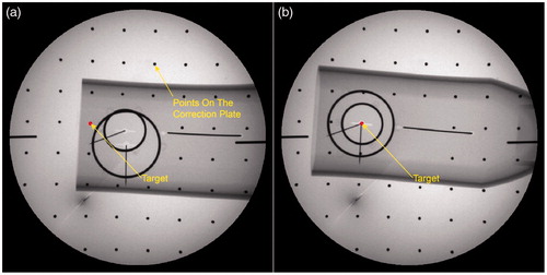
Take one X-ray film ().
Figure 6. Fluoroscopy images of end-effector in pre-clinical validation. a) The fluoroscopy image before alignment; b) The fluoroscopy image after alignment.
Correct the image distortion by algorithm using the projection of equally spaced balls on the correction plate. The fiducial points on the end-effector were then extracted automatically and further used to implement the registration from robot to image-space. Note, the whole step was done automatically without any interaction of the operator and the time spent is negligible.
Select a target point on the PC monitor, and the program then computed the movement parameters of the robot.
The robot moved to the target position and finished the 3D alignment.
Take another X-ray film ().
Record the position of the two centers of the projection ellipse and the target point on the image and evaluating the accuracy of the alignment.
shows the experimental data of the 10 alignments. The maximum angle error between the central axis of the end-effector and the targeting ray is 0.94°. The average position error of the points located 80 mm below the end-effector is 1.31 mm which satisfies the needs of even certain demanding surgeries. The average time to complete one targeting and evaluation is 3.5 minutes, including the position of the C-arm and robot. The results of the experiment trails enabled us to confidently proceed with clinical trials.
Table 1. The experiment data of pre-clinical experiments.
Clinical application
To evaluate the feasibility in clinical applications, this method was implemented as a critical step in the robot-assisted pedicle screws placement surgery. In the setup, the robot and C-arm were put on sterile covers and placed on the same side of the operating bed. The end-effector was sterilized by ultraviolet considering the material is not resistant to high temperatures. The patient was placed in a prone position under total anesthesia.
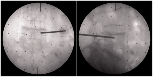
After the preparation phase, the surgeon planed the needle insertion path in the program using anteroposterior (AP) fluoroscopic image and pre-scanned CT data, and rotation angles of the C-arm from the AP to axial position (in this view, the projection of the needle would be a point) were calculated. The C-arm was then adjusted to a desired orientation manually according to these values. Next, step 2–7, described in the pre-clinical evaluation, were carried out sequentially to finish the needle targeting and alignment evaluation. One group of fluoroscopic images before and after alignment are shown in . After rotating away the C-arm, the surgeon installed the multi-stage sleeve and performed the pedicle screw placement (). The separation of the positioning process and drilling process ensures that the needle may not be inadvertently inserted during the orientation stage and accidental reorientation may not occur during needle insertion. shows that the surgeon verified needle targeting and depth of the insertion using other C-arm views.
Figure 7. Fluoroscopy images of end-effector in clinical application. a) The fluoroscopy image before alignment; b) The fluoroscopy image after alignment.
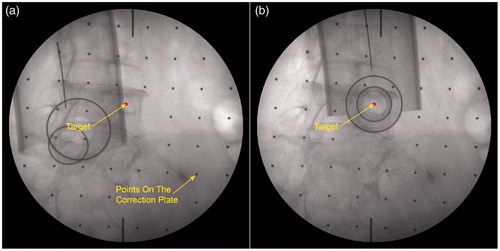
Figure 8. The surgeon finished the needle placement after the targeting.
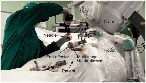
Figure 9. Verifying the accuracy of pedicle screw placement using the AP and lateral fluoroscopic images.
During the operation, A total of 30 X-ray images were taken with an average of 7.5 to finish individual placement of pedicle screw. Most of these were used to determine the standard AP and assess the depth of inserted needles. The radiation exposure was significantly reduced as compared to the other fluoroscopy guidance approach. Thanks to the simplification of the method, the actual implantation time of the 4 pedicle screws were reduced to 35 minutes. After the evaluation, the surgeon determined that all 4 pedicle screws were successfully implanted with highly accepted accuracy.
Discussion
In our study, we have presented a robot-assisted targeting method under C-arm fluoroscopy guidance based on the calibration of the imager. By using a specially designed end-effector, the imager calibration, the registration from the robot to image-space and the alignment of a target can finish automatically with just one X-ray image. The accuracy of the positioning can be evaluated directly by using another X-ray image with the same view. With these techniques, the radiation exposure and operation time have been reduced significantly. All surgeons need to do is adjusting the C-arm to a desired orientation and choosing a target point on the image.
Additionally, owing to simplification of the operation steps, the accuracy of the targeting has been improved. The pre-clinical experimental demonstrates that the maximum angle error was 0.94° and the maximum position error of a target located 80 mm below the end-effector was 1.31 mm. The evaluation in the clinical experiment of the pedicle screws placement has shown that all 4 screws were successfully implanted with the accuracy highly accepted by the surgeon.
Conclusion
A robot-assisted positioning approach was developed to improve placement accuracy of needle insertion. Design of the special end-effector and formulations for targeting and accuracy evaluation were elaborated. The results of both pre-clinical experiment and clinical application show that this method can improve positioning accuracy and reduce operation time and radiation exposure dramatically. Another feature of this method is that the orientation of the C-arm imager other than entry point determines the direction of the inserted needle. This feature makes the method ideal for a range of surgeries in which the needle path can be pre-planned by preoperative data like CT or determined by surgeon experience. To sum up, the presented robot-assisted system shows outstanding advantages in improving the accuracy and efficiency during pedicle screws placement. Additional clinical cases in such surgeries are scheduled in the near future.
Disclosure statement
No potential conflict of interest was reported by the authors.
Additional information
Funding
References
- Mack MJ. Minimally invasive and robotic surgery. JAMA. 2001;285:568–572.
- Dogangil G, Davies BL, Rodriguez y Baena F. A review of medical robotics for minimally invasive soft tissue surgery. Proc Inst Mech Eng H. 2010;224:653–679.
- Wang W, Shi Y, Goldenberg AA, et al. Experimental analysis of robot-assisted needle insertion into porcine liver. BME. 2015;26:S375–S380.,
- Wang WD, Zhang P, Shi YK, et al. Design and compatibility evaluation of magnetic resonance imaging-guided needle insertion system. J Med Imaging Health Inform. 2015;5:1963–1967.
- Barbash GI, Glied SA. New technology and health care costs-the case of robot-assisted surgery. N Engl J Med. 2010;363:701–704.
- Yaniv Z, Joskowicz L. Precise robot-assisted guide positioning for distal locking of intramedullary nails. IEEE Trans Med Imaging. 2005;24:624–635.
- Bernardes MC, Adorno BV, Poignet P, et al. Robot-assisted automatic insertion of steerable needles with closed-loop imaging feedback and intraoperative trajectory replanning. Mechatronics. 2013;23:630–645.
- Ringel F, Stüer C, Reinke A, et al. Accuracy of robot-assisted placement of lumbar and sacral pedicle screws: a prospective randomized comparison to conventional freehand screw implantation. Spine. 2012;37:E496–E501.
- Yoon HM, Cho H, Park K, et al. Method for C-arm based guide needle insertion assistant system for endoscopic disc surgery. Korean J Comput Des Eng. 2015;20:263–268.,
- Yao J, Taylor RH, Goldberg RP, et al. AC‐arm fluoroscopy‐guided progressive cut refinement strategy using a surgical robot. Computer Aided Surgery. 2000;5:373–390.,
- Laudato PA, Pierzchala K, Schizas C. pedicle screw insertion accuracy using O-arm, robotic guidance, or freehand technique. Spine. 2018;43:E373–E378.
- Schreiner S, Anderson JH, Taylor RH, et al. A system for percutaneous delivery of treatment with a fluoroscopically-guided robot. In: CVRMed-MRCAS'97. Berlin, Heidelberg: Springer; 1997. p. 747–756.
- Czerny C, Eichler K, Croissant Y, et al. Combining C-arm CT with a new remote operated positioning and guidance system for guidance of minimally invasive spine interventions. J Neurointervent Surg. 2014;7:303–308.
- Bzostek A, Schreiner S, Barnes AC, et al. An automated system for precise percutaneous access of the renal collecting system. In: CVRMed-MRCAS'97. Berlin, Heidelberg: Springer; 1997. p. 299–308.
- Kim S, Chung J, Yi BJ, et al. An assistive image-guided surgical robot system using O-arm fluoroscopy for pedicle screw insertion: preliminary and cadaveric study. Neurosurgery. 2010;67:1757–1767.
- Patriciu A, Stoianovici D, Whitcomb LL, et al. October. Motion-based robotic instrument targeting under C-arm fluoroscopy. In: International Conference on Medical Image Computing and Computer-Assisted Intervention. Berlin, Heidelberg: Springer; 2000. p. 988–998.
- Navab N, Bascle B, Loser M, et al. Visual servoing for automatic and uncalibrated needle placement for percutaneous procedures. In: Proceedings IEEE conference on computer vision and pattern recognition, 2000. Hilton Head Island, USA: IEEE; 2000. Vol. 2, p. 327–334.
- Navab N, Wiesner S, Benhimane S, et al. Visual servoing for intraoperative positioning and repositioning of mobile C-arms. In: International conference on medical image computing and computer-assisted intervention. Berlin, Heidelberg: Springer; 2006. p. 551–560.
- Bascle B, Navab N, Loser M, et al. Needle placement under X-ray fluoroscopy using perspective invariants. In Proceedings IEEE workshop on mathematical methods in biomedical image analysis, 2000. Hilton Head Island, USA: IEEE; 2000. p.46–53.
- Szeliski R. 2010. Computer vision: algorithms and applications. Ithaca, New York: Springer Science & Business Media.
- Heikkila J, Silven O. A four-step camera calibration procedure with implicit image correction. In Proceedings IEEE Computer Society Conference on Computer Vision and Pattern Recognition. (pp. 1106–1112). IEEE; 1997.
- Tsai R. A versatile camera calibration technique for high-accuracy 3D machine vision metrology using off-the-shelf TV cameras and lenses. IEEE J Robot Automat. 1987;3:323–344.
- Li X, Zhang D, Liu B. A generic geometric calibration method for tomographic imaging systems with flat‐panel detectors—a detailed implementation guide. Med Phys. 2010;37:3844–3854.
- Li X, Zhang D, Liu B. Sensitivity analysis of a geometric calibration method using projection matrices for digital tomosynthesis systems. Medical Physics 2010;38:202–209.