
Abstract
A fully bio-based highly porous bio-fibre mat from polylactide (PLA) and bagasse particles (BCp) composite have been investigated for scaffold applications. PLA and BCp were mixed in varying proportions in dichloromethane (DCM) and electrospun (with specific machine parameters) into fibres at varying spin angles (30°, 45° and 90°). A constant weight fraction of BCp (5 wt. %) was used to form solutions with varying concentrations 0.09–0.14 g/ml which were then electrospun into fibres. Mechanical, moisture resistance and morphological characteristics of the fibres were examined. Results reveal that a combination of specific fibre reinforcement, spinneret angle and solution concentration produced a highly porous fibre mat. The presence of the BCp in the electrospun PLA fibre enhanced the fibres’ tensile strength. The study also reveals that fibre mechanical and physical properties are dependent on the spinneret angle and solution concentration.
1. Introduction
Electrospun micro- and nanofibre scaffolds can be used to reproduce the extracellular matrix (ECM) structure of natural tissues (Asran, Salama, Popescu, & Michler, Citation2010). This makes the use of electrospinning in biomaterials research of most importance. It has been established that solvent concentration and spin angle affects the properties of electrospun fibres (Asran et al., Citation2010). In our earlier studies it was shown that controlling the solution concentration leads to control of the fibre diameter and surface morphology (Adeosun, Akpan, Gbenebor, Peter, & Olaleye, Citation2016a). In another study, it was also shown that addition of particles can lead to the formation of porous fibre network structure (Adeosun, Akpan, Gbenebor, Peter, & Olaleye, Citation2016b; Adeosun, Taiwo, et al., Citation2016c). These porous materials are capable of absorbing water and other solvents making them a potential for application in drug delivery applications (Adeosun, Akpan, Gbenebor, Peter, & Olaleye, Citation2016b). Other researchers have shown that modifying the electrospinning setup can lead to the production of scaffolds tailored to meet the requirements of specific tissues (Teo, He, & Ramakrishna, Citation2006). Core-shell structures (Ji et al., Citation2011), ultrathin fibre diameter (Ji et al., Citation2011), random oriented fibre mats (Dotti et al., Citation2007), oriented nano-fibres and fibrous mats (Zhu, Cui, Li, & Jin, Citation2008) have been obtained by electrospinning. Of the various fibre networks formed by electrospinning, fibrous mats have shown potential as effective scaffolds in tissue engineering (Zhu et al., Citation2008). Highly porous 3D structures with large surface to volume ratios with suitable properties are useful in a variety of applications, namely antibacterial surfaces (Ji et al., Citation2011), scaffolds (Miao et al., Citation2011), and wound dressing applications. This makes the production of a highly porous structure a necessity in biomedical engineering. However, the basic challenge is the design of a highly porous three-dimensional (3D) network that can mimic the structure and biological functions of the natural ECM. Small pores brought about by densely packed fibres hinder cell infiltration and tissue ingrowth (Wu & Hong, Citation2016). Zhu et al. (Citation2008) showed that this highly porous scaffold provides mechanical support for cells and helps to maintain a uniform distribution. Therefore, it is very necessary to develop techniques that will produce relatively large pores within the electrospun fibrous mat. Kidoaki, Kwon, and Matsuda (Citation2005) and Nam, Huang, Agarwal, and Lannutti (Citation2007) investigated the increase in pore size of electrospun fibres and showed that creating large pores or softening the fibre network will lead to a decrease in mechanical stability and support. A structure that will increase pore percentage but maintains the mechanical stability and support is necessary. From a mechanics point of view, honeycomb structure provides better mechanical stability and increased porosity. In an attempt to improve on the porosity of fibre mat produced via electrospinning of natural fibre filled network structure, we realised that controlling the solution concentration, spin angle and machine parameters can lead to the formation of a porous fibre mat with a honeycomb-like structure. This article reports the development of a porous structured material made from PLA-BCp composite. Solution concentration and spinneret angle were varied to find the combination that will lead to the formation of the porous structure.
2. Materials and methods
2.1. Materials
Corn starch–sourced PLA pellets with average molecular weight 250,000g/mol (Mw) and density of 1.25g/cm3 were purchased from NatureWorks, Suzhou, China. Bagasse was obtained from a local community in Lagos, Nigeria. The obtained bagasse chaff was dried in an oven at 80 °C for 24 hours. The dried particles were milled to 150 µm using a ball mill. DDCM, 96% (v/v) with a density of 1.29g/cm3 was purchased from Fanor Agencies Limited, Lagos, Nigeria.
2.2. Electrospinning
The electrospinning was done with a constant voltage of 26 kV with spinneret inclination of 30, 45 and 90° at room temperature. A stationary aluminium plate kept at 171 mm from the tip of the spinneret was used as the collector. A constant weight fraction of the BCp (5 wt. %) was mixed with varying composition of DCM and PLA to produce solutions with viscosities in the range 0.11–0.14 g/ml. Unreinforced PLA was also electrospun under the same conditions.
2.3. Thermogravimetric analysis (TGA)
Thermal stability of the samples was studied using TGA (Shimadzu-DTG-60). Measurements were carried out using 8–10 mg samples put in an aluminium pan and heated from 25 °C to 600 °C at 10 °C/min in a nitrogen atmosphere, using a gas purge rate of 50 ml/min. Thermo Gravimetric (TG) and Differential Thermo Gravimetric (DTG) curves were plotted from the results.
2.4. Differential scanning calorimetry (DSC)
Thermal characteristics of 7–8 mg of the electrospun samples were determined using a Differential Scanning Calorimetry (DSC) device (Mettler Toledo equipment, DSC1 Star system) operated from 25 to 250 °C at 10 °C/min. High-pressure pans were used for the test, and heat flow was measured as a function of the temperature and time. Samples of 7–8 mg weight were heated from 25 to 250 °C at a heating rate of 10 °C/min
2.5. Scanning electron microscopy (SEM)
The effect of processing on fibre morphology was studied using an ASPEX 3020 model SEM, located in Covenant University Ota, Nigeria. It operates with a 15 kV electron intensity beam equipped with Noran-Voyager energy dispersive spectroscope.
2.6. Water absorption test
Water absorption capability of fibre composites was studied at two temperatures (room temperature and 70 °C). For room temperature test, electrospun fibres were weighed and immersed in 50 ml of water for four days. The samples were then removed from the water, cleaned and re-weighed. A test at 70 °C was conducted by immersing a previously weighed sample in a water bath and allowed to stand for two hours. The samples were then removed, cleaned and reweighed.
2.7. Tensile test
Tensile test of electro-spun fibre composite specimens (30 × 50 mm) was performed using an Instron Model 313 with bluehillTM version 1.00 software located at Centre for Energy Research and Development, Obafemi Awolowo University, Ile-Ife, Osun State, Nigeria.
3. Results and discussion
3.1. Mophorlogy of elctrospun samples
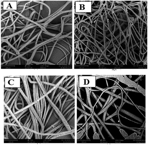
In and , the different morphological structures of the samples with processing parameters are shown. It is evident that changing the solution concentration and spinneret angle significantly affects the structural formation. It is observed that some combinations of solution and process parameters prompt the formation of bio-fibre mat while others cause the formation of fibre network structure. show that spinning at 45° for concentrations of 0.1 g/ml and 0.12 g/ml, would produce a porous mat structure with significant defects. Porous honeycomb-like fibre mats are formed using 0.12 g/ml at 45° and 0.13 g/ml solution concentration at 30° spinner angle. Increase in the concentration to 0.13 g/ml leads to the formation of a highly interconnected network fibre structure. However, further increase in concentration leads to the formation of a mat structure with few defects. These results show that with low solution concentration, bio-mats are formed but with high solution concentration, network fibre structures are produced. The study goal was to form a fine porous 3D structure that can serve as soft tissue for wound dressing applications. This is achieved with a solution concentration of 1.2 g/ml at an angle of 45° (see ). Highly porous 3D structures with large surface to volume ratios are useful in a variety of applications such as antibacterial surfaces (Ji et al., Citation2011), scaffolds (Miao et al., Citation2011), and wound dressing applications. This makes the production of a porous structure a necessity in biomedical engineering. The figure also shows that at low spin angles (30°) micro sized fibres are formed, but at high spin angles (90°), spray sheets are formed. shows that virgin PLA electrospun did not produce honeycomb structure. This is an indication that the presence of particles is instrumental to the formation of a porous structure. Generally, it is observed that the 0.13 g/ml unreinforced PLA fibres spun at 90° () have near uniform diameter without beads and relatively smooth surfaces. The fibres of 0.14 g/ml at 90° () have near uniform diameter with a rough surface, while fibres at 45° of 0.12 g/ml and 30° of 0.12 g/ml have uniform densely knit fibres with near uniform diameters (). In our earlier studies, we reported the formation of natural fibre particle filled micro and nano-sized electrospun fibres suitable for scaffold applications. Bognitzki et al. (Citation2001) reported the presence of pores and dimples on electrospun fibres and proposed phase separation as the main mechanism for the formation of pores and dimples on the fibre surface. Megelski, Stephens, Chase, and Rabolt (Citation2002) also reported that increase in humidity can cause pore formation on the surface of the fibres. However, there has not been any report of the formation of porous mat-like network structure with electrospinning. The structural difference arising from the difference in tilt angle is an indication that despite the use of a needle pump, the tilt angle has a substantial effect on the feed rate of the solution.
Figure 1. Effect of solution concentration on structure formation (a) 0.10 g/ml, 45° and (b) 0.12 g/ml, 45°(c) 0.13 g/ml, 45° (d) 0.14 g/ml, 45°.
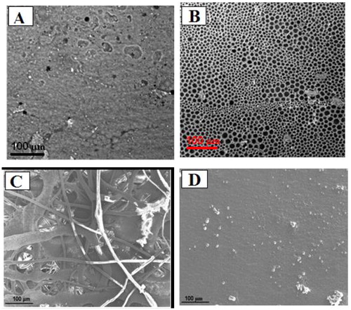
Figure 2. Effect of different parameter combinations (a) 0.11 g/ml, 90° (b) 0.13 g/ml, 30°. N/B: Sample designation represents solution concentration, spinneret angle.
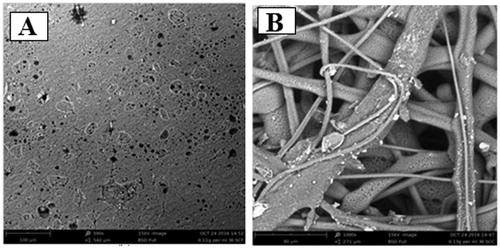
Figure 3. Processed PLA fibres (a) 0.13 g/ml, 90° (b) 0.14 g/ml, 90° (c) 0.12g/ml, 45° (d) 0.12 g/ml, 30°. N/B: Sample designation represents solution concentration, spinneret angle.
3.2. Tensile test
3.2.1 Effects of processing parameters on tensile properties of electrospun fibre
shows the effect of solution concentration on the tensile strength of the spun fibres. It is evident from the figure that tensile strength of the resulting material is strongly dependent on the solution concentration and spinneret angle. This is in line with the report of Gazquez et al. (Citation2017), which identified solution concentration as one of the factors affecting the outcome of electrospinning. For samples processed at 30°spinneret, the tensile strength tends to decrease with increase in solution concentration. However, for 45° and 90° spinneret inclinations, the tensile strength increases initially with increase in concentration to a maximum but decreases with further increase in concentration. This is an indication that there is a threshold concentration where the electrospinning behaviour of the composite changes. This threshold concentration is dependent on the spinneret angle and in this study it occurs at 0.12 g/ml and 0.13 g/ml for 45° and 90° spinneret angles, respectively
Figure 4. Effect of solution concentration on tensile strength of electrospun fibres.
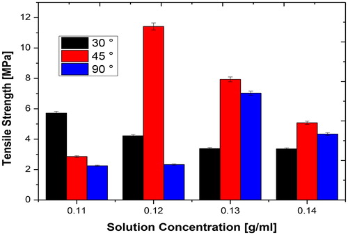
The decrease in tensile strength after the threshold solution concentration was exceeded may be attributed to the increase in diameter of each fibre produced (Amariei, Manea, Bertea, Bertea, & Popa, Citation2017; Butcher, Ching, & Oyen, Citation2017; Siimon, Moisavald, Siimon, & Jarvekulg, Citation2015) and the formation of defects (see ). Thus, higher concentrations enabled the formation of defects prone structure. It has been established that electrospinning solutions with concentrations beyond the threshold will become difficult (Amariei et al., Citation2017; Huan et al., Citation2015) resulting in defective fibre. Tarus, Fadel, Al-Oufy, and El-Messiry, (Citation2016) noted that low concentration helps beads formation, which are detrimental to fibre strength. However, after the threshold concentration the fibres increase in aspect ratio and diameter but with a decrease in strength. The highest tensile strength (11 MPa) is exhibited by the honeycomb structure realised by processing with a solution concentration of 0.12 g/ml at 45° spinneret angle. This relatively high tensile strength compared to others is due to the 3 D honeycomb structure of the fibre produced. Recent results on microcrystalline cellulose electrospun PLA fibres presented by Gaitan and Gacitua, (Citation2018) are lower than those obtained in this study at the same filler weight fraction. Chen and Liu (Citation2008) also obtained lower tensile strength at the same filler weight fraction using cellulose nanocrystals soybean protein fibre. Results obtained from this study are found superior to our earlier report on palm fruit bunch and groundnut shell filled electrospun fibres (Adeosun, Akpan, Gbenebor, Peter, & Olaleye, Citation2016b; Adeosun, Taiwo, et al., Citation2016c). This improved result is attributed to the effect of reinforcement particles on the fibres and the structural stability imparted through synergy between process and material parameters. Thus, composite in this study can serve as soft tissues materials as it is biocompatible and would be preferred to fossil-based composites. Another important note from is the difference in tensile strength with spinneret angle. With a low solution concentration, small tilt angle produces fibres with the best tensile strength. But with high solution concentration and 45° tilt angle, the highest tensile strength fibre is produced. This indicates that small tilt angles favour the feed rate of low solution concentration but when the solution concentration increases, higher tilt angle favours the feed rate.
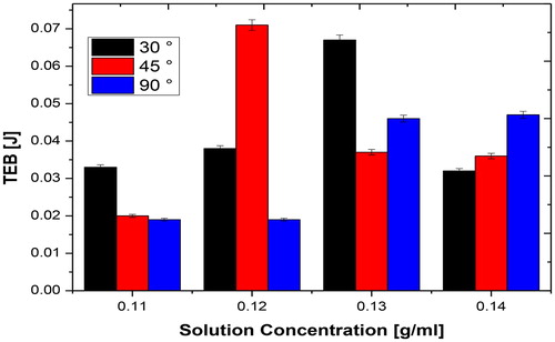
Materials for internal body fixation should withstand long term loading effect without failure and this makes it necessary to examine the fibres’ tensile energy at break (TEB). However, these materials under study are not bulk composites and therefore, the use of conventional testing methods for toughness evaluation cannot be applied. However, tensile energy at break (TEB) is always used as an alternative measurement. TEB is an indication of the total energy absorbed per unit volume of the material up to the point of rupture. It is a measure of the toughness of a material under tensile loading (Adeosun, Akpan, Gbenebor, Peter, & Olaleye, Citation2016b). shows the variation in TEB with an increase in solution concentration and spinneret angle. TEB is found to be strongly dependent on the spinneret angle and solution concentration as it increases with an increase in solution concentration to a maximum before falling with a further increase in solution concentration. For spinneret at 45°, the peak TEB (0.07 J) appears at 0.12 g/ml solution concentration and is consistent with results of tensile strength. This is the highest TEB recorded for all the samples and therefore corroborates the fact that the honeycomb-like structure exhibits greater resistance to rupture. This result is superior to those of groundnut shell and palm fruit bunch filled electrospun fibres reported in our previous studies (Adeosun, Akpan, Gbenebor, Peter, & Olaleye, Citation2016b; Adeosun, Taiwo, et al., Citation2016c). This confirms that electrospinning at 45° inclination produces fibres with higher strength than at 30° and 90°.
Figure 5. Tensile energy of break of electrospun fibres.
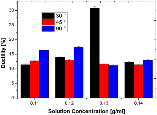
It is observed that the material yield strength coincides with the tensile strength (), and thus, it is important to look at the material strain resistance before yield. shows the influence of solution concentration and spinneret angle on the strain at maximum load. The strain does not show a defined pattern in relation to solution concentration. But, it is noted that nearly all the composites extend for at least 2% before yielding. This is important as some part of the body undergo continuous movement and may exert strain on the material if used as implants. A similar scenario is noted for ductility in where the composite fibres extend by about 10% before fracture. The highest ductility (32%) is exhibited by the sample produced using 0.13 g/ml solution concentration at 30° spin angle. The high fibre ductility and tensile energy at break () is attributed to the highly interconnected fibre network structure ()
Figure 6. Effect of spin angle on the tensile strength of electrospun fibres.
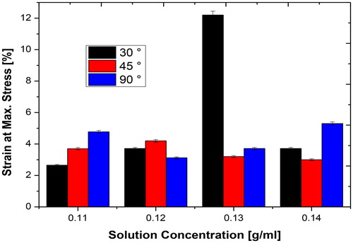
Figure 7. Effect of spin angle on the tensile energy at break of electrospun fibres.
3.2.2. Effect of fibre BCp content on elctrospun PLA
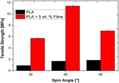
indicates the effect of BCp addition on the tensile strength of the electrospun materials. A very large increase in tensile strength occurred owing to the addition of BCp in all cases. Tensile strength is found to increase by 530, 580 and 280% at 30°, 45° and 90° spinneret angles, respectively. The highest improvement in tensile strength of composite fibre is noted at 45° followed by that obtained at 30°. This improvement in tensile strength is attributed to the presence of bagasse particles in the PLA matrix. As noted earlier, the honeycomb-like structure in 45° formed fibre composite is responsible for the high tensile strength shown by this material. These results are superior to that reported by Liu et al. (Citation2016) for graphene filled electrospun PLA fibre mat, those reported for palm fruit bunch and groundnut shell filled electrospun materials (Adeosun, Akpan, Gbenebor, Peter, & Olaleye, Citation2016a; Adeosun, Akpan, Gbenebor, Peter, & Olaleye, Citation2016b) and compares favourably and even higher than those of PCL and PLA reported by Kancheva, Toncheva, Manolova, and Rashkov, (Citation2015) and Chou and Woodrow (Citation2017). As stated earlier the results obtained in this study are better than those of pure cellulose micro and nano-crystalline filled PLA fibre and fibre mats. This thus indicates treatment of the fibres may not be necessary when there is synergy between electrospinning parameters used.
Figure 8. Effect of fibre addition on tensile strength of electrospun fibres.
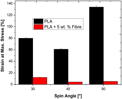
shows that unreinforced PLA fibres possess superior TEB at 45° spin angle. Composite fibre spun at 45° has a porous structure ( and ) while the unreinforced fibre possesses an interconnected network. For other spin angles (30° and 90°), the reinforced PLA fibres possess higher TEB compared to the unreinforced. reveals a large difference between the strain at maximum load for reinforced and unreinforced fibres. In all cases, the virgin PLA fibres possess the highest strain. This is attributed to the presence of homogeneous fibres structure as previous studies have shown that inhomogeneity of fibre matrix owing to particle addition decreases composite ductility (Adeosun, Akpan, Gbenebor, Peter, & Olaleye, Citation2016b).
Figure 9. Effect of fibre addition on tensile energy at break of electrospun fibres.
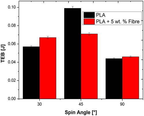
Figure 10. Effect of fibre addition on Strain at maximum load of electrospun fibres.
3.3. Water absorption
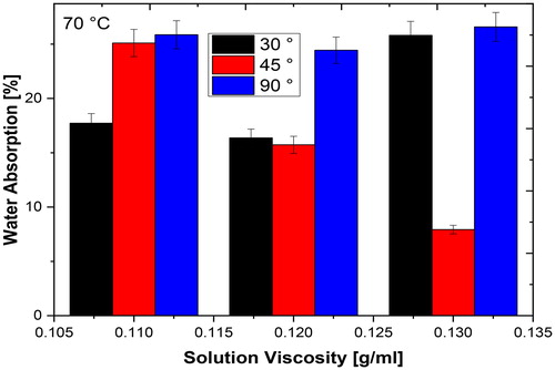
In and the rate of water absorption by the fibres at room temperature and 70°, respectively, are shown. shows the dependency of water absorption capability on solution concentration and spinneret angle. At room temperature, water absorption decreases with increase in solution concentration at all spinneret angles. This indicates that with higher solution concentration the composite fibre forms a more compact structure with reduction in void spaces required for water absorption. On the other hand, samples processed with 45° spinneret angle exhibit the lowest water absorption in all cases. The highest water absorption is shown by the samples spun at 90°. shows a significant effect of elevated temperature on the water absorption behaviour of the fibres. Generally, all the fibre samples show increase in water absorption with increase in temperature. It is important to note that the sample with 0.12 g/ml and 45° has a low capacity for water absorption.
Figure 11. Water absorption of fibres at room temperature.
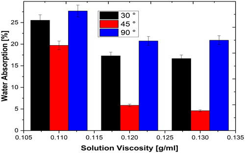
Figure 12. Water absorption behaviour of composites at elevated temperature.
3.4. Thermal properties
The thermo gravimetric (TGA) experiments were run to determine the thermal stability of the formed porous PLA-based fibre mat. shows the difference in thermal degradation of the spun samples with respect to the spinneret angle. The mass loss occurred in two stages: the first one refers to the loss of moisture, solvent, and structural water (25–100 °C) which in this case is negligible; the second is attributed to the thermal degradation of the fibre network structure (300–400 °C). These results are consistent with the findings of Torres-Giner, Gimeno-Alcañiz, Ocio, and Lagaron (Citation2011) and Tammaro et al. (Citation2014). From , fibre samples produced at 45° spinneret angle demonstrate higher onset of degradation and DTG maximum than those at 30 and 90°. On the other hand, it also possesses the lowest residue. The residue may be because of the particles added to the polymer. This superior stability is achieved due to the stability of the structure formed during the electrospinning.
Figure 13. Effect of spinneret angle on thermal degradation.
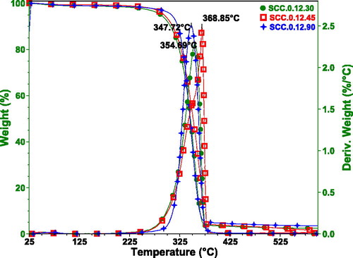
Table 1. Thermal degradation parameters.
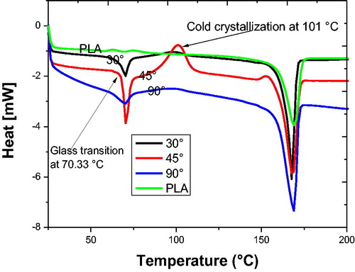
shows the DSC thermogram of the electrospun PLA mat at different spinneret angles. The Tg of the processed samples are the same (70.33 °C) but a lower value is obtained for the unreinforced samples. The Tg of the BCp filled electrospun mat reported here are superior to those reported in literature (Chen, Tsai, & Yang, Citation2011). This may be attributed to the combined effects of the fibres and the network structure produced because of the electrospinning. Cold crystalline peak located at 101 °C is noted for the sample processed at 45°. This does not appear in any other sample. The presence of cold crystallisation has been attributed to freezing of the crystallisation before completion by the removal of solvent from the spun fibre (Chen et al., Citation2011; Inai, Kotaki, & Ramakrishna, Citation2005; Tsuji et al., Citation2006). It is also noted that this material possesses the lowest crystallinity probably due to the presence of the cold crystallisation. Thus, the porous mat produced by electrospinning using 0.12 g/ml solution concentration at 45° spinneret angle possesses a structure different from the others.
Figure 14. Effect of spinneret angle on thermal properties.
4. Conclusion
A porous fibre mat with a honeycomb structure has been fabricated by electrospinning in this study. Results show that the spinneret angles, solution concentration and particle addition have significant effects on the formation of the structure. The use of 45° spinneret angle and 0.12 g/ml solution concentration enabled the formation of the honeycomb structure. Low solution concentration with low spinneret angle enhances the formation of a mat, and network fibre structures are obtained using high solution concentration with high spinneret angle. Neat PLA forms a network of fibres different from particle filled fibres, which indicates that the presence of particles is instrumental to the formation of the mat structure. The sample with the honeycomb structure possesses the highest tensile strength and superior thermal properties coupled with a cold crystalline peak, which is absent in others.
Disclosure statement
No potential conflict of interest was reported by the authors.
Related Research Data
References
- Adeosun, S. O., Akpan, E. I., Gbenebor, O. P., Peter, A. A., & Olaleye, S. A. (2016a). Filler surface nature, bead, solution concentration and fibre diameter of electrospun particle-reinforced polylactide. In TMS 2016: 145th Annual Meeting & Exhibition: Supplemental proceedings (pp. 101–108). New York: John Wiley & Sons, Inc.
- Adeosun, S. O., Akpan, E. I., Gbenebor, O. P., Peter, A. A., & Olaleye, S. A. (2016b). Mechanical behavior of electrospun palmfruit bunch reinforced polylactide composite fibers. JOM: The Journal of the Minerals, Metals & Materials Society, 68(1), 265–270.
- Adeosun, S., Taiwo, O., Akpan, E., Gbenebor, O., Gbagba, S., & Olaleye, S. (2016c). Mechanical characteristics of groundnut shell particle reinforced polylactide nano fibre. Matéria (Rio de Janeiro), 21(2), 482–491.
- Amariei, N., Manea, L. R., Bertea, A. P., Bertea, A., & Popa, A. (2017). The influence of polymer solution on the properties of electrospun 3d nanostructures. IOP Conf. Series: Materials Science and Engineering, 209, 1–7.
- Asran, A., Salama, M., Popescu, C., & Michler, G. H. (2010). Solvent influences the morphology and mechanical properties of electrospun poly(l-lactic acid) scaffold for tissue engineering applications. Macromolecular Symposia, 294(1), 153–161.
- Bognitzki, M., Czado, W., Frese, T., Schaper, A., Hellwig, M., Steinhart, M., … Wendorff, J. H. (2001). Nanostructured fibers via electrospinning. Advanced Materials, 13(1), 70–72.
- Butcher, A. L., Ching, T. K., & Oyen, M. L. (2017). Systematic mechanical evaluation of electrospun gelatin meshes. Journal of the Mechanical Behavior of Biomedical Materials, 69, 412–419.
- Chen, G., & Liu, H. (2008). Electrospun cellulose nanofiber reinforced soybean protein isolate composite Film. Journal of Applied Polymer Science, 110(2), 641–646.
- Chen, H., Tsai, C., & Yang, M. (2011). Mechanical properties and biocompatibility of electrospun polylactide/poly(vinylidene fluoride) mats. J Polym Res, 18(3), 319–327.
- Chou, S., & Woodrow, K. A. (2017). Relationships between mechanical properties and drug release from electrospun fibers of PCL and PLGA blends. Journal of the Mechanical Behavior of Biomedical Materials, 65, 724–733.
- Dotti, F., Varesano, A., Montarsolo, A., Aluigi, A., Tonin, C., & Mazzuchetti, G. (2007). Electrospun porous mats for high efficiency filtration. Journal of Industrial Textiles, 37(2), 151–162.
- Gaitan, A., & Gacitua, W. (2018). Morphological and mechanical characterization of electrospun polylactic acid and microcrystalline cellulose. Bioresources, 13, 3659–3673.
- Gazquez, G. C., Smulders, V., Veldhuis, S. A., Wieringa, P., Moroni, L., Boukamp, B. A., & Elshof, J. E. (2017). Influence of solution properties and process parameters on the formation and morphology of YSZ and NiO ceramic nanofibers by electrospinning. Nanomaterials, 7, 1–15.
- Huan, S., Liu, G., Han, G., Cheng, W., Fu, Z., Wu, Q., & Wang, Q. (2015). Effect of experimental parameters on morphological, mechanical and hydrophobic properties of electrospun polystyrene fibers. Materials, 8(5), 2718–2734.
- Inai, R., Kotaki, M., & Ramakrishna, S. (2005). Structure and properties of electrospun PLLA single nanofibres. Nanotechnology, 16(2), 208–213.
- Ji, W., Sun, Y., Yang, F., Beucken, V., Jeroen, J. J. P., Fan, M., … Jansen, J. A. (2011). Bioactive electrospun scaffolds delivering growth factors and genes for tissue engineering applications. Pharmaceutical Research, 28(6), 1259–1272.
- Kancheva, M., Toncheva, A., Manolova, N., & Rashkov, I. (2015). Enhancing the mechanical properties of electrospun polyester mats by heat treatment. Express Polymer Letters, 9(1), 49–65.
- Kidoaki, S., Kwon, I., & Matsuda, T. (2005). Mesoscopic spatial designs of nano- and microfiber meshes for tissue-engineering matrix and scaffold based on newly devised multilayering and mixing electrospinning techniques. Biomaterials, 26(1), 37–46.
- Liu, W., Li, Z., Zheng, L., Zhang, X., Liu, P., Yang, T., & Han, B. (2016). Electrospun fibrous silk fibroin/poly(L-lactic acid) scaffold for cartilage tissue engineering. Tissue Engineering and Regenerative Medicine, 13(5), 516–526.
- Megelski, S., Stephens, J. S., Chase, D. B., & Rabolt, J. F. (2002). Micro- and nanostructured surface morphology on electrospun polymer fibers. Macromolecules, 35(22), 8456–8466.
- Miao, J., Pangule, R. C., Paskaleva, E. E., Hwang, E. E., Kane, R. S., Linhardt, R. J., & Dordick, J. S. (2011). Lysostaphin-functionalized cellulose fibers with antistaphylococcal activity for wound healing applications. Biomaterials, 32(36), 9557–9567.
- Nam, J., Huang, Y., Agarwal, S., & Lannutti, J. (2007). Improved cellular infiltration in electrospun fiber via engineered porosity. Tissue Engineering, 13(9), 2249–2257.
- Siimon, K., Moisavald, K., Siimon, H., & Jarvekulg, M. (2015). Increasing mechanical strength of electrospun gelatin nanofibers by the addition of aluminum potassium sulfate. Journal of Applied Polymer Science, 132, 42431.
- Tammaro, L., Vittoria, V., Wyrwa, R., Weisser, J., Beer, B., Thein, S., & Schnabelrauch, M. (2014). Fabrication and characterization of electrospun polylactide/β-tricalcium phosphate hybrid meshes for potential applications in hard tissue repair. BioNanoMaterials, 15, 9–20.
- Tarus, B., Fadel, N., Al-Oufy, A., & El-Messiry, M. (2016). Effect of polymer concentration on the morphology and mechanical characteristics of electrospun cellulose acetate and poly (vinyl chloride) nanofiber mats. Alexandria Engineering Journal, 55(3), 2975–2984.
- Teo, W., He, W., & Ramakrishna, S. (2006). Electrospun scaffold tailored for tissue-specific extracellular matrix. Biotechnology Journal, 1(9), 918–929.
- Torres-Giner, S., Gimeno-Alcañiz, J. V., Ocio, M. J., & Lagaron, J. M. (2011). Optimization of electrospun polylactide-based ultrathin fibers for osteoconductive bone scaffolds. Journal of Applied Polymer Science, 122(2), 914–925.
- Tsuji, H., Nakano, M., Hashimoto, M., Takashima, K., Katsura, S., & Mizuno, A. (2006). Electrospinning of poly(lactic acid) stereocomplex nanofibers. Biomacromolecules, 7(12), 3316–3320.
- Wu, J., & Hong, Y. (2016). Enhancing cell infiltration of electrospun fibrous scaffolds in tissue regeneration. Bioactive Materials, 1(1), 56–64.
- Zhu, X., Cui, W., Li, X., & Jin, Y. (2008). Electrospun fibrous mats with high porosity as potential scaffolds for skin tissue engineering. Biomacromolecules, 9(7), 1795–1801.