
 ?Mathematical formulae have been encoded as MathML and are displayed in this HTML version using MathJax in order to improve their display. Uncheck the box to turn MathJax off. This feature requires Javascript. Click on a formula to zoom.
Abstract
Renewable energy schemes have proven to be a viable alternative source of energy generation to off-grid communities. Self-excited induction generators (SEIG) are commonly used as a low-cost energy source; however, their output frequency and voltage must be regulated. This paper therefore proposes a Neural Network (NN)-based power electronics frequency regulation of a SEIG. The NN architecture was designed to manage the solid-state load controller (sLC) to ensure a near-constant load on the SEIG. A reference frequency stability set-point was introduced with the rotor frequency to produce a differential frequency signal which was subsequently trained in the NN using Levenberg-Marquardt model. The surrogate signal from the NN is then compared with a constant saw tooth waveform from the signal generator via a relational operator to generate a pulse width modulation (PWM) signal. The PWM signal controls the firing angle of the insulated gate bipolar transistor (IGBT). Similarly, the duty cycle of the PWM signal from the NN regulates the gate of the IGBT which estimates the magnitude of the dumped power. The set-up was carried out in MATLAB R2018a with a 75 kW, 415 V hydro-driven SEIG under different loading conditions. The feedforward neural network (FFNN) was employed to ensure swift load variation management and frequency control via the power electronic devices. The results from the simulation show that the composite approach of FFNN-sLC was able to manage the load dynamics of the SEIG and subsequently control the load frequency with a fast response time.
1. Introduction
Renewable energy schemes have lately gained prominence when global leaders decided in Glasgow to phase out methane emissions by 2030 (United Nations, Citation2021). This proposal has prompted many researchers to be more interested in researching the full potential of renewable energy initiatives. Although, renewable energy schemes are susceptible to climate change and their output is intermittent (Zhang, Cheng, Mallapragada, Song, & He, Citation2022), however, they are clean and contribute nothing to the greenhouse (Huang, Yang, Yu, Xiong, & Xu, Citation2022). To solve the associated problems with renewable energy schemes such as intermittency, researchers have resorted to harnessing two or more renewable energy sources for the delivery of a sustainable qualitative power supply (Badrudeen, Ariyo, & Nwulu, Citation2024; Jurasz, Canales, Kies, Guezgouz, & Beluco, Citation2020), thereby resolving issues with uncertainties and contingencies (Badrudeen et al., Citation2022a; Badrudeen et al., Citation2022b). This is intended to ensure a robust of output energy amidst their inherent limitations.
As proposed by the World Bank, renewable energy integration for power generation in some selected dispersed communities is of utmost importance to social growth (The World Bank, Citation2017). However, most of these outskirt rural communities are located very far from the national grid, and the cost of extending the transmission lines and support is mostly high with the low economic return of huge capital investment (Fenrick & Getachew, Citation2012). In this situation, a standalone scheme is desirable, especially with the proximity of the potential renewable energy sources to these off-grid communities (Weldcherkos, Salau, & Ashagrie, Citation2021). It is interesting to note that most of these off-grid communities are blessed with several high waterfall sites that can be converted to hydropower stations (Cai, Shi, Guo, & Guo, Citation2021; Marra & Pomilio, Citation1999). These renewable sources are quite promising and sustainable if properly harvested for the generation of electricity for the purpose of micro-electric power.
More interestingly, a self-excited induction generator (SEIG) is fondly used in the renewable energy scheme as a standalone application. The advantages of SEIG lie in its low-cost power generation (Marra & Pomilio, Citation1999), simple pattern of energy conversion (Al-Manfi, Mohamed, & Elsalhin, Citation2022), rigidity to harsh operational conditions (Esquivel-Sancho, Pereira-Arroyo, & Muñoz-Arias, Citation2021), low maintenance (Salau, Nweke, & Ogbuefi, Citation2021), etc. However, SEIG is characterized by unstable output voltage and frequency. In addition, the SEIG output frequency and voltage are greatly affected by the input parameters, for example, consumer load, prime mover speed, and excitation capacitor. Similarly, there is an inverse relation between the consumer load and the terminal voltage (Singh & Murthy, Citation2006). Therefore, in order to maintain a near constant load frequency and voltage when there is a load transition from no-load to full load and vice versa, a potent control mechanism must be put in place such as reactive power control, load control approach, speed control, etc. Meanwhile, a fast response means can be greatly achieved through the artificial neural network (Badrudeen, Nwulu, & Gbadamosi, Citation2023).
This research aims to develop a hybrid control approach of a SEIG using ANN and power electronics as a fast frequency-control mechanism. The study's objectives are to: (1) extract the mathematical model of a SEIG (2) estimate the effect of the loading conditions on the rotor frequency (3) train these variations on an ANN to control the power electronics, and (4) evaluate the execution of the trained data during steady-state and transient conditions. Through this approach, it is expected that the frequency of a standalone SEIG will be immune to variation in the loading variation patterns.
1.1. Review of relevant literature
In the early 90s, Bonert and Hoops (Citation1990) proposed a power electronics-based control technique to ensure the maintenance of regulated frequency and voltage of an IG in a standalone scheme. It is noteworthy to state that special attention was given for the reduction of harmonics introduced to the system from the power electronics controlling components. In the mid-90s, Al-Bahrani and Malik (Citation1993) proposed two techniques for controlling the output voltage of several SEIGs connected in a cascaded arrangement under linear load application. The study considered a different range of similar and dissimilar prime mover speeds. It was reported that the pattern of control is similar for an independently operated SEIG and when several SEIGs are connected. Later in the decade, Suarez and Bortolotto (Citation1999) presented a novel technique for controlling the frequency and voltage of a SEIG. Through the introduction of power electronics devices, reactive power compensation was smoothly achieved. The simulations of different input parameters were explored to determine the responsiveness of the proposed method. The results from the simulation show rigidity of the SEIG to the variations of the input parameters.
In recent times, research is still ongoing in finding the best control method for the voltage and frequency of an IG. Sombir and Singh (Citation2020) presented a control technique for the frequency and voltage of a SEIG with the injection of a photovoltaic system. The authors of the paper introduced a dump load and insulated gate bipolar transistor (IGBT) as control tools to foster frequency and voltage stability. The system is developed in MATLAB and was tested with non-linear and linear loading patterns. Similarly, Chilipi, Sumaiti, and Singh (Citation2020) presented a voltage and frequency-controlled technique for a SEIG in an off-grid scheme. The voltage control was achieved through harmonic compensation from an inverter source. Meanwhile, the variable speed drive was used for the frequency stability control. The system was tested with both single-phase and three-phase loads. The system also introduces a water pumping scheme to act as a buffer to variation in the rotor speed through torque control. The results from the experiment show a stable voltage and frequency at a different type of load. In the paper presented by Sangov, Chorshanbiev, Ismoilov, Balaev, and Vohidov (Citation2020), the potential of an induction generator with an independent windmill to generate electric power for isolated communities was explored. The parameterization of the IG was achieved through the magnetizing curve. The research concluded that capacitors can be used as an effective controlling tool for voltage stability in an IG.
The usefulness of power electronics for the control of the SEIG cannot be overemphasized. This is evident in the paper presented by Esmaeel (Citation2020), where a steady-state evaluation of a windmill-driven SEIG was assessed. The control of voltage was achieved through a combination of bridge diode and inverter-tied thyristor. This arrangement forms a DC correspondence circuit with a calculated firing angle to ensure speed stability at different loading patterns. The study emphasized the influence of the firing angle on SEIG stability. In the same vein, Chermiti and Khedher (Citation2020) proposed a control mechanism for a SEIG in isolated areas. The paper considered a wind power source to supply electric power to water pumping machine load through the IG. The variations in load pattern and the speed of the windmill were controlled to maintain an almost constant output through the static compensator. The setting was implemented in MATLAB/Simulink with a 1.5 kW SEIG. The results were reported to be efficient in controlling the SEIG voltage to a moderate stable state. In addition, Al-Manfi et al. (Citation2022) proposed a technique for controlling a single-phase SEIG by the application of a shunt capacitor. This arrangement was done such that there is a switching mechanism to connect and disconnect the shunt capacitor at a given time interval. This resultant waveform from this practice makes a pulse width modulation. The output parameters of the SEIG such as frequency and voltage were examined under this condition. The thyristor was used to eliminate the differential voltage from the SEIG.
In efforts to solve complex challenges associated with the SEIG, some researchers have expanded their quest to understudy the effect of the SEIG parameterization such as rotor speed, magnetic properties of the stator winding, etc. For instance, Khan, Khan, and Iqbal (Citation2022) investigated the effects of the moment of inertia of the rotor and the stator winding resistance on the performance of the SEIG. This investigation was based on these two performance indices. It was concluded from the results obtained that controlling the rotor speed gives relatively better power stability on SEIG, particularly in a stand-alone scheme. Additionally, Paliwal, Sinha, and Chauhan (Citation2017) presented a unique technique for the evaluation and control of a wind-driven self-excited reluctance generator (SERG) in a stand-alone application. The controlling parameters were frequency and voltage which were achieved through the manipulation of the excitation capacitor. This arrangement was in two ways, first was a short transition of the shunt capacitor and the second was a long switching range of the shunt capacitor. These patterns form a typical pulse width modulation with a varying triggering time. The setup experimented with 1.5 kW SERG. The results from the simulation proved the second arrangement-long switching time- of the connected shunt capacitor provides a better frequency and voltage control. Moreover, Paliwal et al. (Citation2017) considered different classes of induction generators, estimation of the required capacitance value, modes of application, etc. The analysis was centered on voltage and frequency stability assurance.
In addition, Saha and Mahato (Citation2019) evaluated a power quality improvement scheme for a SEIG feeding from a windmill for the generation of power to off-grid areas. The frequency and voltage control through a combined set of static compensators and neuro-fuzzy proportional integral. The load variation on the SEIG seemed to be offset by this approach based on the results obtained from the simulation, thereby, improving the stability of the SEIG in a standalone setting. Similarly, Esquivel-Sancho et al. (Citation2021) introduced a port Hamiltonian control mechanism. The approach is based on the energy conversion model to achieve the stability of the SEIG. This research aims to justify the low-cost maintenance feature of an IG. The results from the study were justified by numerical analysis through simulation. However, Borja, Lescano, Luyo, and Tito (Citation2021) proposed a new method of controlling a three-phase SEIG by estimating its loading limit capacity at a defined speed set before voltage instability. Different load dynamics were considered and the effects on the rotor’s speed were evaluated.
Similarly, Paliwal, Sinha, and Chauhan (Citation2021) highlighted the major setbacks in the SEIG, especially with the application of non-linear load. However, a solution was proposed to this problem through a heuristic method for frequency control. In addition, hybrid methods of genetic algorithm and gravitational search algorithm were employed for selecting the best capacitance value to yield a stable frequency. Meanwhile, Yarlagadda, Karthika, Ambati, and Kumar (Citation2022) proposed a solution to the frequency and voltage instability that is associated with the SEIG. The flexible AC transmission system (FACTS) was employed to regulate the voltage and frequency with the application of linear and non-linear load dynamics. The presented results show that the deployment of FACTS was able to ensure perfect voltage regulation. In the paper presented by Bouyahia, Betin, and Yazidi (Citation2022), a regulating mechanism for a squirrel cage six-phase induction generator that changes state from negative to positive feedback was explored. This is done based on the condition on which the phase plane is operating. The results show that the technique is potent at ensuring the delivery of qualitative power through the deployment of a field-oriented control method.
Another mode of operation of an IG that is commonly used in a standalone setting is a doubly fed induction generator (DFIG). Hossain and Bodson (Citation2022) considered a controlling technique that ensures the speed regulation of a permanent magnet synchronous motor. This approach explored the DFIG as the driven source. Although there was a slight energy conversion loss, the technique was able to control the speed of the permanent magnet synchronous motor at different load perturbations. Similarly, Mondal, Malakar, Tripathy, Krishnaswamy, and Saha (Citation2022) proposed a sliding mode observer method for the speed control of a DFIG working in a standalone scheme. The technique is independent of the variation of the input parameters, especially in mechanical properties (Yesgat, Salau, & Kassahun, Citation2022). The position of the rotor speed was explored to regulate the output voltage of the designed DFIG. However, the Lyapunov criteria were deployed to estimate the sliding gain for the voltage stability. In addition, Zhang and Jiang (Citation2022) presented a performance evaluation analysis of a DFIG based on different controlling techniques. The effect of change in physical quantities such as temperature, humidity, etc. was also considered in the analysis. In the procedural investigation of this research, a high level of affinity was established between the rotor and stator currents, however, to satisfy several control targets for torque and active power, a new rotor reference was used without considering the input parameters of a standalone DFIG. The technique experimented with a 1.5 kW using the hybrid control of rotor current control and field-oriented control. Nonetheless, Gao, Zhao, Gui, Zhou, and Blaabjerg (Citation2021) presented a new technique that combined the Park transformation and feed-forward and feedback structure with no phase lock loop was proposed. This technique ensured the voltage stability of a DFIG in a rigid network and weak network. In the same vein, Hussien, Liu, Xu, Junejo, and Allam (Citation2022) presented a technique that controls the power factor of a brushless DFIG through the field-oriented approach. The stator winding voltage was monitored and controlled by determining the generator’s rotational position. This strategy was validated with the criteria analysis of Popov’s theory. Moreover, Belfedal et al. (Citation2010) addressed the associated problems with the wind-driven DFIG through vector modulation. In addition, the effect of harmonics on the quality of the delivery power was reduced inductively by the filter circuit (Salau, Kanchana, Anoop, Markus, & Braide, Citation2023). The result was compared with the conventional field-oriented method.
1.2. Motivation and contribution of the study to knowledge
The use of machine learning has not been extensively explored for the control of the SEIG in a standalone application as revealed in literature, hence, this study. Similarly, the response period to frequency and voltage regulation under load dynamics were not particularly addressed in the literature. This research paper proposes a smart yet fast hybrid way of regulating the consumer load frequency of a SEIG through a composite approach of ANN and electronic load controller. The proposed supervised control technique is expected to proffer solutions to the challenges of frequency instability due to the variation in consumer load and rotor speed. This research is targeted at ensuring a very fast response time to generator load variations in real time applications. The major contributions of this research include (a) an assessment of load dynamics management on the performance of a standalone SEIG, (b) provision of a valuable insight to frequency control of a SEIG with a composite approach of sLC and ANN as a supervised model, thus, improves the response time to stability substantially and (c) evaluation of the overall performance of a SEIG under steady-state and transient operating conditions.
The remaining part of this paper is arranged as follows. Section 2 presents the proposed methodology. The proposed system is described in the same section. Section 3 presents the results and discussion, while the conclusion is presented in Section 4.
2. Materials and methods
In this section, the control of the load frequency of a standalone SEIG using ANN algorithm and solid state load controller was investigated. The controller’s performance was evaluated under steady-state and transient operating conditions.
2.1. Mathematical modeling of SEIG
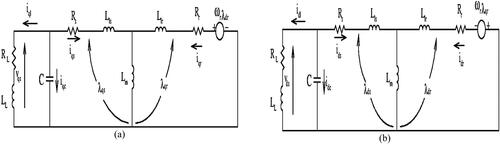
In this research, the effect of the following parameters was neglected in the modeling of the three-phase SEIG; namely: (a) change in temperature and (b) core loss. The depiction of the SEIG in the d-q axis is shown in . The modeling of the SEIG is described by Equation (1) (Badrudeen, Ayinde, Ariyo, & Ogunnigbo, Citation2021). The reduced typical circuit model in d-q reference frame is shown in .
Figure 1. SEIG in d–q axis.
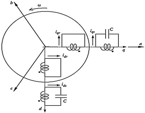
Figure 2. Typical SEIG in the d-q stationary reference frame (a) q axis (b) d axis.
where column vectors x and y are represented as and
However,
A and B matrices are described as follows
where k is defined by EquationEquation (2)
(2)
(2)
(2)
(2)
is the SEIG rotor speed, and the current components of stator, rotor, and load currents are
respectively while,
are stator, rotor and load voltages, respectively. However,
are stator and rotor resistance, respectively, and
and
are stator self-inductance, rotor self-inductance and mutual inductance between stator and rotor, respectively.
2.2. Parameterization of the modeled SEIG
The magnetizing current, im of the SEIG in the d-q axis from is given in Equation (3). The nonlinear properties of the SEIG operating close to the saturation state are considered.
(3)
(3)
The resulting torque, Te from the electromagnetic induction is expressed in Equation (4).
(4)
(4)
where P is the number of poles.
2.3. Modeling of hydropower system
Hydroelectric power is a renewable energy technology that harnesses the energy of flowing water to produce electrical energy. Of course, it is regarded as one of the oldest and most widely used forms of clean energy generation. Aside that, the water flow with minimal head is almost available in all remote communities. The generating capacity of hydropower plants are used to classify them viz. mini, micro, small, medium and large-scale hydropower system. The mathematical modeling of a typical hydropower system is given in EquationEquations (5)(5)
(5) and Equation(6)
(6)
(6) (He et al., Citation2023).
(5)
(5)
(6)
(6)
where
defines the power from the hydropower plant at time, t,
is the flow rate at time t,
describes the area of the hydropower plant’s rotor.
and
are power coefficient and hydro to electricity conversion efficiencies of the hydropower plant, respectively.
and
are water density and water velocity at time, t, respectively.
2.3.1. Micro hydropower
Micro hydropower refers to a small-scale hydroelectric power generation system that harnesses the energy of flowing water to produce electricity. Typically, micro hydropower installations have a capacity of less than 100 kilowatts, making them ideal for remote or off-grid locations. This sustainable and renewable energy source can be a valuable solution for providing clean and reliable power in areas with access to flowing water resources, offering environmental benefits and energy independence. The modeling expression of a typical micro hydropower plant is given in EquationEquation (7)(7)
(7) (Hermann et al. Citation2022).
(7)
(7)
where
describes the water density,
is the gravitational acceleration,
is the micropower plant head,
represents the water flow rate and
represents the hydro to electricity conversion efficiency of the turbine.
2.4. The proposed control scheme of a SEIG
The schematic representation of the proposed frequency control technique is shown in (Badrudeen et al., Citation2021). The setup consists of a frequency regulation unit, a load management unit, a voltage regulation unit, and the prime mover. A small hydro-driven source is considered with a 75 kW three-phase SEIG.
Figure 3. Schematic diagram of the proposed hybrid control technique of a Hydro-driven SEIG.
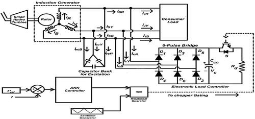
The proposed ANN hybrid frequency control system is designed to ensure a constant load frequency at different consumer’s loading patterns. The set-up consists of a SEIG with the specifications of 75 kW, 415 V, 4.8 A, excitation capacitor, consumer load, dump load, ANN control unit, and power electronics devices. The tachogenerator was deployed to quantify the rotor speed of the SEIG and subsequently converted to frequency through the voltage to frequency converter to produce a rotor frequency, f. The IGBT is controlled by the ANN controller by comparing the reference frequency f*ref to the rotor frequency, f as shown in . The waveform from the output layer of the ANN is then compared with the fixed sawtooth to generate a varying duty cycle signal to control the firing angle of the IGBT. A suitable capacitance value of the capacitor is connected across the secondary winding of the SEIG for the reactive power compensation and voltage stability regulation. The bridge rectifier converts the AC to DC voltage for seamless control by the power electronics components. The ripple from the resultant pulsating signal is filtered by the shunt capacitor. The proposed technique employed the insulated gate bipolar transistor (IGBT) as a chopper switch to supply a variable DC voltage across the dump load (Rd). The arrangement is to satisfy EquationEquation (5)(5)
(5) , such that the SEIG power (PSEIG) comprises of the consumer power load (PConsumer) and the dumb power load (PDump).
(8)
(8)
2.5. Parameterization of solid state load controller circuit
The parameters of the solid-state load controller (sLC) comprise an unregulated six-pulse diode rectifier, a parallel resistive load (dump load), a shunt capacitor, IGBT, and an ANN control unit. The gate of the IGBT is driven by the prompt command signal from the ANN algorithm. The percentage of the dissipated power is determined by the duty cycle of the IGBT via the gate firing angle. The DC output voltage of the uncontrolled bridge rectifier is given in EquationEquation (9)(9)
(9) .
(9)
(9)
where
is the SEIG line-to-line voltage. Moreover, the resistance value, Rd of the dumbed load is expressed in EquationEquation (10)
(10)
(10) .
(10)
(10)
In addition, the value of the capacitance, C, of the shunt capacitor is described in EquationEquation (11)(11)
(11) based on the ripple factor, r, and the pulsating frequency,
(11)
(11)
2.6. ANN controller for DC bus chopper
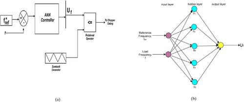
This research considers a hydro-driven SEIG as shown in . The set-up possesses two (neurons) input parameters which are the rotor frequency and the reference frequency. The speed-to-frequency converter was employed to estimate the rotor frequency from the tacho-generator. Different loading conditions of the SEIG were used to generate the training data to the ANN. The hidden layer comprises of five Equation(5)(5)
(5) neurons while the output layer has just one (1) neuron, Uf. The Uf from the ANN system is then compared with a constant sawtooth waveform from the signal generator to generate a pulse width modulation (PWM) waveform signal. The PWM signal from the relational operator is used to control the duty cycle of the IGBT. This arrangement enables the IGBT to estimate the percentage of power to dissipate in Rd until the frequency stability is attained. In other words, the proposed ANN controlling scheme is invariably controlling the ELC of a SEIG for frequency stability.
Figure 4. ANN frequency control unit (a) block diagram (b) constructed FFNN architecture.
2.7. Selection of the ANN structure
In this research, the feedforward neural network (FFNN) architecture was employed using Levenberg-Marquardt training model. The input data are the reference frequency and the rotor frequency. The hidden layer has log sigmoid of five Equation(5)(5)
(5) neurons and an output layer of one (1) neuron, Uf as shown in . The trained frequency, Uf, is the resultant signal from the ANN output layer. The choice of the 2
5
1 ANN pattern was based on the empirical factor for an enhanced learning capability and to avoid under-fitting since the input variables considered in this research are few in number.
3.7. Testing the network
The data from the rotor frequency of the considered induction generator operating under different loading conditions were set as the training and target data. The training data and target data are seventy percent and thirty percent, respectively. The Levenberg–Marquardt model was deployed for the training and the performance index of the network was the mean squared error.
4. Results and discussion
The assessment of the proposed SEIG frequency-controlled system operating under steady-state conditions and transient conditions was evaluated in this section.
4.1. Assessment of the proposed ANN controller
The assessment of the proposed technique was determined through the examination of the trained system to maintain an acceptable frequency stability range at different loading conditions. Similarly, the performance assessment was based on the behavior of the induction generator and the response time of the power electronics circuit to load variations before the frequency stability is attained. The best validation performance of the system is at epoch 3. This implies that the system response time to frequency stability is very short and perhaps, the convergence time of the rotor frequency to match with the reference frequency is almost imminent. The degree of deviation of the rotor frequency from the reference frequency is measured as the mean squared error is 0.39265. A ten-test point from different data set-points of load power and percentage dumb load, rotor frequency before and after ANN control is presented in . The performance of the proposed technique to frequency stability at different loading conditions is shown in .
Figure 5. Load dynamics management under NN controlled frequency regulation (a) response time (b) test points (c) switching time from rotor frequency to controlled load frequency.
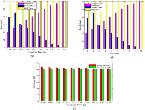
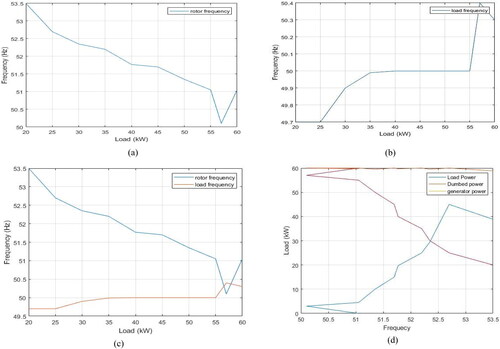
Figure 6. Frequency responses at varying consumer load (a) rotor frequency before control (b) controlled load frequency (c) switching points between the rotor and controlled load frequency (d) rotor frequency under ANN load management.
4.2. Assessment of the SEIG load frequency using ANN controller under transient condition
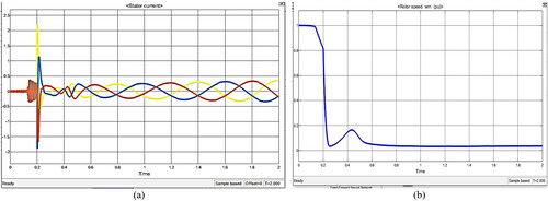
The performance of the SEIG was assessed under transient conditions by applying a sudden load of 50 kW at about 0.2 s under open circuit breaker condition. The waveform from the loading pattern shows a voltage drop and this resulted in a spike in stator current as shown in . The rotor speed moved from an unstable state to a stable state at almost 0.45 s after the activation of the IGBT as depicted in .
Figure 7. SEIG parameters under transient condition (a) stator current (b) rotor speed dynamics.
4.3. Assessment of the SEIG load frequency using ANN controller under steady-state condition
The consumer load connected to the SEIG was linearly decreased to assess the actions of the ANN frequency-controlled system during the steady-state loading condition. It was observed from the result the SEIG was able to maintain a stable frequency 50 ± 1%Hz and voltage as depicted in . The dump power increases with the response to the decrease in the consumer load power such that the total operating SEIG power to give frequency stability is ensured as the load varies with time. This pattern supports the established expression in EquationEquation (8)(8)
(8) as presented in .
Figure 8. Voltage regulations at different loading conditions (a) controlled load frequency (b) test points.
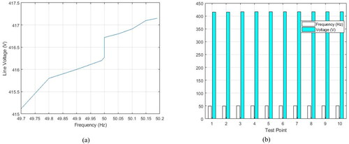
Table 1. Rotor frequency and load frequency using FFNN-sLC controller.
4.4 Comparative analysis of state-of-the-art SEIG control techniques
The proposed hybrid approach was able to control the rotor frequency to a reference frequency through the composite actions of the FFNN and sLC. The average recovery time to load variation is at 1.02s. Most literatures did not emphatically discuss the recovery time before frequency stability. The long switching time to frequency stability recovery is not suitable for smooth operation of the SEIG (Sedky, Yassin, Hanafy, & Ismail, Citation2021). Paliwal et al. (Citation2021) and Zhang and Jiang (Citation2022) investigated a combination of two controlling methods for frequency and voltage stability, however, none of this research discusses the recovery time. Similarly, research by Saha and Mahato (Citation2019) and Paliwal et al. (Citation2021) employed machine learning techniques; meanwhile, the average response time to load dynamics is relatively higher. The results presented by Weldcherkos et al.,(Citation2021), Singh and Murthy (Citation2006), Khan et al. (Citation2022), Sedky et al. (Citation2021), and Mondal et al. (Citation2022) are convincing, however, the proposed FFNN-sLC is relatively better in terms of the response time to frequency stability as a result of load dynamics.
5. Conclusion
This paper presented a supervised fast-response frequency control scheme for an isolated SEIG using ANN and sLC. The scheme was developed and implemented in MATLAB/Simulink with an induction generator of 75 kW, 415 V. The electronic load controller was employed to manage the load variation of the SEIG through the prompt command signal of the ANN algorithm. The gate of the IGBT was controlled by the generated pulse width modulation waveform from the relational operator after being trained with the ANN. The generated PWM waveform determines the duty cycle of the dissipated power to the dumb load through the IGBT. This technique was validated through the performance assessment of the proposed technique for the purpose of maintaining a constant load frequency under steady-state conditions and transient-state conditions. In addition, different loading patterns were also used to establish the potency of the hybrid FFNN-sLC controlled technique for a stable frequency assurance of the isolated SEIG. The results obtained from the steady-state and transient-state analysis on the 75 kW SEIG in MATLAB/Simulink show that the ANN-sLC was able to control the load frequency to about 50 Hz 1% with a fast switching and response time to frequency stability for different loading conditions when compared with conventional electronic load controllers.
Data availability statement
The datasets generated during and/or analysed during the current study are not publicly available but are available from the corresponding author on reasonable request.
Disclosure statement
No potential conflict of interest was reported by the author(s).
Additional information
Funding
References
- Al-Bahrani, A. H., & Malik, N. H. (1993). Voltage control of parallel operated self excited induction generators. IEEE Transactions on Energy Conversion, 8(2), 236–242. doi:10.1109/60.222710
- Al-Manfi, A., Mohamed, W. A., & Elsalhin, E. F. (2022) Voltage control of stand-alone single phase self excited induction generator for variable speed wind turbine using Bang Bang-PWM controller. 2022 IEEE 2nd International Maghreb Meeting of the Conference on Sciences and Techniques of Automatic Control and Computer Engineering (MI-STA). pp. 749–754, doi:10.1109/MI-STA54861.2022.9837503
- Badrudeen, T. U., Ariyo, F. K., & Nwulu, N. (2024). Voltage stability improvement and power losses reduction through multiple grid contingency supports. Energy Exploration & Exploitation, 42(4). doi: 10.1177/01445987231218292
- Badrudeen, T. U., Ariyo, F. K., Gbadamosi, S. L., & Nwulu, N. I. (2022b). A novel classification of the 330 kV Nigerian power network using a new voltage stability pointer. Energies, 15(19), 7247. (2022b) doi:10.3390/en15197247
- Badrudeen, T. U., Ariyo, F. K., Salau, A. O., & Braide, S. L. (2022a). Analysis of a new voltage stability pointer for line contingency ranking in a power network. Bulletin of Electrical Engineering and Informatics, 11(6), 3033–3041. doi:10.11591/eei.v11i6.4266
- Badrudeen, T. U., Ayinde, T. O., Ariyo, F. K., & Ogunnigbo, C. O. (2021). Performance evaluation of a frequency controlled three phase self-excited induction generator using artificial neural network. 2nd International Conference on Engineering and Environmental Sciences (pp. 39–47).
- Badrudeen, T. U., Nwulu, N. I., & Gbadamosi, S. L. (2023). Neural network based approach for steady-state stability assessment of power systems. Sustainability, 15(2), 1667. doi:10.3390/su15021667
- Belfedal, C., Gherbi, S., Sedraoui, M., Moreau, S., Champenois, G., Allaoui, T., & Denaï, M. A. (2010). Robust control of doubly fed induction generator for stand-alone applications. Electric Power Systems Research, 80(2), 230–239. doi:10.1016/j.epsr.2009.09.002
- Bonert, R., & Hoops, G. (1990). Stand alone induction generator with terminal impedance controller and no turbine controls. IEEE Transactions on Energy Conversion, 5(1), 28–31. doi:10.1109/60.50808
- Borja, M., Lescano, S., Luyo, J. E., & Tito, U. Y. (2021). MPPT of three-phase self-excited induction generator during electric power generation from variable power sources. 2021 1st International Conference on Power Electronics and Energy (ICPEE) (pp. 1–6), doi:10.1109/ICPEE50452.2021.9358538
- Bouyahia, O., Betin, F., & Yazidi, A. (2022). Optimal sliding mode control of a symmetrical six-phase induction generator for wind turbines. IEEE Transactions on Industry Applications, 58(6), 7308–7317. doi:10.1109/TIA.2022.3195971
- Cai, J., Shi, J., Guo, J., & Guo, K. (2021). Sizing optimization of wind-hydro combination system based on frequency division. 2021 3rd Asia Energy and Electrical Engineering Symposium (pp. 391–395). doi:10.1109/AEEES51875.2021.9403051
- Chermiti, D., & Khedher, A. (2020). A wind-water pump driven by a self excited induction generator installed in stand-alone. 2020 17th International Multi-Conference on Systems, Signals & Devices (SSD) (pp. 824–829), doi:10.1109/SSD49366.2020.9364215
- Chilipi, R., Sumaiti, A. A., & Singh, B. (2020) Control of self-excited induction generator-based micro-hydro power generation system feeding single-phase and three-phase loads. 2020 IEEE Industry Applications Society Annual Meeting (pp. 1–8). doi:10.1109/IAS44978.2020.9334806
- Esmaeel, M. (2020). Steady state analysis of a wind energy driven self excited induction generator (SEIG). 2020 8th International Conference on Smart Grid (icSmartGrid) (pp. 101–108). doi:10.1109/icSmartGrid49881.2020.9144953
- Esquivel-Sancho, L., Pereira-Arroyo, R., & Muñoz-Arias, M. (2021). Voltage regulation for a self-excited induction generator. 2021 60th IEEE Conference on Decision and Control (CDC) (pp. 1336–1341), doi:10.1109/CDC45484.2021.9682864
- Fenrick, S. A., & Getachew, L. (2012). Cost and reliability comparisons of underground and overhead power lines. Utilities Policy, 20(1), 31–37. 2012doi:10.1016/j.jup.2011.10.002
- Gao, S., Zhao, H., Gui, Y., Zhou, D., & Blaabjerg, F. (2021). An improved direct power control for doubly fed induction generator. IEEE Transactions on Power Electronics, 36(4), 4672–4685. doi:10.1109/TPEL.2020.3024620
- He, Y., Guo, S., Dong, P., Zhang, Y., Huang, J., & Zhou, J. (2023). A state-of-the-art review and bibliometric analysis on the sizing optimization of off-grid hybrid renewable energy systems. Renewable and Sustainable Energy Reviews, 183, 113476. doi:10.1016/j.rser.2023.113476
- Hermann, D. T., Donatien, N., Konchou Franck Armel, T., & René, T. (2022). Techno-economic and environmental feasibility study with demand-side management of photovoltaic/wind/hydroelectricity/battery/diesel: A case study in Sub-Saharan Africa. Energy Conversion and Management, 258, 115494. doi:10.1016/j.enconman.2022.115494
- Hossain, M. A., & Bodson, M. (2022). Control of a PMSM using the rotor-side converter of a doubly fed induction generator for hybrid-electric propulsion. IEEE Transactions on Control Systems Technology, 30(4), 1758–1765. doi:10.1109/TCST.2021.3113885
- Huang, J., Yang, Z., Yu, J., Xiong, L., & Xu, Y. (2022). Frequency dynamics-contrained parameter design for fast frequency controller of wind turbine. IEEE Transactions on Sustainable Energy, 13(1), 31–43. Jan2022 doi:10.1109/TSTE.2021.3102611
- Hussien, M. G., Liu, Y., Xu, W., Junejo, A. K., & Allam, S. M. (2022). Improved MRAS rotor position observer based on control winding power factor for stand-alone brushless doubly-fed induction generators. IEEE Transactions on Energy Conversion, 37(1), 707–717. doi:10.1109/TEC.2021.3110776
- Jurasz, J., Canales, F. A., Kies, A., Guezgouz, M., & Beluco, A. (2020). A review on the complimentary of renewable energy sources: Concept, metric, application and future research directions. Solar Energy, 195(11), 703–724. doi:10.1016/j.solener.2019.11.087
- Khan, M. F., Khan, M. R., & Iqbal, A. (2022). Effects of induction machine parameters on its performance as a standalone self excited induction generator. Energy Reports, 8, 2302–2313. doi:10.1016/j.egyr.2022.01.023
- Marra, E. G., & Pomilio, J. A. (1999). Self-excited induction generator controlled by a VS-PWM bidirectional converter for rural applications. IEEE Transactions on Industry Applications, 35(4), 877–883. doi:10.1109/28.777197
- Mondal, P., Malakar, M., Tripathy, P., Krishnaswamy, S., & Saha, U. (2022). Robust observer design for sensorless voltage and frequency control of a doubly fed induction generator in standalone mode. IEEE Transactions on Energy Conversion, 37(2), 844–854. doi:10.1109/TEC.2021.3126779
- Paliwal, S., Sinha, S. K., & Chauhan, Y. K. (2017). Performance optimization of self excited induction generator: A state of art. 2017 Recent Developments in Control, Automation & Power Engineering (RDCAPE) (pp. 416–420). doi:10.1109/RDCAPE.2017.8358307
- Paliwal, S., Sinha, S. K., & Chauhan, Y. K. (2021). Frequency control of 5 kW self-excited induction generator using gravitational search algorithm and genetic algorithm. In AI and IOT in renewable energy. Singapore: Springer. doi:10.1007/978-981-1101-0_8
- Saha, B., & Mahato, S. N. (2019). Power quality improvement of a self-excited induction generator using NFPI controller based hybrid STATCOM system. 2019 IEEE International Conference on Intelligent Techniques in Control, Optimization and Signal Processing (INCOS) (pp. 1–4), doi:10.1109/INCOS45849.2019.8951424
- Salau, A. O., Kanchana, K., Anoop, K. J., Markus, E. D., & Braide, S. L. (2024). Suppression of over voltage in SiC-based inverter fed induction motor. Australian Journal of Electrical and Electronics Engineering, 21(1), 11–28. doi:10.1080/1448837X.2023.2250132
- Salau, A. O., Nweke, J. N., & Ogbuefi, U. C. (2021). Effective implementation of mitigation measures against voltage collapse in distribution power systems. Przeglad Elektrotechniczny, 97, 65–68. doi:10.15199/48.2021.10.13
- Sangov, K., Chorshanbiev, S. R., Ismoilov, F. O., Balaev, M. A., & Vohidov, M. M. (2020). Three-phase self-excited induction generator for windmills analytical techniques and experimental results. 2020 International Youth Conference on Radio Electronics, Electrical and Power Engineering (REEPE) (pp. 1–6). doi:10.1109/REEPE49198.2020.9059122
- Sedky, J., Yassin, H. M., Hanafy, H. H., & Ismail, F. (2021). Voltage and frequency control of standalone wind-driven self-excited reluctance generator using switching capacitors. Journal of Electrical Systems and Information Technology, 8(6), 23. doi:10.1186/s43067-021-00030-1.
- Singh, B., & Murthy, S. S. (2006). A steady state analysis on voltage and frequency control of self-excited induction generator in micro-hydro system. 2006 International Conference on Power Electronic, Drives and Energy Systems (pp. 1–6). doi:10.1109/PEDES.2006.344278
- Sombir, S., & Singh, M. (2020). Voltage and frequency control of self excited induction generator integrated with PV system. IECON 2020 The 46th Annual Conference of the IEEE Industrial Electronics Society (pp. 4306–4311), doi:10.1109/IECON43393.2020.9254608
- Suarez, E., & Bortolotto, G. (1999). Voltage-frequency control of a self-excited induction generator. IEEE Transactions on Energy Conversion, 14(3), 394–401. doi:10.1109/60.790888
- The World Bank. (2017). The rural electrification project stage II.
- United Nations. (2021). COP26: The Glasgow climate pact. UN Change Conference, Nov. 2021. UK in partnership with Italy.
- Weldcherkos, T., Salau, A. O., & Ashagrie, A. (2021). Modeling and design of an automatic generation control for hydropower plants using neuro-fuzzy controller. Energy Reports, 7, 6626–6637. doi:10.1016/j.egyr.2021.09.143
- Yarlagadda, V., Karthika, G. A., Ambati, G., & Kumar, C. S. (2022). Wind energy system using self excited induction generator with hybrid facts device for load voltage control. International Conference on Electrical and Electronics Engineering, 1, 77–91.
- Yesgat, A. W., Salau, A. O., & Kassahun, H. E. (2022). Fuzzy based sliding mode control of vector controlled multiphase induction motor drive under load fluctuation. Journal of Electrical and Electronics Engineering, 15(2), 98–105.
- Zhang, Y., & Jiang, T. (2022). Robust predictive rotor current control of a doubly fed induction generator under an unbalanced and distorted grid. IEEE Transactions on Energy Conversion, 37(1), 433–442. doi:10.1109/TEC.2021.3104410
- Zhang, Y., Cheng, V., Mallapragada, D. S., Song, J., & He, G. (2022). A model adaptive clustering based time aggregation method for low-carbon energy system optimization. IEEE Transactions on Sustainable Energy, 14(1), 55–64. doi:10.1109/TSTE.2022.3199571