
Abstract
Additive manufacturing (AM) by laser powder bed fusion (LPBF) involves melting of layers of powder onto a substrate, called a building platform. Due to cost or convenience considerations, building platform materials rarely match the LPBF material, especially for high temperature materials. To ensure tolerances in component geometries, AM components are often stress-relieved/heat-treated while still attached to the building platform. It is therefore important to understand the effect of dissimilar building platform materials on the properties of the built-up material. These effects may be particularly important for high performance materials such as Ni-base superalloys used for critical applications in the aerospace and energy industries. To investigate this effect, samples of a Ni-base superalloy HAYNES® 282® were built onto a carbon steel building platform in several configurations. The samples were removed from the building platform after heat treatment and subjected to detailed composition analysis and microstructural characterization to investigate the effect of the building platform material on the properties of the additively manufactured part. Room temperature and high temperature tensile testing were used to characterize the material. Results showed no risk of large-scale chemical composition change, or mechanical property degradation of built-up material from on-platform heat treatment.
Introduction
Increasing maturity of additive manufacturing (AM) in general and laser powder bed fusion (LPBF) in particular has resulted in a major disruption in manufacturing. The technology allows for greater freedom of design, meaning geometries and functionalities can be realized that would not be possible to create with conventional manufacturing processes. Parts can be produced very close to net shape with little or no machining required, meaning material waste is greatly reduced. This characteristic is particularly valuable for high-temperature and high-performance alloys for which the raw material is expensive. Ni-base superalloys are an example of such materials and are widely used in critical industries such as aerospace or energy. However, Ni-base superalloys have complex compositions and careful control of the manufacturing process chain is required to ensure robust and reliable material performance.
LPBF has shown the ability to produce parts with very low porosity and excellent mechanical properties, and is increasingly being used for making parts in demanding applications in several industries. In the LPBF process, a high-powered laser is used to melt and consolidate metal powder onto a building platform to form the profile of a desired part. The building platform is then lowered by the height of a layer of powder, additional powder is spread onto the now solidified layer, and the process repeats until a three-dimensional part is created within a powder bed. To achieve complete fusion between layers, melt depth exceeds the powder layer thickness.
The initial stages of a typical LPBF process chain are schematically represented in . The first step is the actual LPBF process, or printing of the part that is built onto a building platform. Through repeated melting, solidification, and thermal cycling, the LPBF process introduces residual stresses into the printed part. Depending on material and the printed geometry, the part may distort if separated from the building platform without relieving these residual stresses. The required stress relief is achieved by heat treatment, which may be either a dedicated stress relief heat treatment or a heat treatment primarily intended for another purpose. Following this step, the part is separated from the building platform by means of wire electric discharge machining (EDM) or a bandsaw.
Figure 1. Typical manufacturing process flow of an additively manufactured part in a production environment.
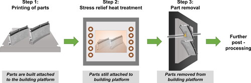
Materials used for building platforms should ideally be similar to the materials being printed, so that strong bonding between part and building platform can be achieved. However, it can be impractical to use Ni-alloys as building platform materials, and carbon steel is often used instead. Use of Ni-alloys is limited because of several factors. Ni-alloys are several times more expensive than steel—in the commodity market the cost of Ni is typically ≈20 times that of steel. Ni-alloys (depending on the specific alloy) tend to age harden and become difficult to machine, whereas carbon steels are less likely to react to the typical stress relieving heat treatment cycle, and remain machinable and easy to re-surface and re-use. Steels are also much more widely available. Nevertheless, use of this carbon steel/Ni-alloy dissimilar material couple during stress relief heat treatment raises the question of contamination by unwanted alloying elements.
Composition limits for high performance materials such as Ni-base superalloys are tightly controlled, particularly in the aerospace industry. It is well known that small amounts of tramp elements can seriously degrade the high temperature performance of Ni-base alloys (Geddes, Leon, & Huang, Citation2010; Osgerby & Gibbons, Citation1992; Sims, Stoloff, & Hagel, Citation1987). The potential diffusion of harmful elements from a carbon steel building platform into the Ni-alloy could lead to non-conformance with material standards, as well as poor material performance. Depletion of important alloying elements, such as oxide formers or grain boundary strengtheners, could have similarly negative effects. These effects could possibly be mitigated by building parts on supports, rather than with direct connection to the platform.
Currently, there is no published research that examines the effect of heat treatment on the interface between a Ni-alloy and a steel building platform. Therefore, this study aims to understand the effect of building and heat treating an iron-free Ni-base superalloy Haynes® 282® on a carbon steel building platform.
Materials and methods
Test samples were manufactured in an EOS M290 LPBF system (Electro Optical Systems GmbH, Krailling, Germany) which has a building volume of 250 mm × 250 mm × 325 mm. The building platform material was carbon steel with its nominal composition corresponding to EN C45U (1.1730) (DIN EN ISO 683-1, Citation2018). The powder used for the LPBF process was gas atomized Haynes® 282® powder with a particle size distribution between 15 µm and 45 µm. Composition of the powder, along with the nominal compositional limits of Haynes® 282® according to SAE AMS 5951A (Haynes International Inc., • • • •; SAE International, Citation2010–12) is given in . Printing was performed using 40 µm layer thickness with the “HAYNES282_040_080_CoreM291_111” process parameter set from EOS under argon atmosphere. A scanning strategy using 10 mm wide stripes and rotation of 47° between layers was used, and the “Strong Platform Connection” feature was enabled for the build.
Table 1. Nominal and actual chemical compositions of Haynes® 282® superalloy powder (from powder manufacturer) and steel building platform (measured).
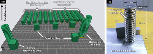
Several sample geometries were manufactured, as seen in , including samples built with direct connection to the platform and samples built on supports. Cuboids of 15 mm × 15 mm × 18 mm height were printed for analysis of the microstructure and interface with the building platform. Tall samples referred to as “stacked discs” were also printed for analysis of the chemical composition at different build heights. Each disc in these samples was 3 mm in height. Horizontally oriented tensile test blanks with hexagonal cross section and length of 80 mm were also printed for mechanical testing.
Figure 2. (a) Layout of various test samples on building platform in the test print; (b) stacked disc sample on steel building platform.
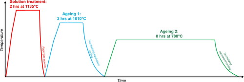
One cuboid and stacked disc sample each were removed from the building platform after printing (prior to heat treatment) for analysis in the as-built condition. A bandsaw was used to remove these samples with several millimeters of building platform material attached to the LPBF built material. The remaining building platform was heat treated in a TAV H4-S type industrial vacuum furnace (TAV Vacuum Furnaces SPA, Caravaggio BG, Italy) according to the heat treatment scheme given in . This is the standard solution and ageing heat treatment recommended for the wrought Haynes® 282® material by Haynes Intl and required by SAE AMS 5951A. Pressurized argon gas was used for the cooling steps in the vacuum furnace. After heat treatment, the remaining samples were removed from the building platform using wire EDM.
Figure 3. Schematic representation of heat treatment applied to the building platform and printed parts.
Samples for metallography and microstructure analysis were prepared by mounting in Struers Polyfast conductive resin and grinding progressively with SiC papers up to P1000 paper. This was followed by polishing to 1 µm with diamond suspensions and polishing cloths and further polishing with 0.25 µm fumed silica suspension until grain boundaries were just visible. The steel portion of the metallographic samples was swab etched using a 2% Nital solution. Nital was found to have no effect on the Haynes® 282® parts of the sample.
The stacked disc samples were cut in the horizontal plane using a precision cutting abrasive saw for chemical analysis. Metallic alloying elements as well as Si were measured by induction-coupled plasma optical emission spectroscopy (ICP-OES) on a Spectro Arcos (Spectro Analytical Instruments GmbH, Germany). Carbon and sulfur were analyzed by infrared absorption after combustion in an induction furnace on a LECO CS844 (LECO Corporation, USA). Oxygen and nitrogen were analyzed by inert gas fusion on a LECO ON836 elemental analyzer.
An Olympus GX51 optical microscope was used for low magnification imaging of the metallographic samples. A Zeiss GeminiSEM 450 scanning electron microscope (SEM) with a Bruker X-Flash Energy Dispersive X-Ray Spectroscopy (EDX) detector was used for examination of chemical composition gradients across the building platform material interface.
The hardness across the gradient from building platform to LPBF material was evaluated on polished samples using a Struers DuraScan system recording Vickers hardness with a load of 10 g (HV0,01).
Samples for tensile testing were machined to cylindrical samples with a 25.4 mm gauge length and 4.7 mm gauge diameter, as per ASTM E8M. Tensile testing at room temperature was performed in crosshead control with an equivalent strain rate of 0,00025 s−1 until yield followed by 0.002 s−1 until fracture. Tensile testing at 800°C was also performed in crosshead control with an equivalent strain rate of 0.00025 s−1 until yield followed by 0.0014 s−1 until fracture. The values of yield stress, ultimate tensile stress, elongation at failure, and area reduction were calculated from the tensile curves according to ISO 6892 (referred to in the standard as RP0,2, Rm, A%, and Z%, respectively). Three samples were tested per test condition and average values are presented.
Results
As-built material
The carbon steel building platform showed a banded ferrite pearlite microstructure, as is commonly observed for rolled steel materials. Complete metallurgical bonding between the steel building platform and LPBF Haynes® 282® was found along the interface of the as-built cube sample and the steel building platform, as can be seen in . The difference in etching reaction from the steel to the Ni-alloy provided a clear contrast between the materials. In , a mixing of materials within the melt pool can be seen by the different contrasts.
Figure 4. (a) Overview of interface between steel platform and LPBF Haynes® 282®; (b) Optical micrograph of interface region between LPBF Haynes® 282® and steel building platform before heat treatment; (c) microstructure of steel building platform before heat treatment, Nital etch.

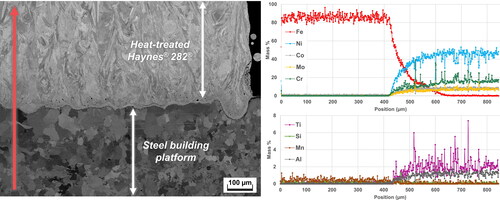
Line scans by EDX analysis across the interface region showed a gradient of chemical composition at this region. The length of the line scan was 800 µm, starting from the steel and ending in the Haynes® 282®. Fe was the only major element found in the building platform, along with some amount of Si and Mn. The interface region was found at approximately 400 µm. An increase in elements comprising Haynes® 282®, and corresponding decrease in Fe, was observed after the 400 µm location up until 600 µm, after which the elements comprising Haynes® 282® normalized, and Fe reduced to nearly zero. Within this transition zone, opposing peaks of Fe and Ni can be observed in the line scan results, e.g., at 420 µm and at 500 µm (see ).
Figure 5. EDX line scan analysis of interface region between LPBF Haynes® 282® and steel building platform in as-built condition. Red arrow indicates direction of line scan.
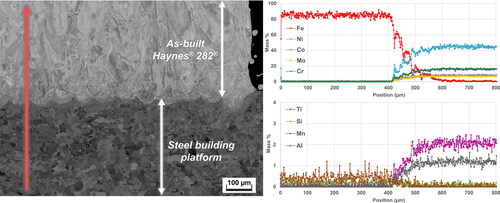
Note that analysis results of C and other minor elements are not shown due to the limitation of EDX analysis to reliably measure and quantify those elements. It is also pertinent to disclose that quantification of EDX analysis spectra is performed on a comparative basis, and the values of mass % presented in and should only be scrutinized relative to other values in the same analysis, and not as absolute values.
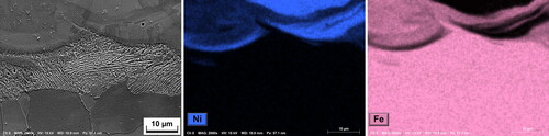
EDX mapping of the Ni and Fe content in this region presented a clearer picture of the arrangement of chemical elements in the interface. The map showed that the steel and Haynes® 282® were coarsely mixed within individual melt tracks, and no homogenization had taken place. shows the layered structure where a sharp difference in concentrations of Ni and Fe are observed at different regions within the melt tracks.
Figure 6. EDX analysis of interface region between LPBF Haynes® 282® and steel building platform in as-built condition.
Heat-treated material
The size of the interface region after heat treatment was found to be similar to the material in the as-built condition, i.e. approximately 200 µm. The corresponding EDX line scan analysis is shown in . It was observed that the gradients of Ni and Fe content over the interface region were smoothened, showing that homogenization of the chemical composition had taken place. This was confirmed with EDX maps of the interface region—see . Formation of carbides at grain boundaries was also observed, and can be seen from peaks of Cr, Ti, and Mo in the EDX line scan analysis—e.g. at 600 µm and 730 µm. The formation and characterization of carbides at grain boundaries in Haynes® 282® in reaction to heat treatment has been covered in detail in other works (Boswell et al., Citation2021; Ghiaasiaan, Ahmad, Gradl, Shao, & Shamsaei, Citation2022; Shaikh, Schulz, Minet-Lallemand, & Hryha, Citation2021).
Figure 7. EDX line scan analysis of interface region between LPBF Haynes® 282® and steel building platform after heat treatment.
It is notable that no enlargement of the region of compositional gradient was observed after heat treatment. Furthermore, there was no evidence of significant diffusion of alloying elements (excluding minor elements not detectable by EDX) from Haynes® 282® into the steel building platform. Nominal levels of alloying elements in the Haynes® 282® after the transition region appear to be the same before and after heat treatment.
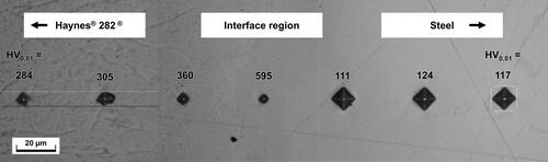
The microstructure of the interface region was altered after heat treatment, as shown in . On the side of the Haynes® 282® alloy, large blocky carbides were observed at the grain boundaries. The steel directly adjacent to the interface region showed larger grains than before (compare with ), with no apparent pearlite structures. Carbon-rich rims of around 5 to 10 µm in width at the Ni-alloy/steel building platform interface were observed where the melt pool boundaries had previously been found, as shown in . This microstructure also showed a high hardness in comparison to the material around it (see ).
Figure 8. Microstructure of the interface region after heat treatment.
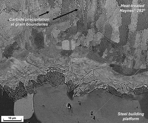
Figure 9. Microstructure and EDX analysis of interface region between Haynes® 282® and steel building platform after heat treatment.
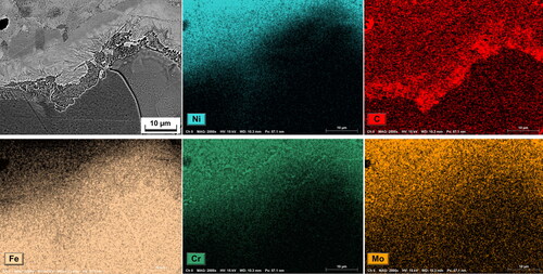
Figure 10. Hardness variation along the interface region after heat treatment.
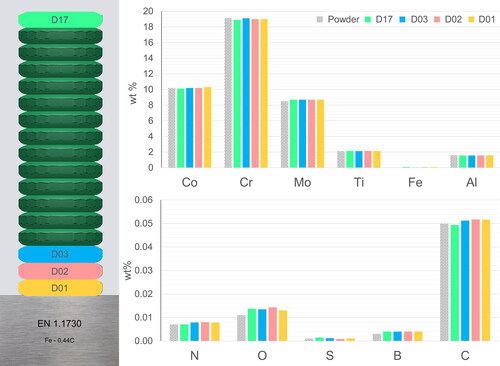
The stacked disc samples represent the material at different build heights, with a low disc number (e.g., D01, from 0 mm to 3 mm build height) representing material close to steel platform, and a higher number (e.g., D17, from 48 mm to 51 mm build height) representing material at the top of the build height. Analysis of the chemical composition of the Haynes® 282® after heat treatment using these disc samples showed no significant deviation of the chemical composition from the composition of the powder. Most importantly, no large increase in Fe content was found. Complete results are displayed in . No significant difference between the top (D17) and bottom (D01) of the build could be observed. Minor elements were also analyzed, and the difference between the chemical composition of different discs was also small, and within the accuracy of the measurement techniques, suggesting that no detectable contamination from the building platform took place during heat treatment.
Figure 11. Chemical composition analysis results of stacked disc samples at different locations along the build height.
Mechanical properties
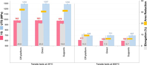
Tensile testing was performed with samples heat treated in several different conditions: (i) samples heat treated only after removal from the platform, (ii) samples heat treated while having a direct connection to the platform, and (iii) samples heat treated while connected to the platform by support structures. Note that samples which were removed from the platform before heat treatment were built in a separate print job and are not shown in . A summary of the values of the yield stress (YS), ultimate tensile stress (UTS), elongation at fracture, and area reduction at fracture for the different sample conditions is given in . At room temperature average YS of 982 MPa, 983 MPa, and 976 MPa were achieved for the samples heat-treated off-platform, samples heat treated with direct connection to the platform, and samples heat treated with connection to the platform via supports, respectively. Similarly, small differences were observed in the UTS. Elongation at fracture averaged between 19,8% and 20,6%. At 800°C, the samples heat-treated off-platform showed slightly higher average values of elongation at fracture and YS than the samples heat treated while connected to the platform either directly or by supports. However, no drastic differences in strength and ductility could be observed in the tensile testing results.
Figure 12. Mechanical properties of horizontally manufactured Haynes® 282® tensile bars at room temperature and 800 °C. “Direct” indicates that samples were heat treated with direct connection to platform. “Supports” indicates that samples were heat treated while connected to the platform by supports. “Off-platform” indicates that samples were heat treated after removal from the platform. YS = Yield stress, UTS = Ultimate tensile stress.
Discussion
Small-scale effects at the interface region
Analysis of the microstructure of the interface region in the as-built condition showed that full mixing of steel and Ni-alloy has not been achieved. The EDX maps shown in indicate that there are large-scale regions of steel that have been melted and transported within the individual melt tracks during the LPBF process, but mixing has not taken place. These structures have also been observed in other dissimilar metal welding pairs and have been termed as “island” structures by Yang et al. (Guo et al., Citation2022; Yang & Kou, Citation2007). This incomplete mixing may be a consequence of the different melting/freezing temperatures and densities of the two materials, along with the rapid cooling rates that are inherent in the LPBF process (Hocine et al., Citation2020).
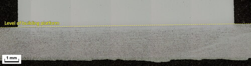
The interface region was found to be around 200 µm in width. However, the center point of the interface region was not aligned with the surface of the building platform, but rather, most of the interface region was found to be below the level of the building platform, as shown in . This is probably due to the “Strong Platform Connection” feature in EOS LPBF processes, which melts the first layer of the build twice, to strengthen the bonding between the building platform and the built-up part. This feature was enabled for the building process in this study.
Figure 13. Macrograph showing interface region as being mainly below the level of building platform.
The size of the interface region did not change significantly after the heat treatment and remained close to 200 µm. However, the distribution of steel and Ni-alloy alloying elements were largely homogenized across the interface region, i.e. unmixed Fe and Ni bands in individual melt tracks were no longer found. Several features of the heat-treated interface region were found to be familiar from reports of carbon steel to Ni-alloy weld fusion zones present in literature, and are explained in the following paragraphs.
Depletion of carbon from the steel building platform in the vicinity of the interface region and pile-up at the interface/fusion zone has been found, as shown in and , which is consistent with other reports (Ahonen et al., Citation2020; da Silva Lima et al., Citation2021). According to DuPont the migration of C is due to its affinity for the higher Cr contents found within the interface region (DuPont, Kiser, & Lippold, Citation2009). The large steel grains observed close to the fusion zone are likely to be a consequence of the high solution and ageing temperatures experienced by the material during the heat treatment.
The increased alloying element content in the steel side of the interface region, coupled with the high hardness, and acicular morphology of microstructure seen there, suggests formation of a hard and brittle phase, possibly martensite. This is likely to be tempered during the ageing steps of the heat treatment, however results in show that the phase is still extremely hard. The formation of a thin layer of martensite at the interface between carbon steel and Ni-alloy welds is a well-documented occurrence in welding literature (Ahonen et al., Citation2020; DuPont et al., Citation2009). It is suggested that the side of the fusion zone with more Fe, Cr, and C forms martensite, whereas the side with more Ni stays austenitic.
Above the interface region the microstructure of the Haynes® 282® was seen to be largely consistent with the description of heat-treated LPBF Haynes® 282® microstructure from previous studies. However, the large blocky carbides appearing immediately adjacent to the interface region (see ) are larger and more numerous than observed in other works (Ghiaasiaan et al., Citation2022; Shaikh et al., Citation2021), and suggest a local increase in the C content. Such a local increase in carbide precipitation was also reported by Lopez et al. regarding a dissimilar metal weld of AISI 4130 and Inconel 625 (López, Gutiérrez, & Urcola, Citation1996).
Large-scale effects
The microstructural features discussed in the previous section have limited importance for the quality of the LPBF build, as they occur below the level of the final printed part. As described in , in a typical manufacturing process flow the printed part will be separated from the platform by a cutting process, which will remove a certain amount of material (kerf) at the bottom of the build. Wire EDM is the most common cutting process, where the kerf width is around 300 µm or more (Abinash, Siddhartha, & Mandal, Citation2011). Bandsaws may also be used, which have typical kerf widths of around 1.6 mm (American Society of Materials, Citation1989). In case of either of these cutting processes, the affected interface region and adjacent microstructure is likely to be removed from the final part.
The composition analysis results from stacked disc samples are therefore more representative of the printed material at a larger scale. These results show no significant change in chemical composition from the original composition of the powder. Importantly, all elements are within the limits for Haynes® 282® set out in AMS 5951A (this standard is used as a reference even though it is for wrought material, as currently there is no available standard for additively manufactured Haynes® 282®) (SAE International, Citation2010–12). No depletion of the gamma prime forming elements or oxide forming Cr was found. Deleterious elements like S also stayed at the low level of around 10 ppm, similar to what was found in the powder. Note that Haynes® 282® has a maximum limit for Fe of 1.5 wt% (SAE International, Citation2010–12), and the Fe contents stayed below 0.1 wt% in all samples analyzed. A low tolerance alloy such as Haynes® 282® was specifically chosen for this study, as other common AM Ni-base alloys typically are Ni-Fe base (e.g., Inconel 718 and Hastelloy® X) and even Inconel 625 can contain up to 5 wt% of Fe. It is expected that these results should be relevant for other Ni alloys printed on steel platforms as well. It is also worth noting that this study has used a full three step solution and double ageing heat treatment, which gives much more time for diffusion of contaminating elements than a short stress relief that is typically used in industry (Gola, Dubiel, & Kalemba-Rec, Citation2020). Therefore, this study represents a worse case condition than what would be encountered in real world manufacturing practice.
The fact that the chemical composition results show no change in composition, whereas EDX results show a significant gradient in composition may seem like a discrepancy. This can be reconciled by considering that (i) the chemical composition results are from a larger volume of material (several cubic mm) as described in the Materials and Methods section; and (ii) that the lowest stacked disc D01 was separated from the building platform using a precision metallographic saw, which would have removed any interface region and compositional gradient that may have existed.
Mechanical testing results also showed that heat treatment of samples with full connection to the platform has no appreciable effect on mechanical properties. A slightly better ductility achieved at 800°C by samples heat-treated off-platform is expected to be because these samples were built in a separate print job which had smaller number of samples and different layout of parts over the platform. The similarity in mechanical test results across different conditions is expected due to the lack of change in chemical composition shown earlier, and because any affected material would be removed from the tensile test bars during machining of samples. Nevertheless, these results are important evidence that mechanical performance is largely unaffected by off-platform heat treatment, or heat treatment on-platform (either through supports or direct connection).
None of the results in this study so far suggest any reason to avoid the use of steel building platforms in LPBF of Ni-base superalloys. However, there may be non-metallurgical reasons for using platforms that match the building material. One example could be a case where the alloy being printed has sufficiently different thermal expansion properties to the building platform which would otherwise cause uneven expansion and contraction during heat treatment and thus damage to the part or platform. Another case could be material combinations where detrimental phases form at the interface, leading to defects or potential separation of the part from the platform during the build. The material pairing may also be of relevance for multi-material AM, or for repair applications where a dissimilar material is printed onto an existing part. In such cases, the interface region becomes relevant as it is an integral part of the component, instead of being removed after stress relief.
Conclusions and recommendations
In this study, a Ni-base superalloy Haynes® 282® was printed by LPBF onto a carbon steel building platform, and heat treated while connected to the platform to elucidate the extent and effect of possible contamination by diffusion of unwanted alloying elements from the building platform. Based on the results obtained, the following conclusions can be made:
There is no large-scale change in chemical composition of the LPBF material in as-built or heat-treated condition (even after a full solution plus double ageing heat treatment). No contamination of Fe or deleterious elements could be detected, and the composition of Haynes® 282® remained within standard specification requirements.
An interface region of approximately 200 µm width was observed between the LPBF Haynes® 282® and the steel building platform. The location of the interface is slightly below the level of the building platform, and no enlargement of the interface region was observed in response to heat treatment. It is expected that any cutting process used to separate the printed part from the building platform would remove this interface region.
Performing heat treatment either while parts are connected to the platform, or after removal of the parts, does not have a significant effect on the tensile properties at room temperature or 800°C.
In light of these conclusions, it follows that steel building platforms are feasible to use for Ni-alloy LPBF builds, in particular that there are no apparent metallurgical reasons to avoid their use. The authors recommend that when separating built parts from building platform it may be advisable to use cutting methods that remove the first 200 µm of built-up material.
Author contributions
Abdul Shaafi Shaikh: Conceptualization, Investigation, Formal Analysis, Validation, Writing—Original Draft, Visualization. Fiona Schulz: Conceptualization, Validation, Formal Analysis, Investigation, Writing—Review and Editing. Kevin Minet-Lallemand: Conceptualization, Methodology, Resources, Supervision, Writing—Review and Editing, Project Administration, Funding Acquisition. Eduard Hryha: Supervision, Resources, Validation, Writing—Review and Editing, Project Administration, Funding Acquisition.
Acknowledgements
The authors gratefully acknowledge assistance from Dmitri Riabov of Höganäs AB in chemical composition analysis.
Disclosure statement
The authors report there are no competing interests to declare.
Additional information
Funding
Notes on contributors
Abdul Shaafi Shaikh
Abdul Shaafi Shaikh is a materials engineer and industrial doctoral student at EOS Metal Materials and Chalmers University of Technology. His research focuses on additive manufacturing (3D printing) of nickel-base superalloys for high temperature applications. Shaafi’s research is conducted as part of the CAM2 competence centre for additive manufacturing.
Fiona Schulz
Dr. Fiona Schulz is a researcher in metal additive manufacturing at Chalmers University of Technology as part of CAM2. Her research focuses on investigating process–structure–property relationships of high-temperature, high-performance materials.
Kevin Minet-Lallemand
Kevin Minet-Lallemand is a materials scientist and Technology Development Manager at EOS Metal Materials in Finland, focusing on developing new metal materials and processes for Laser Powder Bed Fusion Additive Manufacturing. He has more than a decade of experience in process development, powder analysis, and statistical process control of additive manufactured Ni-base superalloys.
Eduard Hryha
Professor Eduard Hryha is a researcher in powder metallurgy and metal additive manufacturing. His research focuses on powder metallurgy, powder-based metal additive manufacturing, surface analysis using advanced surface-sensitive techniques, as well as thermal analysis. He is also director of CAM2 competence centre focusing on powder-based metal additive manufacturing.
References
- Abinash, K. S., Siddhartha, R., & Mandal, N. K. (2011). Study on Kerf width in wire-EDM based on Taguchi method. Applied Mechanics and Materials, 110–116, 1808–1816. doi:10.4028/www.scientific.net/AMM.110-116.1808
- Ahonen, M., Mouginot, R., Sarikka, T., Lindqvist, S., Que, Z., Ehrnstén, U., … Hänninen, H. (2020). Effect of thermal ageing at 400 °C on the microstructure of ferrite-austenite interface of nickel-base alloy narrow-gap dissimilar metal weld. Metals, 10(3), 421. doi:10.3390/met10030421
- American Society of Materials. (1989). Machining—ASM handbook (Vol. 16). Material Park, OH: ASM International
- Boswell, J., Jones, J., Barnard, N., Clark, D., Whittaker, M., & Lancaster, R. (2021). The effects of energy density and heat treatment on the microstructure and mechanical properties of laser additive manufactured Haynes 282. Materials & Design, 205, 109725. doi:10.1016/j.matdes.2021.109725
- da Silva Lima, C. V., Verdier, M., Robaut, F., Ghanbaja, J., Badinier, G., Marlaud, T., … Van Landeghem, H. P. (2021). Evolution of a low-alloy steel/nickel superalloy dissimilar metal weld during post-weld heat treatment. Welding in the World, 65(10), 1871–1885. doi:10.1007/s40194-021-01146-8
- DIN EN ISO. (2018). DIN EN ISO 683-1:2018-09, Für eine Wärmebehandlung bestimmte Stähle, legierte Stähle und Automatenstähle_- Teil_1: Unlegierte Vergütungsstähle (ISO_683-1:2016); Deutsche Fassung EN_ISO_683-1:2018: Heat treatable steels, alloy steels and freecutting steels - Part 1: Nonalloy steels for quenching and tempering. Berlin: Beuth Verlag GmbH.
- DuPont, J. N., Kiser, S. D., & Lippold, J. C. (2009). Welding metallurgy and weldability of nickel-base alloys. Hoboken, New Jersey: Wiley.
- Geddes, B., Leon, H., & Huang, X. (2010). Superalloys: Alloying and performance. Materials Park, OH: ASM International
- Ghiaasiaan, R., Ahmad, N., Gradl, P. R., Shao, S., & Shamsaei, N. (2022). Additively manufactured Haynes 282: Effect of unimodal vs. bimodal γ’- microstructure on mechanical properties. Materials Science and Engineering: A, 831, 142234. doi:10.1016/j.msea.2021.142234
- Gola, K., Dubiel, B., & Kalemba-Rec, I. (2020). Microstructural changes in inconel 625 alloy fabricated by laser-based powder bed fusion process and subjected to high-temperature annealing. Journal of Materials Engineering and Performance, 29(3), 1528–1534. doi:10.1007/s11665-020-04605-3
- Guo, X., He, P., Xu, K., Lv, X. C., Zhang, J. B., & Gu, Y. (2022). Microstructure investigation on the fusion zone of steel/nickel-alloy dissimilar weld joint for nozzle buttering in nuclear power industry. Welding in the World, 66(2), 187–194. doi:10.1007/s40194-021-01199-9
- Haynes International Inc. (• • • •). HAYNES® 282®Alloy [Internet] (2022). Retrieved 2022, from https://haynesintl.com/alloys/alloy-portfolio_/High-temperature-Alloys/HAYNES282alloy.aspx.
- Hocine, S., Van Swygenhoven, H., Van Petegem, S., Chang, C. S. T., Maimaitiyili, T., Tinti, G., … Casati, N. (2020). Operando X-ray diffraction during laser 3D printing. Materials Today, 34, 30–40. doi:10.1016/j.mattod.2019.10.001
- López, B., Gutiérrez, I., & Urcola, J. J. (1996). Microstructural analysis of steel–nickel alloy clad interfaces. Materials Science and Technology, 12(1), 45–55. doi:10.1179/mst.1996.12.1.45
- Osgerby, S., & Gibbons, T. B. (1992). The effect of trace elements on the creep behaviour of an Ni-Cr-base alloy. Materials Science and Engineering: A, 157(1), 63–71. doi:10.1016/0921-5093(92)90099-M
- SAE International. (2010–12). AMS5951A for Haynes 282: Nickel alloy, corrosion and heat-resistant, sheet, strip, and plate 57Ni-20Cr-10Co-8.5Mo-2.1Ti-1.5Al-0.005B vacuum induction and consumable electrode melted, solution heat treated precipitation heat treatable. Amsterdam, Netherlands: SAE International.
- Shaikh, A. S., Schulz, F., Minet-Lallemand, K., & Hryha, E. (2021). Microstructure and mechanical properties of Haynes 282 superalloy produced by laser powder bed fusion. Materials Today Communications, 26, 102038. doi:10.1016/j.mtcomm.2021.102038
- Sims, C. T., Stoloff, N. S., & Hagel, W. C. (1987). Superalloys II: High-Temperature Materials for Aerospace and Industrial Power. New York: Wiley.
- Yang, Y. K., Kou, S. & Yang, (2007). Fusion-boundary macrosegregation in dissimilar filler metal Al Cu welds. Welding Journal, 86, 331s–339s. Available from: http://files.aws.org/wj/supplement/WJ_2007_11_s331.pdf.