
Medical imaging is rapidly evolving from 2D to 3D discipline. The current imaging technology moves beyond the 2D paradigm, increasingly using virtual and physical reconstruction of 3D objects from volumetric imaging data. 3D printing, also known as rapid prototyping or additive manufacturing, provides a fast and accurate means for translating volumetric anatomic data into 3D objects. Within a decade, 3D printing has already demonstrated value in aiding diagnosis and planning surgical and interventional procedures [Citation1–4].
High costs and technical challenges have been the major barriers preventing the meaningful adoption of 3D printing in contemporary medical practices. However, improved technology has led to more cost-effective and user-friendly platforms, allowing increasing availability to a wide range of medical professionals and new opportunities to improve patient care [Citation5,Citation6]. In this study, we showcase an affordable and practical fabrication technique for creating anatomically accurate vascular models, utilizing an affordable desktop 3D printer, for preoperative planning and training.
Any volumetric imaging modality capable of differentiating tissue types can be used to create a 3D model. However, the data must be optimized to the end goals of the builder. Technical characteristics, such as tissue contrast, artifacts and signal-to-noise, determine the utility of a particular imaging technique for building a prototype. Currently, the ubiquity, fast acquisition times and superior spatial resolution of multidetector CT make this the most common modality chosen for most medical prototypes, with magnetic resonance, x-ray angiography and ultrasound used less frequently. Images using isotropic voxels of 1.25 mm or less are ideal [Citation7]. Thicker image sections (5.0 mm) can compromise spatial accuracy, while very thin sections (0.25 mm) may require extensive software processing and manipulation before printing.
3D printers are not directly compatible with Digital Imaging and Communications in Medicine (DICOM) data. Instead, printers use a universal file format called Standard Tessellation Language (STL), relying on a collection of adjacent triangles enclosing a region of space which the printer uses to construct the 3D model. A conversion platform is therefore necessary to facilitate the translation from DICOM image data to printable STL files, isolating the desired structure while maintaining anatomic accuracy. Available software ranges from ‘freeware’ applications such as 3D Slicer to proprietary software for purchase such as Mimics InPrint 2.0 (Materialise, Leuven, Belgium). After STL file generation, further postprocessing with computer-aided design software is required. This is sometimes performed using proprietary software designed for the printer itself.
Numerous printing methodologies have been developed, which continue to rapidly evolve. Some of the most commonly used in medical 3D printing are demonstrated in . An extensive variety of printers are available. Large machines with superior resolution, high efficiency and multimaterial capability can quickly print more sophisticated and precise objects, but require greater capital investment. In contrast, smaller printers with increasingly good resolution are becoming available, at more affordable prices. In , we juxtapose costs and specifications of a smaller desktop printer used in our project versus more expensive printers which might be found in an advanced medical 3D lab.
Table 1. Overview of several common 3D printing methods.
Table 2. An affordable desktop printer Form 2 (Formlabs) was used for our project. More expensive printers with larger build volumes, better resolution and/or greater material flexibility might be found in a large hospital 3D lab.
Technique
Multidetector computed tomography angiography (CTA) of the chest, abdomen and pelvis was selected from a patient with a healthy aorta. The patient data were acquired on a 64-slice Philips Brilliance CT system (Brilliance 64®, Philips Medical Systems, Eindhoven, The Netherlands) with parameters of 0.625 mm collimation, 120 kVp, 20–500 mA using automatic exposure control, pitch of 0.9 and a reconstructed section thickness of 2 mm with 1 mm overlap. Contrast medium enhancement was achieved with intravenous infusion of 120 ml Isovue 370 (Bracco, Milan, Italy) at a rate of 4.5 ml/s. Density in the thoracic aortic lumen measured approximately 300 HU. Axial DICOM files were ordered sequentially and uploaded to Mimics InPrint 2.0 software (Materialise).
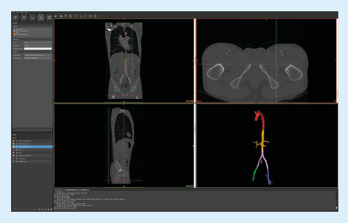
CTA data were processed using Mimics InPrint 2.0 software. Density thresholding was applied to identify the region of interest in the contrast-filled arterial system. The desired lumen was isolated and the extra-arterial structures removed. The software was used to smoothen the solid part (in this case contrast in the arterial lumen), correcting for artifacts and image noise. An external wall was then applied around the isolated arterial lumen and to the ends of each vessel to generate a closed-end model. Wall thickness was minimized to 1 mm to preserve luminal integrity of the smaller branch vessels. We used the software to virtually slice the complete model into multiple smaller components, with sizes based on printer build volume of 17.5 × 14.5 × 14.5 cm3. Separated components are shown color coded, each representing a separate STL file ().
Color-coded segments (bottom right) were virtually cut to fit our printer's build volume.
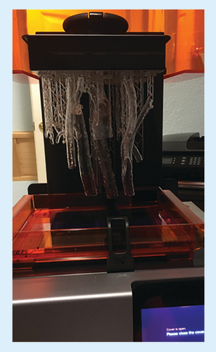
We used Form 2 (Formlabs, MA, USA), a stereolithography printer. STL files generated in Step 2 were manipulated using Form 2's computer-aided design software for placement within the printer 3D build volume of 145 × 145 × 175 mm3. Two separate prints of 8 h and 12 h with a total of 20 h were required to print all model parts (). The printer software generated support scaffolding to stabilize the print during the build process as the printer utilizes a UV laser with a spot size of 140 microns to cure liquid resin layer by layer with layer thickness in axis resolution of 25, 50 and 100 microns.
STL files manipulated using Form 2's CAD software for placement within the printer 3D build volume. Two separate prints of 8–12 h each were required to print all model parts.
CAD: Computer-aided design; STL: Standard Tessellation Language.
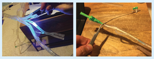
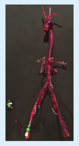
Printed material was separated from the printer base and support material carefully removed. Parts were washed in isopropyl alcohol solution to remove uncured resin from the model surface. After cleaning, the separate components were fused together by painting liquid resin onto the joints and curing the resin with a handheld UV laser carefully to ensure a precise fit between the components (A). Protective glasses are an important precaution when manually fusing any model parts with the handheld laser to prevent eye injury. Finally, the model was filled with water to simulate a more realistic tactile environment and a hole was drilled in desired access location for a 6 French vascular access sheath to be inserted. The access sheath was secured in water-tight fashion, using the laser fusion technique (B). A larger sheath could be used if a larger access hole was manually drilled into the desired location.
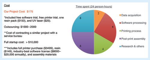
Our project was completed at a cost of $175, which included the free trial of Mimics InPrint 2.0 software, free trial of Form 2 printer (Formlabs), a resin pack of $150 and the UV laser of $25. Contracting out to a fee-for-service partner might have cost US$1000–2000, depending on specifications. Full printer purchase and an annual software license would have exceeded $10,000. A sum of 24 person-hours was required with 2 person-hours spent on data acquisition, 6 person-hours on software processing, 4 person-hours on printing process, 6 person-hours on post-print assembly and 6 person-hours on research and troubleshooting as summarized in .
Parts were washed in isopropyl alcohol solution to remove uncured resin from the model surface. The components were fused by painting liquid resin onto the joints, and curing with a handheld UV laser (A). The model was filled with water and vascular access sheaths were secured (B).
Discussion
Our work demonstrated the feasibility of fabricating 3D-printed patient-specific vascular model (). The completed patient-specific model was successful, but the segmentation accuracy was limited by the resolution of the CTA imaging with 1 mm overlap approximately one imaging voxel size which had to be smoothed in mesh cleanup. We propose that subsequent iterations of patient-specific model fabrication be evaluated for geometry accuracy to the patient's anatomy. Image acquisition of the fabricated model can be obtained and compared with the original patient data. Difference comparisons can be visually demonstrated through a colored map and histogram as exemplified by Ionita et al. [Citation8]. Using the Form 2 printer, the design is limited to a build volume of 145 × 145 × 175 mm3 resulting multiple modular components to maintain the 1:1 scale between the model and patient anatomy. Challenging anatomic areas included the aortic arch, where streak artifact from contrast in the superior vena cava necessitated some processing corrections. Small branch vessels required careful irrigation after printing to avoid luminal occlusion of the small vessels by uncured resin. Minimizing wall thickness to 1 mm allowed patency of smaller branch vessels but sacrificed overall durability.
Although our presented workflow to create a patient-specific vascular model using Form 2 3D printer has its challenges, it eliminates and simplifies certain aspects of the patient-specific model fabrication process. Previously reported patient-specific vascular models were difficult to produce despite their simplified structures [Citation9–12]. Although the simplified patient-specific models permitted the evaluation of procedural devices, the simulation value of the intervention diminishes without a realistic patient-specific vascular model for practice. To further mimic the characteristics of vasculature, flexible materials such as flexible photoresins should be considered as several case studies have documented the feasibility of using 3D-printed flexible photopolymers for vascular models with initial quantification of material characteristics of compliance, stiffness and pressure distributions [Citation13–16].
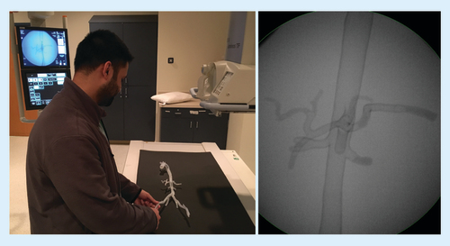
A variety of applications exist for anatomic arterial models. The opportunities we found most attractive included student and resident training (A & B), procedural planning and patient education. In addition to being a diagnostic tool, the model allowed one to simulate an endovascular procedure with device testing in a risk-free environment without harm to patient. Rapid prototyped patient-specific vascular models have been used to visualize complex anatomies and to practice procedures to improve clinical interventional training and reduce the risk of procedural complications [Citation17–20]. However, one should take into consideration the limitations of the 3D-printed models during training as they may not have the same flexibility, resistance, wall fragility and endovascular flow of a real arterial system.
A resident practicing catheter skills (A), with corresponding fluoroscopic image of the training model (B).
Future perspective
With advancements in medical imaging and 3D printing technology, fabrication of patient-specific models for procedural planning by the clinical team is feasible. Inexperienced users can explore incorporating 3D vascular prototypes in clinical practice, without initially committing to the capital requirements of a dedicated 3D lab. Printing subcomponent parts and manually assembling a larger model take time, but provides substantial cost savings over larger and more advanced printers. Free or discounted software trials can also help minimize expenses. Our costs totaled $175. The project was achievable in 24 person-hours, given proper equipment, reference materials and some occasional problem solving. The final vascular model was produced cost effectively while maintaining quality and utility for teaching, procedural planning and patient education to enhance patient care.
Background
3D-printed models of patient-specific vascular structures can be fabricated in an affordable and practical manner to create anatomically accurate for preoperative planning and training.
Technique
Data acquisition
Computed tomography angiography of the chest, abdomen and pelvis was selected from a patient with a healthy aorta.
Data processing
Computed tomography angiography data were processed using Mimics InPrint 2.0 software (Materialise, Leuven, Belgium) for segmentation and Standard Tessellation Language file generation.
3D printing
Standard Tessellation Language files were manipulated and 3D printed using Form 2 computer-aided design software and printer (Formlabs, MA, USA).
Post-processing
3D-printed parts were fused and filled with water, and vascular access sheaths were placed for hands-on training.
Cost and time analysis
Total cost and time requirements were broken down and summarized.
Discussion
Completed 3D model
Total cost was $175 and an estimated 24 person-hours were required.
Anatomically accurate with 1 mm order of error.
Applications in interventional radiology
The 3D model allowed for student and resident training, procedural planning and patient education.
Future perspective
3D printing of custom vascular models will become more cost effect and ubiquitous to aid procedural planning, simulated training and patient education to enhance patient care in vascular and interventional radiology.
Acknowledgements
The authors would like to acknowledge Materialise for assisting with data segmentation and processing as well as Formlabs for sponsoring the Form 2 printer use for this project.
Financial & competing interests disclosure
The authors have no relevant affiliations or financial involvement with any organization or entity with a financial interest in or financial conflict with the subject matter or materials discussed in the manuscript. This includes employment, consultancies, honoraria, stock ownership or options, expert testimony, grants or patents received or pending, or royalties.
No writing assistance was utilized in the production of this manuscript.
References
- Rengier F , MehndirattaA, von Tengg-KobligkHet al. 3D printing based on imaging data: review of medical applications. Int. J. Comput. Assist. Radiol. Surg.5(4), 335–341 (2010).
- Green DE , McNeeleyMF. Practice corner: a perfect fit. Radiographics32(7), 1975–1976 (2012).
- Tam MD , LaycockSD, BrownJR, JakewaysM. 3D printing of an aortic aneurysm to facilitate decision making and device selection for endovascular aneurysm repair in complex neck anatomy. J. Endovasc. Ther.20(6), 863–867 (2013).
- Itagaki MW . Using 3D printed models for planning and guidance during endovascular intervention: a technical advance. Diagn. Interv. Radiol.21(4), 338–341 (2015).
- Mitsouras D , LiacourasP, ImanzadehAet al. Medical 3D printing for the radiologist. Radiographics35(7), 1965–1988 (2015).
- Sheth R , BaleshER, ZhangYS, HirschJA, KhademhosseiniA, OkluR. Three-dimensional printing: an enabling technology for IR. J. Vasc. Interv. Radiol.27(6), 859–865 (2016).
- Mahesh M . Search for isotropic resolution in CT from conventional through multiple-row detector. Radiographics22(4), 949–962 (2002).
- Ionita CN , MokinM, VarbleNet al. Challenges and limitations of patient-specific vascular phantom fabrication using 3D Polyjet printing. Proc. SPIE Int. Soc. Opt. Eng.9038, 90380M (2014).
- Sherman J , RangwallaH, DohatcuA, MinsuokK, IonitaC, RudinS. SU-FF-I-127: patient specific angiography phantoms for investigating new endovascular image-guided interventional (EIGI) devices. Med. Phys.34(6), 2367 (2007).
- Sherman J , RangwalaH, IonitaCet al. Investigation of new flow modifying endovascular image-guided interventional (EIGI) techniques in patient-specific aneurysm phantoms (PSAPs) using optical imaging. Proc SPIE Int. Soc. Opt. Eng.6918, 69181v (2008).
- Schafer S , HoffmannKR, NoëlPB, IonitaCN, DmochowskiJ. Evaluation of guidewire path reproducibility. Med. Phys.35(5), 1884–1892 (2008).
- Ionita CN , SuriH, NataranjianSet al. Angiographic imaging evaluation of patient-specific bifurcation-aneurysm phantom treatment with pre-shaped, self-expanding, flow-diverting stents: feasibility study. Proc. SPIE Int. Soc. Opt. Eng.7965, 79651H1–79651H9 (2011).
- Meess KM , IzzoRL, DryjskiMLet al. 3D Printed abdominal aortic aneurysm phantom for image guided surgical planning with a patient specific fenestrated endovascular graft system. Proc. SPIE Int. Soc. Opt. Eng.11, 10138 (2017).
- Cloonan AJ , ShahmirzadiD, LiRX, DoyleBJ, KonofagouEE, McGloughlinTM. 3D-printed tissue-mimicking phantoms for medical imaging and computational validation applications. 3D Print. Addit. Manuf.1, 14–23 (2014).
- de Galarreta SR , AitorC, AntónR, FinolEA. Abdominal aortic aneurysm: from clinical imaging to realistic replicas. J. Biomech. Eng.136, 014502 (2014).
- Biglino G , VerschuerenP, ZegelsR, TaylorAM, SchievanoS. Rapid prototyping compliant arterial phantoms for in-vitro studies and device testing. J. Cardiovasc. Magn. Reson.15, 2 (2013).
- Perrin D , BadelP, OrgeasLet al. Patient-specific simulation of endovascular repair surgery with tortuous aneurysms requiring flexible stent-grafts. J. Mech. Behav. Biomed. Mater.63, 86–99 (2016).
- Erbano BO , OpolskiAC, OlandoskiMet al. Rapid prototyping of three-dimensional biomodels as an adjuvant in the surgical planning for intracranial aneurysms. Acta. Cir. Bras.28(11), 756–761 (2013).
- Winder RJ , SunZ, KellyB, EllisPK, HirstD. Abdominal aortic aneurysm and stent graft phantom manufactured by medical rapid prototyping. J. Med. Eng. Technol.26(2), 75–78 (2002).
- Markl M , SchumacherR, KüfferJ, BleyTA, HennigJ. Rapid vessel prototyping: vascular modeling using 3t magnetic resonance angiography and rapid prototyping technology. MAGMA18(6), 288–292 (2005).