
Abstract
Aim: To test 3D-printed immobilization devices for future use in magnetic resonance-guided focused ultrasound hyperthermia. Material & methods: Using a surface scanner, patient-specific pelvic immobilization devices were 3D printed. The setup reproducibility was measured both on linear accelerator (LINAC) and magnetic resonance. An ultrasound imaging probe was used to acquire reference images and later to acquire images once attached into the embedded holder. Results: Prepositioning accuracy was tested at LINAC using an optical surface monitoring and MRI and showed submillimeter accuracy and small angular rotations. Agreement was high between the ultrasound reference images versus the immobilized probe. Conclusion: Reported results are considered as a promising step toward a fast and precise positioning of patients and an easier integration of radiotherapy and magnetic resonance-guided focused ultrasound hyperthermia.
Plain language summary
Local hyperthermia it is clinically accepted as a synergistic adjunct to cancer radiation therapy (RT) and consists of a small local temperature increase. Hyperthermia and RT require patient immobilization and excellent spatial control over repeated sessions. To this purpose, we employed the modern technologies of stereoscopic surface scanning and 3D printing of rigid objects, aiming to improve RT outcomes in cancer fighting patients.
External beam radiotherapy (EBRT) is the gold standard salvage treatment for patients experiencing a biochemical relapse after radical prostatectomy [Citation1]. Although it has been improved for selected patients by combining androgen deprivation [Citation2,Citation3], the long-term disease control remains limited, with approximately 50% of the patients presenting a disease progression at 5 years [Citation4]. In analogy with clinical prospective phase III trials of radical EBRT for localized prostate cancer, dose escalation is used to improve outcome even in the setting of salvage radiotherapy, although long-term toxicities may be increased especially when the radiotherapy doses exceed 70 Gy [Citation5–8].
More compelling treatment approaches able to improve the therapeutic ratio in the salvage setting are therefore needed, especially for patients harboring a macroscopic relapse in the prostate bed [Citation5]. Hyperthermia (HT) [Citation9] with radiation is a promising treatment modality relying on well-established rationale [Citation10] and clinical data [Citation11–13]. By increasing the temperature of the targeted region to values between 41° and 43°, deep HT combined with EBRT could improve the cell killing [Citation14–16] and potentially reduce side effects by avoiding the need of dose escalation or androgen deprivation.
With its capacity to sharply deposit energy inside deep tissues, magnetic resonance-guided focused ultrasound technology (MRgFUS) employing modern phased array transducers has been proposed as a promising technology for deep HT [Citation17,Citation18]. In the last decade the number of potential applications of this technology has rapidly increased with multiple studies proving its application in different tumor sites for ablative [Citation19–25] or HT purposes [Citation26–29].
In order to ensure a precise coverage of the target volume and sparing of surrounding healthy tissues, immobilization devices and use of image-guided radiation therapy are essential for accounting for daily prostate position changes during radiation therapy for prostate cancer. Noteworthy, a correct daily repositioning has been associated for prostate cancer with a better long-term disease control and a reduced rate of radiation-induced toxicities [Citation30].
Tattoo is the commonly used method to mark skin to line up the radiotherapy machine for each treatment. However, radiotherapy tattoos can be a constant reminder of disease and tattoo removal is commonly not covered by health insurance [Citation31]. In addition, delivering adjuvant HT with MRgFUS requires patient immobilization and accurate positioning of the applicator, reproducible during a multiple sessions treatment. Overall, as high-precision targeting is required for both EBRT and ultrasound HT techniques to avoid overtreatments in the surrounding normal tissues [Citation30], personalized immobilization devices employable in both treatment modalities are needed to ensure intra- and interfraction reproducibility during the whole treatment course.
3D printing is an emerging technology that can be employed to produce personalized devices, able to ensure patient immobilization but mostly to integrate dedicated holders needed for HT applicators and/or organ position monitoring devices. Standard commercially available immobilization devices such as Vac-Lok™ (CIVCO, IA, USA), Alpha Cradle® (Smithers Medical Products, OH, USA), thermoplastic masks, knee and ankle supports cannot combine this double function, as they are not suitable to be used for embedding HT applicators. Furthermore, the rigidity of a 3D print can be used to support the MRI coil weight. This avoids body deformation and helps to improve MRI quality, including magnetic resonance (MR) thermometry, because of the reduced body-to-coil distance [Citation32] and reduced motion [Citation33].
In the context of an ongoing clinical study aiming to explore the combination of MRgFUS-based HT and salvage EBRT in patients with biochemical relapse after R.2.5 RP, a 3D-printed, personalized immobilization device adapted for EBRT and HT treatments embedding an ultrasound (US) holder was developed. Rapid and reproducible repositioning of the patient during the EBRT and HT sessions and embedding an US applicator capable of imaging a predefined region were the major goals of our prototype. This study reports on the device characteristics and the interfractional setup reproducibility on volunteers. The capabilities of the device to allow acoustic targeting of the same region of interest are evaluated, aiming for future application of therapeutic ultrasound. Tests for external patient surface and bony anatomy reproducibility were performed on both treatment modalities, at the linear accelerator for EBRT and at the MRI for HT, without the use of skin marks, lasers or table shifts to align the volunteer.
Materials & methods
Device production & quality assurance
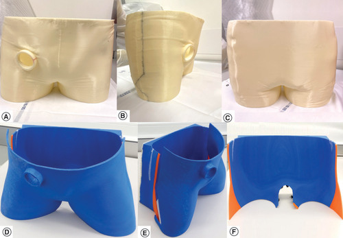
Using a dedicated table, made of non scattering organic polymer compatible with the surface scanner wavelength, volunteers were placed in a supine position reproducing standard positioning for pelvic EBRT treatments. Knee and ankle support were available per need. US reference images were acquired in this position using a conventional US imaging probe (CHISON Medical Technologies, Sonobook 6, P2-V probe, Jiangsu, China) maintained still by an articulated arm under the supervision of an expert radiologist. Abdominal pulsed color Doppler imaging focusing on the right iliac artery was used as internal organ landmark. The pelvic region and the US imaging probe were modeled with the help of images acquired with a portable metrology grade surface-scanner (HandySCAN™ 300, Creaform, QC, Canada). Its main acquisition parameters are following: optical resolution = 0.025 mm; mesh resolution = 0.1 mm; sampling rate = 205 kHz; light source = 3 lasers diodes; stand-off distance = 300 mm; depth of field = 250 mm. The resulting surface image was cleaned and extruded to a thickness of 5 mm using the accompanying software VxElements™ (Creaform, Canada). First tests of the scanner were previously reported [Citation34]. A 3D model prototype device (), bearing the information of the US probe’s angulation and position was created. An MRI-compatible and radiation-resistant acrylonitrile–butadiene–styrene (ABS) material was used to print the first device using an A2v4 printer (3NTR, Oleggio, Italy).
(A–C) Immobilization device for the first volunteer. (D–F) Immobilization device for the second volunteer. (A & D) Front view. (B & E) Lateral view. (C & F) Backside view.
To assess the quality of all 3D-printed devices, the printed objects were scanned using the same high-accuracy HandySCAN surface scanner used for the model creation. These scans where then semi-automatically aligned and compared with the models used to create the devices using the scanner’s accompanying software VxElements to calculate and report a surface deviation distribution. A computed tomography (CT) [Citation35] scan (Philips Big Bore, Utrecht, The Netherlands) of the empty device was acquired with a 1 mm slice thickness and the external device surface was delineated. A dummy radiotherapy (RT) plan was created from this CT scan data and used together with the device contour in order to create a dummy reference surface for the optical surface monitoring (OSM) system (AlignRT™, VisionRT, London, UK). This dummy surface was not used for testing on the volunteer but only to allow opening the AlignRT software in the LINAC treatment room (Truebeam, Varian Medical systems, CA, USA). However, as also foreseen for final clinical application, the CT scan allows to check the internal quality and homogeneity of the device by visual inspection and by looking at the Hounsfield units (HU) properties of the device’s contour. This is drawn automatically by selecting a HU window level. A minimum of -650 HU was chosen so that the shell thickness corresponded to its physical thickness.
Measurements procedures
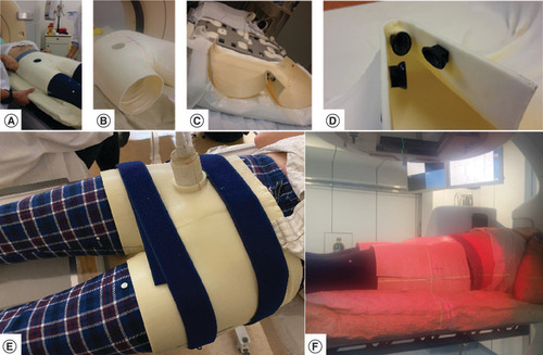
In order to attach the immobilization device to the LINAC table, a standard Vac-Lok cushion fixed onto the couch (A) was molded, using the Vac-Lok cushion position as reference frame for the position measurements. The CT image acquisition of the empty device (B) was used for the RT dummy plan. A similar immobilization system was adopted for the MRI table using a more compact cushion (C) because the Vac-Lok system was too large and collided with the MRI ring. Three MRI compatible aqueous gel markers were fixed on the bottom segment of the shell to check for movements of the volunteer with respect to the shell, and of the shell with respect to the MRI table (D). US images were acquired outside the MR room (E).
(A) Adjustment of the Vac-Lok™ receiving the inferior part of the immobilization device. (B) Inferior and superior part of the immobilization device used for the computed tomography data acquisition. (C) Inferior part of the device attached to the MR table. (D) Rigid loci for embedding MRI markers on the lower part of the device. (E) Ultrasound imaging probe attached to the device. (F) LINAC OSM measurements.
LINAC: Linear accelerator; LINAC OSM: Linear accelerator optical surface monitoring; MR: Magnetic resonance.
Moreover, an experimentation was added to evaluate the accuracy of patient positioning without an immobilization device. As there is no repositioning system for MRI in clinical routine, to show the added value of our system, a technique similar to tattooing in radiotherapy has been used. On the same volunteers as previous, two landmarks were placed on the patient’s body (right and left hip) and two landmarks on the MRI table. Then the volunteer was asked to position himself on the table. Two operators further helped him to get the position of best registration between patient landmark and MRI table landmark, direction head-feet and craniocaudal, respectively. The skin-to-table landmark alignment was visually confirmed within better than 1 mm precision. Furthermore, an MRI marker was attached to the MRI table to check for the table–patient position while imaging.
To measure the positioning reproducibility achievable with the customized 3D-printed immobilization device, an OSM system was used for three measurement sessions at the LINAC, followed by a 3 T MRI acquisition (Magnetom Prisma Fit, Siemens, Erlangen, Germany). Each measurement session (OSM or MRI), was composed of 6 or 7 repeated measurement sequences in which the volunteer was asked to position himself within the bottom shell of the device. The top part was then added. After removal of the top part of the device, an image of the volunteer’s body shape was acquired with the OSM system (F) and used as reference for measuring shifts between positioning tests.
Between each measurement the volunteer got out of the immobilization support and then repositioned himself in it. No lasers or skin marks were used to align the volunteer on the LINAC or MRI table, always positioned with the same vertical, longitudinal and lateral coordinates. Measurement sessions 2 and 3 were performed on the same day, 1 week after the first one, while the session at MRI and in the medical room was performed some weeks later.
Using the sub-millimetric positioning resolution of the AlignRT system and the LINAC couch [Citation36,Citation37], three position offsets (vertical, horizontal and longitudinal) and three rotation angles (yaw, roll and pitch) were registered for each one of the three LINAC sessions, using the first volunteer positioning of the day as a reference.
For the MRI sessions, with and without immobilization device, the position differences between the reference 3D image and the other acquisition sequences were calculated on the Eclipse™ treatment planning system (Varian medical systems, Palo Alto, CA, USA) by collecting the matrix registration parameters (translations and rotations). Using an automatic algorithm of the treatment planning system, the co-registration between images acquisitions was made on the bony anatomy. The fourth image sequence was used as reference image of the session in order to consider anatomical pelvic changes (bladder and rectal filling) potentially occurring during the approximately 40 min long acquisition (for the seven images) that might have made the volunteer uncomfortable and; therefore, less reproducible in positioning. The main parameters of the T1-weighted turbo spin echo MR sequence acquired during each image acquisition were: repetition time (TR) = 784 ms; echo time (TE) = 12 ms; bandwidth (BW) = 170 Hz/pixel; turbo spin echo factor = 3; refocusing pulse 180°; physical resolution 1.56 mm × 1.17 mm × 3 mm; GRAPPA = 2; field of view (FOV) = 300 mm; phase encoding direction HF; phase oversampling = 80%; number of signals averaged (NSA) = 2; acquisition time (TA) = 185 s; coil combination spine and body matrix (n = 30 elements). In addition, the distance between the MRI markers attached to the shell and the lower anterior corner of the sacral body S1 was measured on the sagittal plan by an expert radiologist (J Gariani).
The 3D vector of the repositioning errors was calculated for both OSM and MRI. To compare the 3D vectors length between OSM data and MRI data the Mann–Whitney test was used, with p-values <0.05 considered statistically significant.
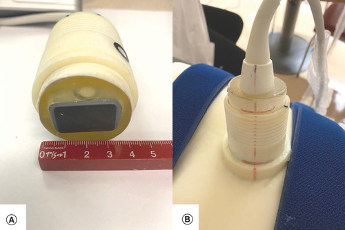
For the US imaging session, the two volunteers were installed in the same position as during the 3D-surface scan. An elastic belt was wrapped around the two-part immobilization device. The US probe was inserted in the dedicated holder of the 3D immobilization support (A & B). US images were acquired and compared with the reference images (made prior the creation of the immobilization device) using a visual depth scaling (cm) ruler present on the US images to check for positioning accuracy between images.
(A) Highlight of the ultrasound imaging probe. (B) The embedded holder.
The time required for the volunteer to find the optimal position was registered and analyzed after dichotomization in two categories (≤1 or >1 min). All volunteers had signed an informed consent by each patient in order to enroll them in the study and collect their data.
Results
The printing time of the immobilization device for the first volunteer was 65 h and the device, split in two parts, measured approximatively 35 cm × 33 cm × 12 cm (per piece), for a total weight of 1.3 kg. For the second device the printing time was 77 h, measured approximatively 51.5 cm × 35 cm × 16 cm (per piece) for a total weight of 1.7 kg. The volunteers were chosen with two different BMIs of 22 and 31 for volunteer 1 and 2, respectively, to prove that the 3D immobilization system can be adapted to different types of morphology.
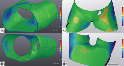
The CT scan density of the immobilization device was uniform for all volunteers, with a mean HU number of -350 (standard deviation [SD] ±125). Comparison on the VxElements platform between the original models used for 3D printing and the surface scans of the printed parts of two volunteers are illustrated in . The distribution of surface deviations is almost Gaussian, with a mean of zero for both volunteers (SD of 0.3 mm and maximum deviations of less than 0.7 mm for the first volunteer and SD of 0.5 and maximum deviations of less than 1.0 mm for the second).
(A & B) Surface mapping of the material accuracy of the 3D-printed device for the first volunteer. (C & D) Surface mapping of the material accuracy of the 3D-printed device for the second volunteer. The VxElements™ platform visualizes surface deviations between the numerical device model and the 3D-surface scan of the real object.
As measured by the OSM system at the LINAC, calculated setup errors in the vertical and lateral directions overall measurement sessions were minimal, with a median value smaller than 1 mm and a range of about 2 mm for both volunteers (). In the longitudinal direction, which corresponds to the axis along the patient body, deviations were larger with a median of 4.4 mm and a range of 18.8 mm for the first volunteer (BMI = 22). Rotation values in the three axes were small with median values inferior to 1/3 of a degree and a range of about 1°. For the second volunteer (BMI = 31), the longitudinal deviations were smaller than 0.7 mm, with a range of 1.2 mm due to a better fixation on the couch. Rotations values in the three axes were larger, with a median of almost 1° and a range of 1.5°. The increase in rotation values was potentially due to the weight loss of the volunteer between the 3D scan and the measure with the OSM system (from BMI: 31.4 to BMI: 29.8).
Table 1. Prepositioning deviations from repeated fitting sessions at the LINAC for two volunteers.
Example of repositioning results and using the device, as assessed on MRI for a volunteer are shown in and illustrated on . By using the 3D-printed device, the reproducibility based on the bony anatomy was excellent for both volunteers, with only small lateral and vertical deviations with a median value of less than 0.5 mm and a range of about 2.5 mm for the first volunteer and a median value of 0.5 mm with a range of 3.8 mm for the second. In analogy to the LINAC measurements, longitudinal deviations were the largest, with a median of 1.4 mm and a range of 8.5 mm for the first volunteer and a median of 1.4 mm and a range of 7.5 mm for the second. Rotations were small with a median value near to zero and a range of about 1° for the first volunteer and a median near 0.5° with a range of about 2° for the second.
Table 2. Prepositioning deviations of the internal bony anatomy from repeated fitting session of two volunteers as measured using MRI using the immobilization device.
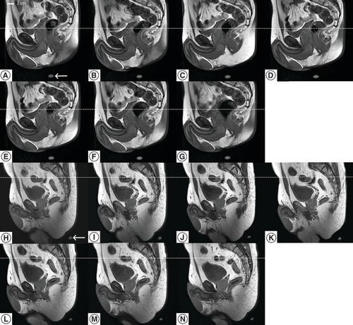
Serial MR images of the same sagittal slice after repositioning of a volunteer in the immobilization device, during 40 min period. All images shared the same DICOM coordinates. One MR marker is visible on each image (bottom). The dotted line is a visual support for the craniocaudal displacement.
DICOM: Digital imaging and communications in medicine; MR: Magnetic resonance.
When analyzing the 3D vector values obtained with the two measurement modalities (OSM and MRI), the difference between the two median values was larger for the first volunteer, 4.5 versus 1.5 mm for the OSM and MRI technique and smaller, and 0.8 versus 2.3 mm for the second volunteer.
Complimentary, on the seven MRI acquisitions the calculated mean (SD) distance between the MRI markers on the shell and the lower anterior corner of the vertebral body S4 was 210.7 (1.8) mm for the first volunteer and the calculated mean (SD) distance between the MRI markers on the shell and the lower anterior corner of the vertebral body S2 was 196.4 (1.4) mm for the second volunteer. These results confirmed that patient’s bone anatomy position was reproducible with respect to the rigid shell itself with millimeter accuracy.
Repositioning results determined on MRI for the two volunteers without immobilization device are shown in . As expected, the treatment would not be accurate, the median modulus of the computed-3D displacement vector is 4- to 6-times larger without immobilization device than with device. This condition was confirmed by the large SD of the measured distance between the MRI marker on the MR table and the lower anterior corner of the vertebral body S4 without device, 9.5 mm for the first volunteer and 6.6 mm for the second, to be compared with figures above (1.8 and 1.4 mm).
Table 3. Prepositioning deviations of the internal bony anatomy from repeated fitting session of two volunteers as measured using MRI without immobilization device.
The time needed for the two volunteers to self-align in the immobilization device and accommodate was always less than 1 min for all of the measurement sequences (n = 28).
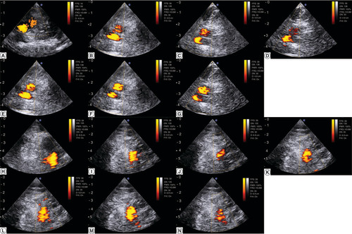
Finally, the agreement in target repositioning was high between the US reference image from the surface scanning setup and the ulterior image acquired with the US probe embedded in the customized 3D device: the right iliac vessels were in the same anatomic plane, visualized at similar depth within 2 mm precision, as illustrated on A–G for the first volunteer and H–N for the second volunteer. This is a measure of how a US HT applicator could appropriately target the region to heat up.
(A) Pulsed-color Doppler ultrasonography of the right iliac vessels the day of the surface scanning for the first volunteer. (H) Pulsed-color Doppler ultrasonography of the right iliac vessels the day of the surface scanning for the for the second volunteer. (B–G) Serial acquisition after the volunteer repositioning in the immobilization device for the first volunteer. (I–N) Serial acquisition after the volunteer repositioning in the immobilization device for the second volunteer. A scale distance is provided left side, graduated in cm.
Discussion
MRgFUS-based deep HT represents a promising technology for improving the therapeutic ratio of curative EBRT treatments [Citation18,Citation29]. In this study, with our 3D-printed immobilization pelvic device, the position of volunteers on both the LINAC and the MRI was reproducible.
Tests indicated positioning errors monitored at the LINAC by the OSM system were millimetric, with body rotations mainly within 0.5°. Of note, these results were obtained by positioning the couch always at the same spatial coordinates, with no use of lasers or marks on the immobilization device. On the other hand, as already demonstrated in the literature [Citation38], the largest positioning errors was in the longitudinal axis. By limiting rotational movements, improvements in daily reproducibility may be expected especially for LINACs equipped with a fixed flat couch that do not allow rotational corrections, like on MR-LINACS. It is worth noting that, uncorrected rotational errors may have a significant effect on organ sparing, as observed for example for the rectal V50Gy dose parameter in prostate cancer patients [Citation39].
The MRI tests showed the potential ability of the device to ensure a bony based inter fractional repositioning with millimetric accuracy () and limited longitudinal movements. In addition, by fixing the patient on the couch, improvements in reducing the intrafraction motion of the patient during the EBRT and HT sessions can be expected using such a device, even if this benefit remains to be demonstrated. On the other hand, as expected, the internal organ displacement was greater over time as observed during the 40 min MRI acquisition time (), mainly due to the bladder and rectum filling [Citation30]. Implementation in the daily clinical practice of dedicated rectal and bladder preparation protocols is expected to improve the intrafraction reproducibility of HT treatments.
The OSM measuring procedure showed larger prepositioning errors compared with the MRI results. This difference between the two measuring procedures was likely due to the error induced by the physiological breathing when using the OSM system, as previously shown by Li et al. [Citation40].
With this study the possibility of embedding an US applicator that should allow a fast and reliable positioning from one HT session to another was demonstrated, reducing patient movements and optimizing treatment time and resources. As a proof of concept and for workflow convenience, abdominal ultrasonography was used here. With respect to the US beam application for induction of deep HT in the prostate tumor bed, a transperineal acoustic window similar to commercially available transperineal 4D-ultrasound systems [Citation9] will be used; however, at higher level of applied acoustic energy. For the envisaged configuration, the direction of propagation of the acoustic beam will mainly be parallel to the longitudinal axis corresponding to a smooth attenuation profile; and therefore, the positioning error of the applicator relative to the patient pelvis in the longitudinal axis would translate into minimal effects on the thermal build up control. The requirement for positioning accuracy is significantly higher in the vertical and lateral directions corresponding to steeper thermal gradients; whereas, the beam direction needs to be controlled by electronic steering or mechanical rotation of the applicator. The reported accuracies in this study (lateral/vertical median 0.5 mm and longitudinal median 1.5 mm) are consistently compliant with the estimated needs for HIFU induced deep HT.
To the best of our knowledge, no 3D-printed immobilization pelvic devices integrating a specific US applicator holder have been described in the literature for combined EBRT and MRgFUS deep HT treatments. The complexity of creating a model that should fit a deformable region like the pelvis can represent a major challenge. The quality assurance tests performed on the device confirmed its precision despite the large size of the immobilization devices. The largest deviations were observed at the outer edges and the middle of the shell (). The thickness of the printed shell is suggested 5 mm to provide sufficient rigidity.
Our 3D-printed personalized device allowed for a fast patient self-positioning, within 1 min without the use of skin marks or lasers. Considering the patient positioning challenges in the laser-free environment of MR-LINACs and the long treatment times for adaptive treatments [Citation41], our device can be particularly interesting to improve setup times and limit the intrafraction motion of MR-guided EBRT treatments [Citation42]. On the other hand, the need of a surface scan before simulation, the required times and the cost for a 3D-printing may represent a limitation for a broad use in the clinical setting of this technology. However, in the context of a clinical study, the patient would perform the surface scan for the 3D modeling on the same day that he would have his first consultation with the radiation oncologist, where the treatment plan should be presented to him. The immobilization device would be manufactured in the following days allowing for the HT probe to be later connected and adjusted in the wanted position. The patient would further return to the hospital to perform a planning CT scan already using the 3D-printed device. The HT sessions are planned 1 h before the EBRT session. Overall, the patient should not be requested for extra visits to the hospital on the top of the standard-of-care workflow. Moreover, the required printing time would probably be alleviated in the future thanks to current research on reducing printing times and the use of several printers working together on different pieces. The high cost in the production of the device could be also alleviated when devices would be produced in larger series or, alternatively, when the department would acquire a 3D printer. Following the results of our study, immobilization of the patient and a holder for the HT transducer are necessary for the reproducibility of the treatment between each session, directly impacting the clinical outcome. Moreover, to position the patient identical in both HT and EBRT session, will make fusion of HT and EBRT planning easier. This is why our device is very interesting for this combined treatment.
The primary limitation of the study was the small sample size consisting of two volunteers with the ability to position themselves correctly in the shell. In the clinical setting, self-repositioning in the immobilization device can be difficult considering the elderly population treated for prostate cancer. Nevertheless, proper patient selection for combined EBRT-HT treatments is expected to overcome this potential limitation. If one possible disadvantage of the device may be represented by the skin ‘bolus effect’, the estimated dose increase to the skin remains minimal, especially using volumetric modulated-arcs therapies [Citation43]. Although, results of this study are preliminary and need validation in a clinical setting, they are very promising and worth exploring.
Conclusion
In conclusion, in this study the feasibility of producing a personalized 3D-printed pelvic immobilization device that could double as patient-specific US and HT transducer holder for combined EBRT and MRgFUS deep HT treatments in the pelvic region was demonstrated. The device allowed millimetric positioning accuracy and minimal angular rotations. This device may be considered a promising immobilization support able to ensure a fast patient setup and an optimal inter- and intrafractional control motion for this combined treatment as well as for modern adaptive EBRT techniques with MR-LINACs. Following future developments on the HT transducer concept, the present device will be tested in a clinical setting on prostate cancer patients.
Surface scanning and 3D printing were used to create a new type of immobilization device for patient prepositioning and probe holder for prostate radiotherapy and MRI-guided ultrasonic transperineal hyperthermia.
Optical surface monitoring at the linear accelerator (LINAC) indicated vertical, lateral and longitudinal median setup errors on average 0.1, 0.4 and 2.5 mm and corresponding differences at magnetic resonance (MR) were -0.1, 0.4 and -1.4 mm.
A conventional ultrasound-imaging probe was employed as proof of concept for intersession reproducibility of the acoustic beam geometry and imaging plane in place of the therapeutic ultrasound applicator.
This device may be considered a promising immobilization support able to ensure a fast patient setup and an optimal inter- and intrafractional control motion for this combined treatment as well as for modern adaptive external beam radiotherapy techniques with MR-LINACs.
Author contributions
Conception/design of the work: G Dipasquale, RV Salomir and T Zilli; data collection, statistics, original draft: G Dipasqua, RV Salomir, PC Guillemin, M Jaccard, J Gariani and T Zilli; review and editing the manuscript: G Dipasqua, PC Guillemin, M Jaccard, JWE Uiterwijk, O Lorton, P Tsoutsou, P-A Poletti, J Gariani, RV Salomir and T Zilli. All authors read and approved the final manuscript.
Ethical conduct of research
The authors state that they have obtained appropriate institutional review board approval (Local approval from Geneva’s CCER no: 2019-0800) and have followed the principles outlined in the Declaration of Helsinki for all human or animal experimental investigations. In addition, for investigations involving human subjects, informed consent has been obtained from the participants involved.
Acknowledgments
The authors would like to thank 3NTR (Oleggio, Italy) for their commitment and resilience during the COVID-19 period as well as P Faria, for his assistance at the LINAC.
Financial & competing interests disclosure
The study was funded by the Swiss National Science Foundation research project 320030_182366, by a STARTUP grant of the University Hospital of Geneva (2015-04) and a grant of the ‘Fondation Privée des HUG’ (project no.: QS03-34). G Dipasquale and Geneva University Hospitals have a patent pending to parts of the method used in this work (WO2020099510A2). The authors have no other relevant affiliations or financial involvement with any organization or entity with a financial interest in or financial conflict with the subject matter or materials discussed in the manuscript apart from those disclosed.
No writing assistance was utilized in the production of this manuscript.
Additional information
Funding
References
- Ssrpm . Report number 11, Revision 2014. Quality control of medical electron accelerators. ISBN 3 908 125 57 X (2014) ( Epub ahead of print).
- Carrie C , MagneN, Burban-ProvostPet al. Short-term androgen deprivation therapy combined with radiotherapy as salvage treatment after radical prostatectomy for prostate cancer (GETUG-AFU 16): a 112-month follow-up of a phase III, randomised trial. Lancet Oncol.20(12), 1740–1749 (2019).
- Achard V , PanjeCM, EngelerD, ZilliT, PutoraPM. Localized and locally advanced prostate cancer: treatment options. Oncology. 99(7), 413–421 (2021).
- Tendulkar RD , AgrawalS, GaoTet al. Contemporary update of a multi-institutional predictive nomogram for salvage radiotherapy after radical prostatectomy. J. Clin. Oncol.34(30), 3648–3654 (2016).
- Dal Pra A , PanjeC, ZilliTet al. Salvage radiotherapy for macroscopic local recurrences after radical prostatectomy: a national survey on patterns of practice. Strahlenther. Onkol.194(1), 9–16 (2018).
- Zilli T , JorcanoS, PeguretNet al. Results of dose-adapted salvage radiotherapy after radical prostatectomy based on an endorectal MRI target definition model. Am. J. Clin. Oncol.40(2), 194–199 (2017).
- Zilli T , JorcanoS, PeguretNet al. Dose-adapted salvage radiotherapy after radical prostatectomy based on an erMRI target definition model: toxicity analysis. Acta Oncol.53(1), 96–102 (2014).
- Picardi C , PerretI, MiralbellR, ZilliT. Hypofractionated radiotherapy for prostate cancer in the postoperative setting: what is the evidence so far. Cancer Treat. Rev.62, 91–96 (2018).
- Richter A , ExnerF, WeickSet al. Evaluation of intrafraction prostate motion tracking using the Clarity Autoscan system for safety margin validation. Z. Med. Phys.30(2), 135–141 (2020).
- Dewhirst MW , VujaskovicZ, JonesE, ThrallD. Re-setting the biologic rationale for thermal therapy. Int. J. Hyperthermia21(8), 779–790 (2005).
- Datta NR , PuricE, KlingbielD, GomezS, BodisS. Hyperthermia and radiation therapy in locoregional recurrent breast cancers: a systematic review and meta-analysis. Int. J. Radiat. Oncol. Biol. Phys.94(5), 1073–1087 (2016).
- Datta NR , RogersS, OrdonezSG, PuricE, BodisS. Hyperthermia and radiotherapy in the management of head and neck cancers: a systematic review and meta-analysis. Int. J. Hyperthermia32(1), 31–40 (2016).
- Datta NR , StutzE, GomezS, BodisS. Efficacy and safety evaluation of the various therapeutic options in locally advanced cervix cancer: a systematic review and network meta-analysis of randomized clinical trials. Int. J. Radiat. Oncol. Biol. Phys.103(2), 411–437 (2019).
- Crezee J , Van LeeuwenCM, OeiALet al. Biological modelling of the radiation dose escalation effect of regional hyperthermia in cervical cancer. Radiat. Oncol.11, 14 (2016).
- Beck M , GhadjarP, MehrhofFet al. Salvage-radiation therapy and regional hyperthermia for biochemically recurrent prostate cancer after radical prostatectomy (results of the planned interim analysis). Cancers (Basel)13(5), 1133 (2021).
- Kok HP , CrezeeJ, FrankenNA, StalpersLJ, BarendsenGW, BelA. Quantifying the combined effect of radiation therapy and hyperthermia in terms of equivalent dose distributions. Int. J. Radiat. Oncol. Biol. Phys.88(3), 739–745 (2014).
- Guillemin PC , GuiL, LortonOet al. Mild hyperthermia by MR-guided focused ultrasound in an ex vivo model of osteolytic bone tumour: optimization of the spatio–temporal control of the delivered temperature. J. Transl. Med.17(1), 350 (2019).
- Zhu L , LamD, PaciaCPet al. Characterization of magnetic resonance-guided high-intensity focused ultrasound (MRgHIFU)-induced large-volume hyperthermia in deep and superficial targets in a porcine model. Int. J. Hyperthermia37(1), 1159–1173 (2020).
- Baust JM , RabinY, PolascikTJet al. Defeating cancers’ adaptive defensive strategies using thermal therapies: examining cancer’s therapeutic resistance, ablative, and computational modeling strategies as a means for improving therapeutic outcome. Technol. Cancer Res. Treat.17, 1533033818762207 (2018).
- Jolesz FA . MRI-guided focused ultrasound surgery. Annu. Rev. Med.60, 417–430 (2009).
- Melodelima D , SalomirR, MougenotCet al. Intraluminal ultrasound applicator compatible with magnetic resonance imaging “real-time” temperature mapping for the treatment of oesophageal tumours: an ex vivo study. Med. Phys.31(2), 236–244 (2004).
- Moonen CT , QuessonB, SalomirRet al. Thermal therapies in interventional MR imaging. Focused ultrasound. Neuroimaging Clin. N. Am.11(4), 737–747 (2001).
- Zhou YF . High intensity focused ultrasound in clinical tumor ablation. World J. Clin. Oncol.2(1), 8–27 (2011).
- Marien A , GillI, UkimuraO, BetrouniN, VillersA. Target ablation--image-guided therapy in prostate cancer. Urol. Oncol.32(6), 912–923 (2014).
- Rueff LE , RamanSS. Clinical and technical aspects of MR-guided high intensity focused ultrasound for treatment of symptomatic uterine fibroids. Semin. Intervent. Radiol.30(4), 347–353 (2013).
- Ellis S , RiekeV, KohiM, WestphalenAC. Clinical applications for magnetic resonance guided high intensity focused ultrasound (MRgHIFU): present and future. J. Med. Imaging Radiat. Oncol.57(4), 391–399 (2013).
- Guilhon E , QuessonB, Moraud-GaudryFet al. Image-guided control of transgene expression based on local hyperthermia. Mol. Imaging2(1), 11–17 (2003).
- Zhu L , HuangY, LamDet al. Targetability of cervical cancer by magnetic resonance-guided high-intensity focused ultrasound (MRgHIFU)-mediated hyperthermia (HT) for patients receiving radiation therapy. Int. J. Hyperthermia38(1), 498–510 (2021).
- Zhu L , PartanenA, TalcottMRet al. Feasibility and safety assessment of magnetic resonance-guided high-intensity focused ultrasound (MRgHIFU)-mediated mild hyperthermia in pelvic targets evaluated using an in vivo porcine model. Int. J. Hyperthermia36(1), 1147–1159 (2019).
- Ghadjar P , FiorinoC, MunckAf Rosenschold P, PinkawaM, ZilliT, VanDer Heide UA. ESTRO ACROP consensus guideline on the use of image guided radiation therapy for localized prostate cancer. Radiother. Oncol.141, 5–13 (2019).
- Moser T , CreedM, WalkerR, MeierG. Radiotherapy tattoos: women’s skin as a carrier of personal memory – what do we cause by tattooing our patients? Breast J.26(2), 316–318 (2020).
- Sun J , PichlerP, DowlingJet al. MR simulation for prostate radiation therapy: effect of coil mounting position on image quality. Br. J. Radiol.87(1042), 20140325 (2014).
- Feddersen TV , Hernandez-TamamesJA, FranckenaM, Van RhoonGC, PaulidesMM. Clinical performance and future potential of magnetic resonance thermometry in hyperthermia. Cancers (Basel)13(1), 33 (2020).
- Dipasquale G , PoirierA, SprungerY, UiterwijkJWE, MiralbellR. Improving 3D-printing of megavoltage X-rays radiotherapy bolus with surface-scanner. Radiat. Oncol.13(1), 203 (2018).
- Fahimian B , YuV, HorstK, XingL, HristovD. Trajectory modulated prone breast irradiation: a LINAC-based technique combining intensity modulated delivery and motion of the couch. Radiother. Oncol.109(3), 475–481 (2013).
- Schmidhalter D , FixMK, WyssMet al. Evaluation of a new six degrees of freedom couch for radiation therapy. Med. Phys.40(11), 111710 (2013).
- Schoffel PJ , HarmsW, Sroka-PerezG, SchlegelW, KargerCP. Accuracy of a commercial optical 3D-surface imaging system for realignment of patients for radiotherapy of the thorax. Phys. Med. Biol.52(13), 3949–3963 (2007).
- Bartoncini S , FiandraC, RuoRedda MG, AllisS, MunozF, RicardiU. Target registration errors with surface imaging system in conformal radiotherapy for prostate cancer: study on 19 patients. Radiol. Med.117(8), 1419–1428 (2012).
- Chiesa S , PlacidiL, AzarioLet al. Adaptive optimization by 6 DOF robotic couch in prostate volumetric IMRT treatment: rototranslational shift and dosimetric consequences. J. Appl. Clin. Med. Phys.16(5), 35–45 (2015).
- Li W , JiangZ, ChuK, JinJ, GeY, CaiJ. A noninvasive method to reduce radiotherapy positioning error caused by respiration for patients with abdominal or pelvic cancers. Technol. Cancer Res. Treat.18, 1533033819825865 (2019).
- Mcpartlin AJ , LiXA, KershawLEet al. MRI-guided prostate adaptive radiotherapy – a systematic review. Radiother. Oncol.119(3), 371–380 (2016).
- Grimwood A , McnairHA, O’sheaTPet al. In vivo validation of Elekta’s clarity autoscan for ultrasound-based intrafraction motion estimation of the prostate during radiation therapy. Int. J. Radiat. Oncol. Biol. Phys.102(4), 912–921 (2018).
- Wang L , CmelakAJ, DingGX. A simple technique to improve calculated skin dose accuracy in a commercial treatment planning system. J. Appl. Clin. Med. Phys.19(2), 191–197 (2018).