Abstract
Femoral head resurfacing is re-emerging as a surgical option for younger patients who are not yet candidates for total hip replacement. However, this procedure is more difficult than total hip replacement, and the mechanical jigs typically used to align the implant produce significant variability in implant placement and take a significant amount of time to position properly. We propose that a computer-assisted surgical (CAS) technique could reduce implant variability with little or no increase in operative time. We describe a new CAS technique for this procedure and demonstrate in a cadaver study of five paired femurs that the CAS technique in the hands of a novice surgeon markedly reduced the varus/valgus variability of the implant relative to the pre-operative plan (2° standard deviation for CAS versus 5° for a mechanical jig operated by an expert surgeon). We also show that the mechanical jig resulted in significantly retroverted implant placement. There was no significant difference in operative time between the two techniques.
Introduction
Although total hip arthroplasty is quite predictable and durable in older patients, the results in young, active patients have been less predictable, especially if older reconstructive techniques and bone cement were used; these tend to produce high rates of articular bearing wear and component loosening Citation[1–5]. Although these outcomes have been much improved by the introduction of cementless fixation and contemporary bearing surfaces, concern remains regarding the long-term outlook in young, active patients over the remainder of their life span, which may exceed 50 years.
In an effort to ‘gain time’ and delay entry to the medullary canal, there has been renewed enthusiasm for the concept of femoral head resurfacing for the young patient afflicted with osteoarthritis or avascular necrosis of the femoral head Citation[6–8]. Proponents of the technique suggest that not only does it preserve femoral head bone stock, but, in comparison to total hip arthroplasty, it also more closely approximates normal hip kinematics, joint stability, and proprioception, while minimizing the potential for post-operative leg-length discrepancy and stress shielding of the proximal femur Citation[7], Citation[9], Citation[10]. Furthermore, it has been suggested that, due to extremely low rates of articular bearing wear in metal-on-metal hip resurfacing arthroplasty, this technique may permit the patient to return to a greater level of activity and sport than other reconstructive options Citation[7]. Indeed, even though younger patients place high activity demands on these implants, early clinical results are very good, with multiple authors reporting 2- to 5-years survivorship of 94–98% Citation[6], Citation[8], Citation[9].
However, despite the attractive early clinical results and success, there continues to be a number of complications and potential concerns with the surgical technique that are unique to this procedure. In comparison to total hip arthroplasty, the surgical technique is more complex and demanding for the surgeon. To adequately visualize the femoral head and neck, the surgeon must use a wide exposure of the hip. The instrumentation for femoral head preparation is based entirely on the placement of a femoral head and neck guide pin. Pin placement is a time-consuming process in the operating room (OR) and, despite the surgeon's efforts to center the pin using intra-operative guides and calipers, the surgical technique can be unreliable Citation[11] and may result in sub-optimal component placement or notching (unplanned cortical bone violation) of the femoral neck. Femoral neck notching and varus placement of the resurfacing component have been demonstrated to increase the risk of post-operative femoral neck fracture Citation[8], Citation[10]. In addition, malposition of the guide pin may result in oversizing the femoral head component, which may then necessitate excessive removal of acetabular bone stock for acetabular component placement. Malposition of the femoral component may also compromise the hip's range of motion and patient satisfaction with the procedure.
Failure to pay attention to these nuances may explain some of the unique complications of resurfacing arthroplasty, which include post-operative femoral neck fracture requiring revision surgery, implant loosening, and avascular necrosis of the femoral head, which may result in symptoms of pain or femoral head collapse and loosening of the resurfacing component Citation[7]. These highly technical aspects of the procedure are evident in the improvement in accuracy of component placement and the reductions in the rates of femoral neck notching, fracture, and revision with increasing numbers of resurfacing procedures performed Citation[12], Citation[13].
Methods for improving femoral head/neck pin placement and instrumentation of the femoral head have largely involved pre-operative planning, templating, and radiographic calculations. In addition, a number of jigs, calipers, and femoral neck gauges have been developed to help guide the surgeon's pin placement intra-operatively.
Despite the refinement of these methods, there continues to be a tremendous variability in final guide-pin placement and femoral component placement Citation[11] among both novice and experienced hip surgeons. We propose that contemporary methods of computer-assisted navigation could be used to optimally prepare the femoral head and place the guide pin and component. If successful in this application, computer-assisted femoral head resurfacing may result in improved outcomes by decreasing complication rates (reduced femoral neck notching/fracture rate and avascular necrosis), improving component placement and hip range of motion/kinematics, decreasing OR time, allowing surgeons to use the smallest size femoral head component safely possible for each patient (and thereby minimize unnecessary acetabular bone removal for acetabular instrumentation), and creating opportunities to perform resurfacing through less invasive surgical incisions. Since this study began, Hess and McMinn have independently developed a CAS system for this application in collaboration with BrainLAB (http://www.dreifaltigkeits-hospital.de/abt/first.html), but this does not appear to consider ante/retroversion directly and requires intraoperative fluoroscopic imaging Citation[17]. Other systems have also been proposed to address this problem, ranging from digitizing arms to CT Citation[14–16],Citation[18–20], but the potential gains in accuracy from computer assistance have not been fully characterized.
The overall purpose of this study, therefore, was to evaluate a new CAS-based process that we have developed for femoral head resurfacing. Our specific research questions were as follows: (1) Does our method yield less varus/valgus angulation relative to the pre-operative plan than a commonly used mechanical method (the Durom system made by Zimmer, Inc., Winterthur, Switzerland)? (2) What is the relative angular variability of the methods? (3) How much angular variability results from driving the pin? and (4) Is there any significant difference in the time taken by the two methods?
Methods
CAS system description
We designed a CAS system to transfer pre-operative plans formulated on an anteroposterior (AP) radiograph and a mediolateral (ML) radiograph, if available, to the OR. Intra-operatively, the surgeon uses optical tracking of the femur and several tools: a registration tool, a caliper tool, a digitizing probe, and a drill guide. The primary steps in the procedure are as follows:
(a) Preoperative planning (): On the AP radiograph, the surgeon draws a line across the superior aspects of the femoral head and the greater trochanter (GT), and another line along the desired implant axis through the femoral neck, then inputs the angle between these two lines into the CAS system. If an ML radiograph is available, the surgeon draws the best line possible through the most posterior points of the femoral head, GT, and lesser trochanter (LT), and draws another line along the desired implant axis, then inputs the angle between these two lines (positive angles for anteversion of the implant). If an ML radiograph is not available, or the angle of view is such that the most posterior points of the femoral head, GT, and LT are substantially out of line, this step can be omitted and the CAS system will use a default value of 5° anteversion.
(b) Registration tool (): The registration tool has two rigid planar surfaces normal to each other and reports these planes to the CAS system. The surgeon positions the registration tool on the femur such that the first surface contacts the superior aspect of the femoral head and GT, whereas the second surface contacts the most posterior aspects of the femoral head, GT, and LT. When in contact at these five points, the tool is aligned with the two reference lines drawn on the plan. The planned implant axis orientation may then be calculated using the angles input from the pre-operative plan. The position of this axis is determined and its anteversion angle is refined in the subsequent steps.
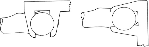
(c) Caliper tool (): The caliper tool reports the midline between the caliper faces to the CAS system. The surgeon closes the caliper across the superior and inferior aspects of the narrowest section of the femoral neck (as viewed in the frontal plane), recording an approximately AP line through the middle of the femoral neck at the narrowest point. The surgeon then closes the caliper on the anterior and posterior aspects of the femoral neck at five locations spread out as far as possible. This records five approximately proximal–distal (PD) lines passing through the middle of the femoral neck bone stock. These lines are projected into a plane normal to the planned implant axis, and the average of the intersections between each of the five projected PD lines and the AP line is taken as the neck center. The final implant axis is then calculated as the best-fitting line through the intersection points of the five PD lines and a plane normal to the plane through the most posterior aspects of the femoral head, GT, and LT, passing through the neck center, and rotated to the varus–valgus angle of the planned implant axis. The implant axis is thereby positioned and its anteversion angle is refined to follow the middle of the femoral neck bone stock as determined directly from the bone by the caliper tool.
(d) Digitizing probe: As an option, the surgeon may then use the conventional point digitizing probe to record potential notching points on the femoral neck. The CAS system calculates the minimum reamer size that will encircle these points when passed along the calculated implant axis. The surgeon may then input a smaller reamer size and the CAS system will calculate (if possible) the translation of the implant axis required for the smaller reamer to pass the digitized notching points. This option allows the surgeon to accept a translation of the implant axis slightly off the middle of the femoral neck in order to use a smaller implant without notching.
(e) Drill guide: A hand-held drill guide is tracked by the CAS system, which displays its position relative to the calculated implant axis.
Figure 1. Preoperative planning of varus–valgus angle (left) on AP radiograph and anteversion angle (right) on ML ratiograph.
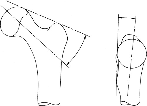
Figure 2. Registration tool position on femur.
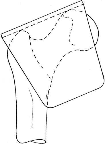
Figure 3. Caliper tool position for AP line (left) and PD lines (right).
Study design
After verifying the basic functionality of our system with artificial bone models, we performed a cadaveric study using five pairs of proximal femurs (plus one pilot specimen) draped to simulate the OR situation (). We mounted holding pins to each bone, so that it could be repeatably placed in a jig, and took both AP and ML radiographs at 90° to one another. An expert surgeon, who regularly uses the Zimmer Durom with its mechanically based alignment system, then used the radiographs to plan the desired implant axis. Next, each bone was registered with our CAS system. On one of each pair of femurs, a novice surgeon used the CAS system to calculate a guide-pin axis at the planned angles through the center of the narrowest point of the femoral neck. The calculated target axis for the drill guide was recorded, and the final pin position measured after the novice surgeon drove the pin. The pin was then moved out of the way and the expert set the Durom jig according to established practice, but did not drive the pin, and the targeted pin axis was recorded. On the contralateral limb, the expert surgeon set the Durom jig and drove the pin. The Durom guide setting and the final pin position were measured. Following the experimental session, we remounted the bones in the X-ray jig and retook AP and ML radiographs of each specimen to permit evaluation of the actual pin placement ().
Figure 4. Femoral head as draped for the experiment. A rigid body with an optical reference frame is attached to the femur.
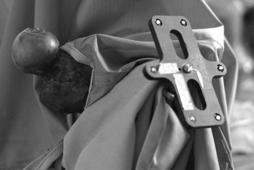
Figure 5. Post-operative X-rays used to assess pin placement relative to initial surgical goals.
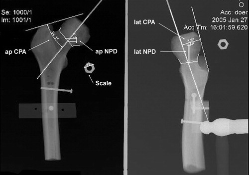
The entire experiment was videorecorded. For each femur, we measured the time, in minutes, of the decision-making process. In the Durom procedure, we started timing at the beginning of the Durom jig insertion and stopped when the surgeon started the final pin placement (pin insertion with Durom). Thus, the time for the Durom process included positioning and adjusting the jig and checking the position with the normal ancillary tools until the surgeon was sufficiently satisfied to proceed with drilling the pin. In the CAS procedure, we started timing when the registration began and stopped when the surgeon started to place the final pin. Thus, the time for the CAS process included intra-operative registration, calculation of the ideal trajectory, and navigation of the pin insertion until the surgeon was sufficiently satisfied to drill the pin. On the CAS-guided trials, we also timed the simulated Durom setup.
Differences between the mean values for the two techniques were computed using Student's t-test, whereas differences in estimated standard deviations were computed using the F-test. All differences were evaluated for significance based on a p-value of 0.05.
Results
The results are shown in . Regardless of the method used, all driven pins looked reasonably well placed (in contrast to clinical experience with a different mechanical jig system Citation[11]). The standard deviations from the pre-operative plan in varus/valgus were significantly lower for the CAS method (2.2°) than for the Durom method (5.5°), although biases in all cases were < 3.3° and not significantly different from zero. The Durom/expert axis settings were significantly retroverted relative to the CAS axis (average = 8°). The varus–valgus differences between the methods had low bias and were generally within 4° of one another, but differences ranged from 8° in valgus to 6.2° in varus. Translational differences were small at the neck center, typically approximately 2 mm.
Figure 6. Results of the experiment. Top left: varus/valgus and retro/anteversion position of the driven pin on post-operative X-ray relative to the planned line (• = Durom, ○ = CAS), along with the difference between the targeted pin axes before driving (▵ = Durom–CAS). Top right: difference between the positions of the targeted pin axes at the level of the femoral neck centre (▵ = Durom–CAS). Bottom left: variability in the final pin angle relative to the targeted pin angle due to the driving process. Bottom right: time required to aim the guide before driving the pin. The thick bars represent the standard deviation of the sample, and the thin bars represent the maximum or minimum values.
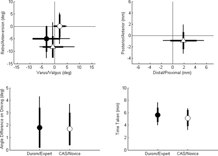
The pin-driving accuracy was similar for both methods and was small: typical errors were < 2°.
The CAS technique took slightly less time than the Durom method, although this difference was not statistically significant ().
Table I. Completion times for targeting procedure for CAS and Durom techniques.
Discussion
Our research questions related to how well the proposed CAS technique would perform relative to the existing mechanical jig system supplied by the makers of resurfacing implants such as the Zimmer Durom system. In particular, we were interested in assessing whether our approach would produce less varus/valgus angulation relative to the pre-operative plan, if the variability associated with the two methods would be lower with the CAS approach, and if the CAS approach would take longer. Furthermore, we wondered how much of the total variation between the surgical plan and the final placement could be attributed to errors in driving the pin rather than in setting up the target axis.
Post-operative X-rays showed that a novice using our proposed CAS approach had a standard deviation in varus/valgus placement relative to the planned line that was considerably less than that achieved by an expert using the Centerpulse Durom mechanical jigs. The variability in driving the pins, once targeted, was comparable for the two approaches (∼2°), and because this was on the order of the total variability for the CAS approach, the CAS registration process must be at least this accurate, and probably somewhat more so.
The two techniques did produce different results from one another, particularly in retroversion, where the mechanical jig approach was biased ∼8° relative to the CAS system, but there was no significant difference between the two in the mean varus/valgus placement, despite the difference in variance. As the CAS system produced a lower error relative to the pre-operative plan, this large difference suggests that the manual technique can introduce large errors into the ante/retroversion placement of the implant. As for the question of the time needed for a CAS procedure, our results produced no significant difference, with the CAS process actually taking less time, on average, than the manual process, even though the surgeon performing the CAS process was a resident and the one performing the manual process was an expert. This is important, because CAS procedures are more likely to be accepted if they do not increase the time needed for a procedure.
The decreased variance relative to the pre-operative plan for the novice surgeon working with the CAS method is important, because an earlier pilot study had shown that the novice surgeon who performed this study had significantly greater variability with the Durom system than the expert reported here, so the benefits of using computer assistance would likely be even more pronounced for a surgeon new to the procedure.
The Durom setup times for the expert in the live OR have been much more variable than those reported here, so these times are probably an underestimate of the true time required in the OR. The cadaveric femurs used in this study were devoid of soft tissue and muscle, and we therefore believe that the instrumentation time and accuracy of the expert surgeon may represent a ‘best case’ scenario. We suspect that there will be less variability with the CAS system, because the process will be similar in both settings.
Due to the cost of acquiring cadaveric specimens, only five pairs of femurs were used in the present study, so it would be helpful to repeat it with larger numbers. However, even with this small number of femurs, we were able to obtain some statistically significant results, so some of the effects are reasonably large.
Finally, although we controlled the positioning of the specimens to improve repeatability in taking the X-rays, these assessments are not particularly accurate, nor is a direct correspondence between the pre-operative plan and the final achieved position necessarily ideal, because the surgeon needs to be free to optimize the final implant placement to avoid notching and to minimize the size of the femoral head component in order to minimize the amount of acetabular resection required. Interestingly, Muller et al. Citation[21] recently proposed three automated methods of identifying the desired neck axis and found that in most cases manual adjustment was still necessary. The optimal varus/valgus and ante/retroversion angles have not been defined from a biomechanical standpoint, so the placement goal of the procedure is not yet well defined. We have therefore begun a study to assess the effect of varus/valgus alignment of the femoral implant on the static strength of the resurfaced femur in the presence of minor notching.
In conclusion, we have developed a CAS method for femoral head resurfacing which appears to allow a novice surgeon to implement a pre-operative plan with significantly less variability in angulation (particularly in varus/valgus) than an expert working with the Durom system, while taking a comparable amount of time.
Acknowledgment
We thank Zimmer, Inc., for providing support for this study through its Research Initiation Grant program.
References
- Duffy GP, Prpa B, Rowland CM, Berry DJ. Primary uncemented Harris–Galante acetabular components in patients 50 years old or younger: results at 10 to 12 years. Clin Orthop Relat Res 2004, 427: 157–161
- Callaghan JJ, O'Rourke MR, Saleh KJ. Why knees fail: lessons learned. J Arthroplasty 2004; 19(4 Suppl. 1)31–34
- Chandler HP, Reineck FT, Wixson RL, McCarthy JC. Total hip replacement in patients younger than thirty years old. A five-year follow-up study. J Bone Joint Surg Am 1981; 63(9)1426–1434
- Dorr LD. Comparison of primary total hip replacements performed with a standard incision or a mini-incision. J Bone Joint Surg Am 2005; 87-A(3)675
- Joshi AB, Porter ML, Trail IA, Hunt LP, Murphy JC, Hardinge K. Long-term results of Charnley low-friction arthroplasty in young patients. J Bone Joint Surg Br 1993; 75(4)616–623
- Amstutz HC, Beaule PE, Dorey FJ, Le Duff MJ, Campbell PA, Gruen TA. Metal-on-metal hybrid surface arthroplasty: two to six-year follow-up study. J Bone Joint Surg Am 2004; 86-A(1)28–39
- Beaule PE, Amstutz HC, Le Duff M, Dorey F. Surface arthroplasty for osteonecrosis of the hip: hemiresurfacing versus metal-on-metal hybrid resurfacing. J Arthroplasty 2004; 19(8 Suppl. 3)54–58
- Daniel J, Pynsent PB, McMinn DJ. Metal-on-metal resurfacing of the hip in patients under the age of 55 years with osteoarthritis. J Bone Joint Surg Br 2004; 86(2)177–184
- Treacy RB, McBryde CW, Pynsent PB. Birmingham hip resurfacing arthroplasty. A minimum follow-up of five years. J Bone Joint Surg Br 2005; 87(2)167–170
- McMinn D, Treacy R, Lin K, Pynsent P. Metal on metal surface replacement of the hip. Experience of the McMinn prothesis. Clin Orthop Relat Res 1996, 329 Suppl.: S89–S98
- Shekhman M, Masri BA, Greidanus NV, Garbuz DS, Duncan CP, Anglin C, Hodgson AJ, Inkpen KB. Variability of femoral positioning in hip resurfacing arthroplasty. Presentation at 51st Annual Meeting of the Orthopaedic Research Society, Washington, DC, February, 2005
- Mont MA, Rajadhyaksha AD, Hungerford DS. Outcomes of limited femoral resurfacing arthroplasty compared with total hip arthroplasty for osteonecrosis of the femoral head. J Arthroplasty 2001; 16(8 Suppl. 1)134–139
- Mont M, Bezweda H, Thomas C, Etienne G. The results of metal on metal resurfacing hip arthroplasty: learning curve stratification of results. Presentation at American Academy of Orthopaedic Surgeons, Washington, DC, February, 2005
- Sugano N, Nishii T, Kahahodo K, Sasama T, Sato Y, Tamura S, Sakai KT, Haraguchi K, Nishihara S, Ozono K, Yodenobu K, Yoshikawa H, Ochi T (2000) Combined acetabular and femoral navigation for resurfacing total hip arthroplasty. Computer Assisted Radiology and Surgery. Proceedings of the 14th International Congress and Exhibition (CARS 2000), San Francisco, CA, 28 June–1 July, 2000, HU Lemke, MW Vannier, K Inamura, AG Farman, K Doi. Elsevier, Amsterdam, 226–230
- Zambelli PY, Brégand CH, Dewarrat ST, Marti GS, Baur CH, Leyvarz PF (2003) Planning and navigation solution in resurfacing hip surgery—A way to reduce the surgical approach. Proceedings of the 3rd Annual Meeting of CAOS-International, MarbellaSpain, June, 2003. Darmstadt, Steinkopff
- Wacek G, Boyle D (2003) Techniques of computer-assisted surgery applied to metal on metal hip resurfacing procedures. Computer assisted radiology and surgery. Proceedings of the 17th International Congress and Exhibition (CARS 2003), LondonUK, June, 2003, HU Lemke, MW Vannier, K Inamura, AG Farman, KJ Doi, JHC Reiber. Elsevier, Amsterdam, 1329
- Hess T, Gampe T, Köttgen, Szawlowski B. Intraoperative navigation for hip resurfacing: methods and first results [In German]. Der Orthopäde 2004; 33(10)1183–1193
- Barrett ARW, Cobb JP, Jalopec M, Harris SJ, Rodriguez y Baena FM, Davies BL. The Tubes™ system for minimally invasive computer-assisted hip resurfacing surgery. Presentation at 5th Annual Meeting of the International Society for Computer Assisted Orthopedic Surgery (CAOS-International), HelsinkiFinland, June, 2005
- Harris SJ, Barrett ARW, Jakopec M, Dandachli W, Cobb JP, Davies BL. Computer assisted planning for hip resurfacing replacement surgery. Presentation at 5th Annual Meeting of the International Society for Computer Assisted Orthopedic Surgery (CAOS-International), HelsinkiFinland, June, 2005
- Long WJ, Rudan J, Ellis RE. Computer aided hip resurfacing arthroplasty. Presentation at 5th Annual Meeting of the International Society for Computer Assisted Orthopedic Surgery (CAOS-International), HelsinkiFinland, June, 2005
- Muller H, Bracke B, Dick R. Automatic detection of femoral neck axes for hip resurfacing surgeries. Presentation at 5th Annual Meeting of the International Society for Computer Assisted Orthopedic Surgery (CAOS-International), HelsinkiFinland, June, 2005