Abstract
Current techniques for total knee arthroplasty have certain drawbacks, including violation of the intramedullary canals and limited accuracy. The aim of this research was to develop and validate the accuracy of a new computer-assisted preoperative planning concept for the creation of patient-specific navigational templates to replace conventional instruments. Volumetric computerized tomography (CT) scanning was performed on 30 cadaveric knees, and a three-dimensional reconstruction model of each knee was generated from the scan data. Using a reverse-engineering technique, optimal lower-limb alignment and rotational alignment were determined. A navigational template was also designed with a surface that matched the distal femur and proximal tibia. This template, with its corresponding femur and tibia, was manufactured using a rapid-prototyping technique and tested for violations. The navigational template was then used intraoperatively to assist with an arthroplasty in each of the 30 cadaveric knees. Following surgery, the positions of the prostheses were evaluated with X-rays and CT scans. The method showed a high degree of accuracy and reproducibility. In all cases, placing the template manually on the lamina of the femur and tibia was relatively easy. Twenty-eight prostheses were considered to be positioned entirely accurately, whereas two prostheses were considered to have a 1–2° malpositioning. This study thus introduces a novel navigational template for total knee arthroplasty. Preliminary cadaveric trials have demonstrated that this design can improve the accuracy of osteotomy in the surgical procedure.
Introduction
Correct alignment of the prosthesis is very important to avoiding complications and maximizing knee function following total knee arthroplasty (TKA). Component malpositioning may lead to poor patellar tracking, polyethylene wear, and dislocation and aseptic loosening of the prosthesis Citation[1–5].
Traditionally, intramedullary and extramedullary alignment techniques are used to obtain neutral alignment during TKA Citation[6]. Unfortunately, the ability to determine the lower limb and rotational alignments accurately, both intraoperatively and on cadaveric knees, has been poor Citation[7–9]. Although various mechanical alignment guides have been designed to improve alignment accuracy in TKA, the conventional implantation technique fails in up to 30% of cases when restoring a mechanical limb axis within a range of ±3° of varus and valgus Citation[3], Citation[10]. Stulberg et al. reported that fundamental limitations exist in conventional mechanical alignment guide systems. A high degree of accuracy cannot be expected using conventional techniques for alignment by palpating anatomical landmarks Citation[11]. In addition, conventional techniques generally penetrate the intramedullary canals, increasing the risk of infection and fat embolism. Thus, achieving correct placement of the prosthesis using traditional instrumentation remains questionable.
To improve the prosthesis component alignment, image-based and image-free computer navigation systems have been introduced in TKA, and have proven to be of great value in improving the longitudinal alignment of the limb compared to results with traditional alignment techniques Citation[12–14]. However, the primary shortcomings of these navigation systems are their high cost and complexity. In addition, navigation systems require registration of bony landmarks identified on the basis of the surgeon's perception and experience. These landmarks are also relatively ambiguous and subject to errors, and may require the use of additional instruments and the insertion of tracking pins. Potential errors for misalignment may result from the bone anatomy, visual miscalculation by the surgeon, and general technical limitations Citation[15–17].
Taking these various difficulties into consideration, this study introduces a custom-fit navigational template for TKA which is further validated in cadaveric knee specimens. Based on this technique, the positions for osteotomy are first identified on the basis of the preoperative computerized tomography (CT)-scan model. The navigational template is then designed to enable patient-specific close contact with the posterior surface of the knee in order to provide maximum stability for cutting.
Materials and methods
Fifteen cadavers with knee osteoarthritis (eight males and seven females, aged 58–73 years) were obtained from the Department of Anatomy at Kunming University. They were checked by fluoroscopy to exclude other diseases of the knee. Of the 15 cadavers, 20 knees were found to have genu varum, 6 knees had genu valgum, and 4 knees were in a neutral position. TKAs were performed on the cadavers using a novel, patient-specific navigational template technique.
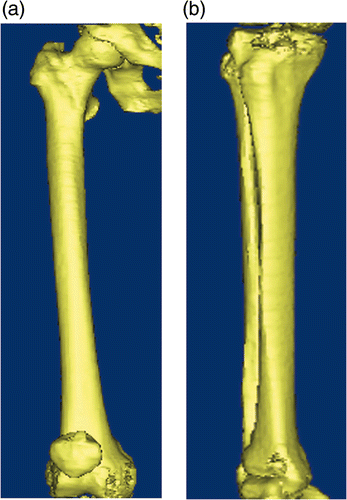
First, a spiral 3D CT scan (LightSpeed VCT; GE Healthcare, Milwaukee, WI) was performed preoperatively on the lower limb of each subject with 0.625-mm slice thickness and 0.35-mm in-plane resolution. The images were stored in DICOM format and transferred to a workstation running MIMICS 10.01 software (Materialise NV, Leuven, Belgium) to generate a 3D reconstruction model of the desired lower limb ().
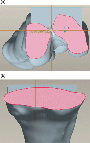
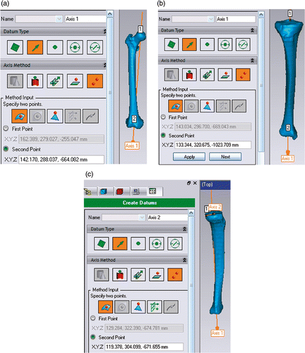
Next, the 3D model comprising the hip, knee and ankle was exported in stereolithography (STL) format to a workstation running the reverse-engineering software Geomagic Studio 10.0 (Geomagic Inc., Research Triangle Park, NC) to determine the optimal mechanical alignment. Using the Geomagic Studio software, the femoral head was considered as a sphere, and its center could then be indentified. The femoral center is located under the roof of the intercondylar notch, and the femoral mechanical axis lies between the center of the femur and the center of the femoral head (). The tibial mechanical axis is the line connecting the proximal tibial and ankle centers (), and the proximal tibial center is located at the intersection of the transcondylar axis and the anterior/posterior axis. The ankle center is the midpoint of the bimalleolar axis. The medial tibial plateau line was chosen to measure the posterior slope angle of the tibia (). A curved surface reconstruction was then performed based on the point cloud data of the STL models. Finally, the curved surface was exported in an initial graphics exchange specification (IGS) format to a workstation running the reverse-engineering software Pro/ENGINEER Wildfire 4.0 (PTC, Needham, MA) to determine the optimal rotational alignment and osteotomy position.
Figure 2. Determining the optimal mechanical alignment of the femur (a), tibia (b), and medial tibial plateau line (c) using the Geomagic Studio10.0 software.
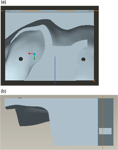
Following identification of the optimal alignment and osteotomy position, a navigational template was constructed with a 10-mm osteotomy gap and two drill guides to define the rotational alignment of the femur. Another tibial template was constructed with an 8-mm osteotomy gap. The template surfaces were created as the inverse of the distal femur and proximal tibia surfaces, thereby potentially enabling a near-perfect fit (). Using the computer, the distal femur and proximal tibia were cut along the gap, acquiring their virtual surfaces to allow measurement of the degree of matching following the actual osteotomy ().
Figure 3. Design of the navigational templates. (a) Virtual femoral template. (b) Virtual tibial template.
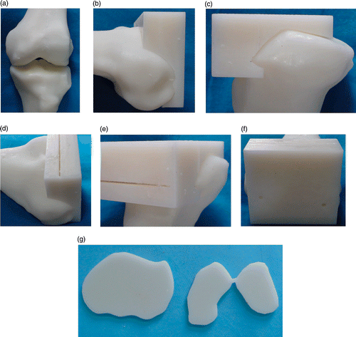
The desired femur and tibia biomodel, its corresponding navigational template, and the verification templates made in accordance with the virtual surfaces of the femur and tibia after osteotomy were produced in acrylate resin (Somos 14120; DSM Desotech, Inc., Elgin, IL) using stereolithography, a rapid-prototyping (RP) technique (Hen Tong Company, China). The accuracy of the navigational template was visually inspected before surgery. The femur and tibia biomodel and its corresponding template were fitted together to confirm their perfect fit ().
Figure 5. The accuracy of the navigational template was examined by visual inspection. (a) RP model of the femoral condyle and tibial plateau. (b) and (c) The navigational template fits the RP model of the knee perfectly. (d) and (e) The gap for the osteotomy in the navigational template. (f) The rotational alignment for the femur defined by the two drill guides. (g) RP model of the distal femur and proximal tibia surfaces after osteotomy in the actual physical setting.
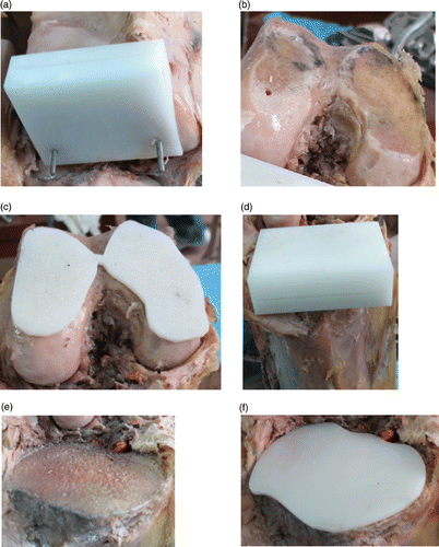
TKA was performed on all cadavers using the drill template. All operations were performed by the same surgeon (Y.G.). First, the femoral navigational template was placed on the femoral condyle and manually held in place by the surgeon. Two K-wire drill guides were made to mark the position of the rotational alignment (). Removing the two K-wires, the surgeon cut the distal femur along the gap in the template using an electric saw. The verification template was then placed to verify whether the actual section matched with the surface cutting in the virtual setting (). Next, the surgeon measured the femoral size and placed the conventional cutting block in accordance with the indicated rotational alignment to cut the anteroposterior condyle. The tibial navigational template was then placed on the tibial plateau and the proximal tibia was cut along the gap (). Finally, the verification template was placed to verify that the actual section fitted the surface cutting in the virtual setting ().
Figure 6. Cadaver undergoing TKA using the patient-specific navigational template technique. (a) The navigational template fits the femoral condyle perfectly. (b) and (c) The actual surface of the distal femur after osteotomy matches the surface shape from the virtual setting using the navigational template. (d) The navigational template fits the tibial plateau perfectly. (e) and (f) The actual surface of the proximal tibia after osteotomy matches the surface shape from the virtual setting using the navigational template.
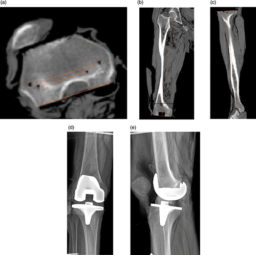
After surgery, the positions of the prostheses were evaluated with X-rays and CT scans by two surgeons (J.D. and D.X.) to obtain independent measurements of the extent of alignment violation ().
Figure 7. Imaging examination showing good positioning of the prosthesis. (a) The resection of the posterior surface is parallel to the transepicondylar axis. (b) and (c) The distal resection of the femur and the proximal resection of the tibia are almost perpendicular to the mechanical axis of the leg in the coronal plane. (d) and (e) X-rays of the knee in anteroposterior and lateral views following TKA showed normal alignment of the knee with an intact prosthesis.
Results
The accuracy of the navigational template was examined preoperatively by placing it on the femur and tibia. Each template was found to fit its corresponding biomodel appropriately.
During the operation, the best fit for positioning the template manually was easy to find because there was no significant free motion of the template when it was placed in position and pressed slightly against the femoral condyle and tibial plateau. Thus, the navigational template fulfilled its purpose for in situ osteotomy. Based on visual inspection, the actual surfaces obtained following osteotomy of the distal femur and proximal tibia matched perfectly the templates of the virtual surfaces without any violation.
Thirty knees underwent TKA. None of the cases had complications arising from the osteotomy of the distal femur and proximal tibia, and all the cut surfaces were nearly perpendicular to the mechanical alignment (within 0.5°), with the exception of two cases with 1–2° malpositioning and resection of the posterior surface parallel to the transepicondylar axis (). Using this novel, custom-fit navigational template, the operation was simplified and the operation time considerably reduced: on average, each TKA took approximately 50 min. This technique does not entail penetration of the intramedullary canals, thereby reducing blood loss and the risk of infection and marrow embolization. Currently, the production time for the RP model is approximately 2 days and the cost is approximately USD 60 per template, though it is anticipated that this cost can one day be reduced. In addition, the cost can be reduced to USD 40 if the RP model of the knee is deemed unnecessary.
Discussion
The use of drill templates was initially demonstrated in the hip and knee Citation[18], and there have also been several reports describing their use in spine surgeries, including operations on the cervical spine Citation[19–21]. This is the first study to assess the accuracy of a novel, patient-specific navigational template for TKA. It demonstrates the very high accuracy of the navigational template in both normal and abnormal mechanical leg-alignment settings.
There are numerous published studies on the importance of TKA alignment with regard to operating precision Citation[22–23]. The aim of TKA is to place the component perpendicular to the mechanical axis of the leg in the coronal plane Citation[24]. Resection of the posterior surface is undertaken to enable the posterior surface of the femoral component to be parallel to the transepicondylar axis in order to correct ligament balancing in flexion and extension Citation[25–27]. Studies have demonstrated that optimal alignment of the prosthesis can reduce complications and increase the long-term benefit following TKA Citation[28–31]. However, poor component alignment leads to abnormal wear and aseptic loosening Citation[32]. The question of how to locate the lower limb alignment and rotational axis accurately during the operation is the subject of ongoing debate.
The optimal range of the leg-axis deviation following TKA continues to be discussed in the literature; however, in the coronal plane, the femoral and tibial components should be positioned with an error of less than 3° Citation[33]. Traditionally, extramedullary alignment guides or intramedullary rods are used to obtain a neutral alignment for component orientation during TKA. Several studies have demonstrated that the conventional implantation technique fails in up to 30% of cases when restoring a mechanical limb axis within a range of 3° varus or valgus Citation[3], Citation[10]. Using conventional mechanical alignment guide systems, surgeons experience difficulty in installing knee implants within 2–3° of varus or valgus alignment and rotational alignment Citation[32], Citation[34]. Standard instrumentation, even when used by experts, does not achieve the correct arthroplasty alignment in 25% of cases, and the error may be as high as 10° in over 6% of cases because most instruments rely on indirect methods of obtaining a correct alignment using these techniques Citation[3]. First, the choice of the angle of the cut relative to the rod is often arbitrary. Secondly, the exact position of the center of the hip in three dimensions remains extremely difficult to determine in any individual patient, regardless of whether an intramedullary or extramedullary alignment technique is used. Extramedullary guidance, even when using a skin marker placed over the hip, is subject to rotational error. When introducing the intramedullary femoral alignment guide, the difficult reproducibility of the extramedullary tibial alignment guide leads to errors, especially in determining the ideal rotation of the components. Ritter et al. analyzed the outcome with regard to the femoro-tibial angle following TKA in 421 patients and concluded that the highest rate of aseptic loosening was seen in patients with a varus misalignment Citation[31]. Jeffery et al. analyzed 115 TKAs and found a prosthetic loosening rate of 24% when the mechanical axis exceeded ±3° varus/valgus deviation, compared to only 3% in knees with an axis within 3° of neutral Citation[35].
Recently, computer navigation systems have been used to increase the accuracy of implant positioning in knee arthroplasty. Several studies have demonstrated that these systems provide excellent value in terms of improving the longitudinal alignment of the limb compared to results with traditional alignment techniques Citation[6], Citation[12–15], Citation[24]. Other studies, however, have found no difference in performance Citation[36–39]. The navigation system guides the surgeon on the basis of the information supplied to the computer in terms of bone references and the positions of the ligaments. Meanwhile, the lower-limb mechanical alignment is determined intraoperatively, either by manipulating a joint to locate an average motion center or by touching bony landmarks with a digitizing probe. Mahaluxmivala et al. reported that senior surgeons cause the same number of positioning outliers as young surgeons when using a computer-assisted system Citation[3]. This may be due to difficulties in defining the correct landmarks during the operation, as well as during analysis of the images Citation[40–41]. Poor results can also be obtained using navigation because of other problems, including those involving the accuracy of the infrared diodes and software algorithm. Lionberger studied the various facets of electromagnetic technologies, pointing out the important weakness of signal distortion caused by any conductive material and the degradation of the signal in the presence of ferrous or magnetic material Citation[42]. In addition, the rigid body fixed on the skeleton keeps rotating during the operation, causing errors in all resection planes Citation[43]. Lutzner et al. investigated the outcomes following TKA in 80 patients, and found that, for rotational alignment of both components, the process was comparable in navigated and conventional TKA procedures so long as the same landmarks were used Citation[44]. This mirrors the results of Kim et al. Citation[39] and Hart et al. [38], who found no significant difference between computer-assisted navigated TKA and conventional TKA. Mastering this technique requires a great deal of time, and its use can lengthen the duration of surgical procedures. Moreover, the existing instability of the computer-assisted systems, their vulnerability to disruption, and their high cost also limit their widespread use, especially in developing countries.
The described template design is unique in that it is based on the reverse-engineering principle, and can therefore match the posterior surface of the femoral condyle and tibial plateau perfectly. All the templates can be held in place easily and securely by the surgeon's free hand.
The experiments have proven that the actual surfaces following osteotomy of the distal femur and proximal tibia were perfectly matched with the templates of the virtual surfaces with no violation, as verified through visual inspection. Using the novel patient-specific navigational cutting template, the cut surfaces obtained were all perpendicular to the mechanical alignment.
There are several advantages to using such patient-specific cutting template design. First, the surgeon can decide the alignment, location, orientation, and size of each prosthesis based on the CT data, even before reaching the operating table. Some authors have stated that the center of the medial epicondyle can be located by finger palpation, whereas others have argued that it is difficult to localize Citation[45]. Observations in the present study demonstrated that the femoral condyle may vary widely from patient to patient. Therefore, mandatory preoperative CT evaluation is recommended for precise planning of the surgical procedure. In the course of this study, abnormal femoral condyles were encountered in seven cases. Whether or not the medial epicondyle sulcus is detected, the centers of the femoral head and ankle joint and the medial epicondylar center can be determined accurately using preoperative CT to determine the alignment Citation[45]. Regarding the CT parameters, a smaller slice thickness generally provides greater accuracy, as demonstrated by stereotactic localization for brain surgery Citation[24]. The use of a patient-specific cutting template allows surgeons to handle even abnormal cases successfully by enabling them to resect the femoral distal and posterior surfaces and decide on the best orientation of the prosthesis insertion for each knee.
The second advantage of this technique is its simplicity of application; it does not require much expertise on the surgeon's part. The preoperatively prepared cutting template can be used intraoperatively to assist surgical navigation and precise placement of instrumentation. Thirdly, in contrast to the image guided approach, this technique eliminates the need for complex equipment and time-consuming procedures in the operating theater, thus reducing the duration of the surgical procedure. The fourth advantage is the non-penetration of the intramedullary canals, thereby reducing blood loss and the risk of infection and fat embolism.
Nevertheless, there are also some potential sources of errors with this technique. The template can produce fine particles as it is cut by the electric saw, so further improvement is required in that respect. Another issue is that, in the clinical setting, a template should be capable of being used as an in situ cutting guide. Any movement between the bone and the template resulting from vibration during the osteotomy will greatly affect accuracy. Therefore, the template has to be held firmly in position by the surgeon during the osteotomy.
Conclusion
This study has introduced a novel navigational template for use in TKA. The template requires further clinical validation, but the preliminary cadaveric trials have demonstrated that it can improve the accuracy of osteotomy in TKA. The unique feature of the design is that the template is created as the inverse of the femoral condyle and tibial plateau surfaces, thereby enabling a near-perfect fit in a lock-and-key fashion, which provides better stability in the clinical setting. With its wide applicability, high accuracy and cost-effectiveness, this design should enjoy widespread use in the future. However, the overall responsibility during a TKA procedure remains with the surgeon, and any auxiliary tool will only assist with the best technical positioning of the arthroplasty Citation[32].
Acknowledgments
The authors would like to thank Dr. Ping Zhou for his assistance with the CT data collection.
Declaration of interest: The authors report no conflict of interest. No benefits or funds were received in support of the study.
References
- Rodricks DJ, Patil S, Pulido P, Colwell CW Jr. Press-fit condylar design total knee arthroplasty: Fourteen to seventeen-year follow-up. J Bone Joint Surg Am 2007; 89–A: 89–95
- Vessely MB, Whaley AL, Harmsen WS, Schleck CD, Berry DJ. The Chitranjan Ranawat Award: Long-term survivorship and failure modes of 1000 cemented condylar total knee arthroplasties. Clin Orthop Relat Res 2006; 452: 28–34
- Mahaluxmivala J, Bankes MJ, Nicolai P, Aldam CH, Allen PW. The effect of surgeon experience on component positioning in 673 press fit condylar posterior cruciate-sacrificing total knee arthroplasties. J Arthroplasty 2001; 16: 635–640
- Mihalko WM, Boyle J, Clark LD, Krackow KA. The variability of intramedullary alignment of the femoral component during total knee arthroplasty. J Arthroplasty 2005; 20: 25–28
- Berger RA, Crossett LS, Jacobs JJ, Rubash HE. Malrotation causing patellofemoral complications after total knee arthroplasty. Clin Orthop Relat Res 1998; 356: 144–153
- Mihalko WM, Krackow KA. Difference between extramedullary, intramedullary, and computer-aided surgery tibial alignment techniques for total knee atrthroplasty. J Knee Surg 2006; 19: 33–36
- Siston RA, Patel JJ, Goodman SB, Delp SL, Giori NJ. The variability of femoral rotational alignment in total knee arthroplasty. J Bone Joint Surg Am 2005; 87: 2276–2280
- Jerosch J, Peuker E, Philipps B, Filler T. Interindividual reproducibility in preoperative rotational alignment of femoral components in knee prosthetic surgery using the transepicondylar axis. Knee Surg Sports Traumatol Arthrosc 2002; 10: 194–197
- Jenny JY, Boeri C. Low reproducibility of the intraoperative measurement of the transepicondylar axis during total knee replacement. Acta Orthop Scand 2004; 75: 74–77
- Petersen TL, Engh GA. Radiographic assessment of knee alignment after total knee arthroplasty. J Arthroplasty 1988; 3: 67–72
- Stulberg SD. How accurate is current TKR instrumentation?. Clin Orthop Relat Res 2003; 416: 177–184
- Bäthis H, Perlick L, Tingart M, Lüring C, Zurakowski D, Grifka J. Alignment in total knee arthroplasty. A comparison of computer-assisted surgery with the conventional technique. J Bone Joint Surg Br 2004; 86: 682–687
- Decking R, Markmann Y, Fuchs J, Puhl W, Scharf HP. Leg axis after computer navigated total knee arthroplasty: A prospective randomized trial comparing computer-navigated and manual implantation. J Arthroplasty 2005; 20: 282–288
- Chauhan SK, Scott RG, Breidahl W, Beaver RJ. Computer assisted knee arthroplasty versus a conventional jig-based technique: A randomized, prospective trial. J Bone Joint Surg Br 2004; 86–B: 372–377
- Delp SL, Stulberg SD, Davies B, Picard F, Leitner F. Computer assisted knee replacement. Clin Orthop Relat Res 1998; 354: 49–56
- Laskin RS. Instrumentation pitfalls: You just can’t go on autopilot!. J Arthroplasty 2003; 18(Suppl 1)18–22
- Novotny J, Gonzalez MH, Amirouche FM, Li YC. Geometric analysis of potential error in using femoral intramedullary guides in total knee arthroplasty. J Arthroplasty 2001; 16: 641–647
- Radermacher K, Portheine F, Anton M, Zimolong A, Kaspers G, Rau G, Staudte HW. Computer assisted orthopaedic surgery with image based individual templates. Clin Orthop Relat Res 1998; 354: 28–38
- Owen BD, Christensen GE, Reinhardt JM, Ryken TC. Rapid prototype patient-specific drill template for cervical pedicle screw placement. Comput Aided Surg 2007; 12(5)303–308
- Lu S, Xu YQ, Zhang YZ, Xie L, Guo H, Li DP. A novel computer-assisted drill guide template for placement of C2 laminar screws. Eur Spine J 2009; 18(9)1379–1385
- Lu S, Xu YQ, Lu WW, Ni GX, Li YB, Shi JH, Li DP, Chen GP, Chen YB, Zhang YZ. A novel patient-specific navigational template for cervical pedicle screw placement. Spine 2009; 34(26)E959–E964
- Wasielewski RC, Galante JO, Leightly R, Natarajan RN, Rosenberg RG. Wear patterns on retrieved polyethylene tibial inserts and their relationship to technical considerations during arthroplasty. Clin Orthop Relat Res 1993; 299: 31–43
- Lotke PA, Ecker ML. Influence of positioning of prosthesis in total knee replacement. J Bone Joint Surg Am 1977; 59–A: 77–79
- Nishihara S, Sugano N, Ikai M, Sasama T, Tamura S, Yoshikawa H, Ochi T. Accuracy evaluation of a shape-based navigation system for total knee arthroplasty. J Knee Surg 2003; 16: 98–105
- Churchill DL, Incavo SJ, Johnson CC, Beynnon BD. The transepicondylar axis appropriates the optimal flexion axis of the knee. Clin Orthop Relat Res 1998; 356: 111–118
- Olcott CW, Scott RD. Femoral component rotation during total knee arthroplasty. Clin Orthop Relat Res 1999; 367: 39–42
- Olcott CW, Scott RD. Determining proper femoral component rotational alignment during total knee arthroplasty. J Knee Surg 2000; 13: 166–168
- Hood RW, Vanni M, Insall JN. The correction of knee alignment in 225 consecutive total condylar knee replacements. Clin Orthop Relat Res 1994; 229: 32–43
- Arima J, Whiteside LA, McCarthy DS, White SE. Femoral rotational alignment, based on the antero-posterior axis, in total knee arthroplasty in a valgus knee: A technical note. J Bone Joint Surg Am 1995; 77–A: 1331–1334
- Eckhoff DG, Piatt BE, Gnadinger CA, Blaschko RC. Assessing rotational alignment in total knee arthroplasty. Clin Orthop Relat Res 1995; 318: 176–181
- Ritter MA, Fans PM, Keating EM. Postoperative alignment of total knee replacement: Its effect on survival. Clin Orthop Relat Res 1994; 299: 153–158
- Sharkey PF, Hozack WJ, Rothman RH, Shastri S, Jacoby SM. Why are total knee arthroplasties failing today?. Clin Orthop Relat Res 2002; 404: 7–13
- Mizu-uchi H, Matsuda S, Miura H, Okazaki K, Akasaki Y, Iwamoto Y. The evaluation of post-operative alignment in total knee replacement using a CT-based navigation system. J Bone Joint Surg Am 2008; 90: 1025–1031
- Teter KE, Bregman D, Colwell Jr CW. Accuracy of intramedullary versus extramedullary tibial alignment cutting systems in total knee arthroplasty. Clin Orthop Relat Res 1995; 321: 106–110
- Jeffery RS, Morris RW, Denham RA. Coronal alignment after total knee replacement. J Bone Joint Surg Br 1991; 73: 709–713
- Confalonieri N, Manzotti A, Pullen C, Ragone V. Computer-assisted technique versus intramedullary and extramedullary alignment systems in total knee replacement: a radiological comparison. Acta Orthop Belg 2005; 71: 703–709
- Spencer JM, Chauhan SK, Sloan K, Taylor A, Beaver RJ. Computer-navigation versus conventional total knee replacement: no difference in the functional results at two years. J Bone Joint Surg Br 2007; 89–B: 477–480
- Hart R, Janecek M, Chaker A, Bucek P. Total knee arthroplasty implanted with and without kinematic navigation. Int Orthop 2003; 27: 366–369
- Kim YH, Kim JS, Yoon SH. Alignment and orientation of the components in total knee replacement with and without navigation support: A prospective, randomized study. J Bone Joint Surg Br 2007; 89–B: 471–476
- Casino D, Zaffagnini S, Martelli S, Lopomo N, Bignozzi S, Iacono F, Russo A, Marcacci M. Intraoperative evaluation of total knee replacement: Kinematic assessment with a navigation system. Knee Surg Sports Traumatol Arthrosc 2009; 17: 369–373
- Matziolis G, Krocker D, Weiss U, Tohtz S, Perka C. A prospective, randomized study of computer-assisted and conventional total knee arthroplasty. Three-dimensional evaluation of implant alignment and rotation. J Bone Joint Surg Am 2007; 89: 236–243
- Lionberger R. The attraction of electromagnetic computer-assisted navigation in orthopaedic surgery. Navigation and MIS in Orthopaedic Surgery, JB Stiehl, W Konermann, R Hacker. Springer Verlag, Heidelberg 2006; 44–53
- Haaker RG, Stockheim M, Kamp M, Proff G, Breitenfelder J, Ottersbach A. Computer-assisted navigation increases precision of component placement in total knee arthroplasty. Clin Orthop Relat Res 2005; 433: 152–159
- Lutzner J, Krummenauer F, Wolf C, Gunther KP, Kirschner S. Computer-assisted and conventional total knee replacement. J Bone Joint Surg Br 2008; 90–B: 1039–1044
- Katz MA, Beck TD, Silber JS, Seldes RM, Lotke PA. Determining femoral rotational alignment in total knee arthroplasty: Reliability of techniques. J Arthroplasty 2001; 16: 301–305
