Abstract
A single-wire corona unipolar aerosol charger with a sheath air to avoid particle loss was designed and experimental charging efficiencies were obtained at a fixed aerosol flow rate of 1 L/min using monodisperse silver nanoparticles of 2.5 to 20 nm in diameter. The charger has a cylindrical casing of 30 mm in inner diameter in which a gold wire of 50 μm in diameter and 2 mm in length is used as the discharge electrode. A two-dimensional (2-D) numerical model was developed to predict nanoparticle charging efficiency in the unipolar charger. Laminar flow field was solved by using the Semi-Implicit Method for Pressure Linked Equations (SIMPLER method), while electric potential and ion concentration fields were solved on the basis of Poisson and convection–diffusion equations, respectively. The charged particle concentration fields and charging efficiencies were then calculated on the basis of the convection–diffusion equation in which ion–particle combination coefficient was calculated by Fuchs diffusion charging theory (Fuchs, N. A. (Citation1963). On the Stationary Charge Distribution on Aerosol Particles in a Bipolar Ionic Atmosphere. Geophys. Pura. Appl., 56:185–193). Good agreement between predicted and experimental extrinsic charging efficiencies was obtained. Numerical results showed the advantage of using sheath air to minimize charged particle loss and indicated the location where major charged particle loss occurred. It is expected that the present model can be used to facilitate the design of more efficient corona-wire unipolar charger in the future.
[Supplementary materials are available for this article. Go to the publisher's online edition of Aerosol Science and Technology to view the free supplementary files.]
INTRODUCTION
Aerosol particle charging has been applied in many different areas such as aerosol instrumentation, contamination control, and material synthesis (Friedlander and Pui Citation2004). Diffusion charging is one of the most commonly used techniques for charging nanoparticles. Because of low charging probabilities, nanoparticles are difficult to be charged. Once nanoparticles are charged, they can be easily lost within the charging device due to their high electrical mobility. Therefore, challenges in the design of a nanoparticle charger are to obtain high charging efficiency while minimizing particle loss (Chen and Pui Citation1999).
Corona discharge is widely used to produce unipolar ions at a high enough concentration for efficient diffusion charging (Hinds Citation1999). Numerous corona-based unipolar chargers were designed to achieve high charging efficiency using either a wire or a needle as the discharge electrode (Whitby Citation1961; Medved et al. Citation2000; Kruis and Fissan Citation2001; Hernandez-Sierra et al. Citation2003; Unger et al. Citation2004; Biskos et al. Citation2005a; Alonso et al. Citation2006; Qi et al. Citation2007, Citation2008; Kimoto et al. Citation2010; Park et al. 2010; Li and Chen Citation2011). However, the loss of charged nanoparticles is usually severe in the unipolar charger, resulting in only a small fraction of charged nanoparticles exiting the charger. Many corona-wire charger designs have an additional sheath airflow either near the wall of the charger to avoid particle loss or around the discharge wire to prevent accretion of particle (Liu and Pui Citation1975; Büscher et al. Citation1994; Cheng et al. Citation1997; Biskos et al. Citation2005b; Tsai et al. Citation2008, Citation2010).
Diffusion charging has been studied theoretically and various models are available. Detailed overview on the diffusion charging models in all aerosol regimes can be seen from the literature (Romay and Pui Citation1992; Biskos et al. Citation2004; Marquard Citation2007). In the transition regime (Knudsen number Kn≈1), the birth-and-death charging model (Boisdron and Brock Citation1970) with the ion–particle combination coefficient estimated by Fuchs diffusion charging theory (Fuchs Citation1963) was used to predict the charge distribution for the unipolar charger, assuming Nit condition is given where Ni is the ion concentration (ions/m3) and t is the residence time in seconds (Biskos et al. Citation2005b; Marquard et al. Citation2005; Qi et al. Citation2007, Citation2009; Vivas et al. Citation2008; Li and Chen Citation2011). The model assumes that ion concentration in the charging region is spatially uniform, considering neither the transport of ions and particles nor particle loss in the charger. These assumptions that are difficult to validate, especially for charging devices with complicated geometrical, electrical, and hydrodynamic conditions (Marquard et al. Citation2006), could lead to inaccurate predictions. By considering the transport effects of ions and particles, some numerical models (Aliat et al. Citation2008, Citation2009; Alonso et al. Citation2009) were able to simulate unipolar diffusion charging based on Fuchs theory in a tube flow with the simple plug flow assumption for the flow field. However, the models are not applicable to other unipolar chargers with more complicated geometry. Huang and Alonso (Citation2011) obtained particle trajectories through the combined mechanisms of diffusion and field charging to calculate nanoparticle electrostatic loss in the corona-needle unipolar charger for particles ranging from 3 to 30 nm in diameter. But the charging efficiency was not calculated. Kimoto et al. (Citation2010) developed a theoretical model based on Fuchs theory to predict the extrinsic charging efficiency of an efficient small mixing-type unipolar charger. The measured charging efficiencies for particles smaller than 10 nm were higher than the theoretical results due to the well-mixed flow assumption.
A comprehensive model, including the calculation of the flow, electrical potential, and ion concentration fields in the charging zone, is needed to predict the extrinsic charging efficiency and charged particle concentration field accurately (Qi et al. Citation2008). So far, no such detailed numerical models are currently available. Recently, Lin and Tsai (Citation2010) developed a two-dimensional (2-D) numerical model to predict the nanoparticle collection efficiency in single-stage wire-in-plate electrostatic precipitators (ESPs). The flow filed, electric potential, and ion concentration fields in the ESPs were solved first. The charged particle concentration field and particle collection efficiency were then calculated on the basis of the convection–diffusion equation in which particle charging was calculated by Fuchs theory. The numerical model of Lin and Tsai (Citation2010) was able to predict the experimental nanoparticle collection efficiency very well for particles smaller than 20 nm in diameter.
On the basis of the work of Lin and Tsai (Citation2010), the objective of this study is to develop a 2-D numerical model to predict nanoparticle charging efficiency in the unipolar charger, which was designed with a sheath airflow to avoid particle loss. The extrinsic charging efficiencies and particle charge distributions at the exit were obtained using monodisperse silver nanoparticles of 2.5–20 nm in diameter for model validation.
EXPERIMENTAL METHOD
Design of Unipolar Nanoparticle Charger
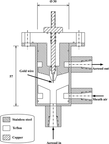
shows the schematic diagram of the present unipolar charger which is a modification of the nanoparticle charger with multiple discharging wires developed by Tsai et al. (Citation2010). The charger uses a gold wire of 50 μm in diameter and 2 mm in length as the discharge electrode, on which a high DC voltage is applied from the top of the charger. The outer stainless steel cylindrical casing of 30 mm in diameter is grounded. The space between the gold wire and the stainless steel casing is the charging zone where aerosol charging takes place. The aerosol flow was introduced into the charger from the bottom, and a filtered high-speed sheath airflow with the velocity of 0.9–7.1 m/s was introduced from an annular slit of 0.1-mm gap formed by the Teflon shroud and the outer casing to avoid charged particle loss. The charged particles were accelerated to exit the charger quickly through another annular slit of 0.1-mm gap after the charging zone.
Experimental Setup
The experimental setup shown in for measuring the charging efficiencies and particle losses in the charger is similar to that described in Tsai et al. (Citation2010). Monodisperse silver particles ranging from 2.5 to 20 nm in diameter were generated by the evaporation–condensation technique (Scheibel and Porstendörfer, 1983). First, silver powder was loaded in a ceramic boat placed in a tube furnace (Sunrise Co. Ltd., New Taipei City, Taiwan). Generated vapor was carried by clean air out of the furnace where polydisperse nanoparticles of high concentration were produced by quenching the hot vapor in a water-based cooler. The particles were neutralized by a TSI 3077A electrostatic charge neutralizer before being introduced into a nano-differential mobility analyzer (Nano-DMA, model 3085, TSI, Inc., Shoreview, MN, USA) for classifying monodisperse test particles. Singly charged monodisperse particles were then neutralized and passed through a wire-in-tube ESP to remove all charged particles, allowing only uncharged particles to enter the unipolar charger for the charging efficiency experiments.
FIG. 2 Schematic diagram of the experimental setup (HEPA, high efficiency particulate air; HV, high voltage).
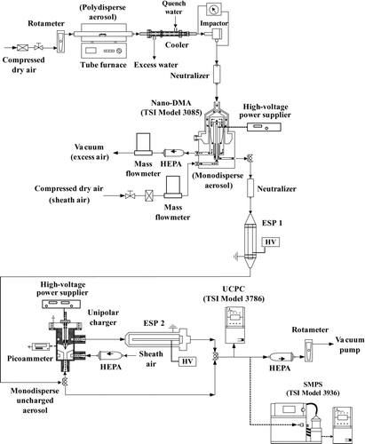
To generate the electric field and corona ions, high positive/negative voltage was supplied to the corona wire using a high-voltage DC power supplier (model SL P150/SL N30, Spellman High Voltage Electronic Corporation, NY, USA). The grounded stainless steel casing was connected to a picoammeter (model 6485, Keithley Instruments, Inc., Cleveland, OH, USA) for measuring the corona current. The high-speed sheath air from the annular slit near the casing wall helped accelerate charged particles to exit the charger. After charged aerosol flow exited the charger, it passed through the second ESP for removing charged particles if the voltage was turned on. An ultrafine condensation particle counter (UCPC, model 3786, TSI, Inc., Shoreview, MN, USA) was used to measure particle concentration downstream after the second ESP. For the experiment involving the measurement of particle charge distribution at the exit of the charger, the tandem-DMA method was used to measure the charge distribution of monodisperse particles of different sizes (Tsai et al. Citation2010).
Both particle charging efficiencies and particle losses were measured at the sheath airflow rates (Q sh) from 0.5 to 4.0 L/min while the aerosol flow was fixed at 1 L/min. There are four parameters used for the performance evaluation of unipolar electrical aerosol chargers (Marquard et al. Citation2006), including intrinsic charging efficiency (ηint), extrinsic charging efficiency (ηext), electrostatic loss (L el), and diffusion loss (L 0 d ). The superscript “0” represents uncharged particles. The intrinsic charging efficiency can be calculated as follows (Tsai et al. Citation2010):
The extrinsic charging efficiency is defined as the fraction of particles exiting the charger that carries at least one elementary unit of charge:
Experimental particle electrostatic loss, L el, and diffusion loss, L 0 d , inside the charger can be calculated as:
NUMERICAL METHOD
Flow Field
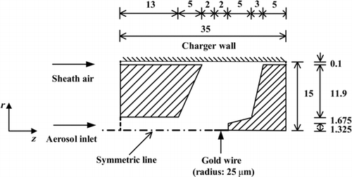
A 2-D numerical simulation was conducted in this study. The calculation domain of 35 mm in length and 15 mm in width is shown in , in which the hatched areas represent the solid region. The gap between the charger body and the wall is 0.1 mm for both sheath air and exiting aerosol flows. A total of 49,600 (248 in r-direction × 200 in z-direction) nonuniform rectangular grids were used in the calculation domain. The average grid size was about 60.5 and 175 μm in r (radial)- and z (axial)-direction, respectively, while the smallest size of 0.54 and 1.34 μm was assigned near the wire and the wall surfaces, respectively. In the test run, the number of grids was either 12,400 (124 × 100), 49,600 (248 × 200), or 198,400 (496 × 400). As the number of grids was increased from 12,400 to 49,600 or 198,400, the accuracy for the numerical diffusion loss of 5-nm particles at Q sh = 3 L/min was also changed from 20.1% to 18.6% or 18.4%. With the number of grids of 49,600 and the computation time for the flow field of about 3 h, the calculated diffusion loss of 5-nm particles at Q sh = 3 L/min was found to be close to the experimental data of 17.9%. Further increase in the number of grids to 198,400, the diffusion loss only changed by about 0.2 % but the computation time for the flow field was increased to about 48 h. Therefore, 49,600 grids were used in the current simulation. The total number of iterations to reach convergence was about 10,000 for solving the flow field.
The laminar flow field model was used since the maximum flow Reynolds number based on the hydrodynamic diameter is 235.8, which is much smaller than 2000. The flow field in the charger was simulated by solving the 2-D Navier–Stokes equations and continuity equation in the cylindrical coordinates (Equations (S1)–(S3)). The governing equations were discretized using the finite volume method and solved by the Semi-Implicit Method for Pressure Linked Equations algorithm (SIMPLER; Patankar Citation1980). When dealing with the boundary at the inclined wall surface, the concept of blocked-off region was applied to divide the control volumes into active and inactive regions, the later of which represent solid regions. At the inlets of aerosol and sheath flows, the boundary conditions for the calculation of flow field were assigned on the basis of the experimental values. The outflow velocity at the exit of the charger was calculated on the basis of the continuity equation.
Electric Potential and Ion Concentration Fields
The present methods for calculating corona discharge and ion concentration field were based on the work of Lin and Tsai (Citation2010). The governing equation, Poisson's equation, for the electric potential field in the charger can be written as
The space charge density, ρi , in EquationEquation (5), was calculated by the following convection–diffusion equation as
Charged Particle Concentration Field and Particle Charging Efficiency
The governing equation for the concentration of particles carrying q elementary charges, Np,q , is
Equations (5), (6), and (11) were also discretized by using the finite volume method and solved by the same computer code used in the flow field simulation. No numerical diffusion is expected to occur since the same computer code was used successfully in our previous studies to solve particle transport equations for convection, diffusion, and thermophoresis (Lin and Tsai Citation2003; Lin et al. Citation2004, Citation2008). The extrinsic charging efficiency, electrostatic loss, and convection–diffusion loss (Lc con-dif) of charged particles in the charger were then calculated as follows (Marquard et al. Citation2006):
RESULTS AND DISCUSSION
Characteristics of the V-I Curve
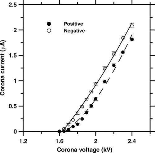
shows the corona current as a function of applied voltage in the present charger. The corona current varied from 0.001 to 1.817 and −0.004 to −2.087 μA at the applied voltage of +1.6 to + 2.4 and −1.6 to −2.4 kV, respectively. For an aerosol charger based on the ion attachment technique, the Nit product is the key parameter when the charging mechanism is dominated by ion diffusion. A greater Nit product will lead to higher intrinsic charging efficiency. Numerical results showed that the maximum ion concentration occurred at the discharge wire surface, which ranged 1.10×10¹³to1.49×1016 ions/m3 at the positive applied voltage of +1.6 to +2.4 kV and 3.04×10¹³to1.47×1016 ions/m3 at the negative applied voltage of −1.6 to −2.4 kV, respectively. The average residence time in the charging zone was calculated to be 0.222–0.067 s when the sheath airflow rate varied from 0.5 to 4 L/min at the fixed aerosol flow rate of 1 L/min. Therefore, both sheath airflow rate and applied voltage will influence the intrinsic charging efficiency. A smaller flow rate and higher applied voltage will lead to a higher Nit product and hence a higher intrinsic charging efficiency. But for the extrinsic charging efficiency, the loss of charged particles inside the charger also has to be considered.
Effect of Sheath Airflow Rate
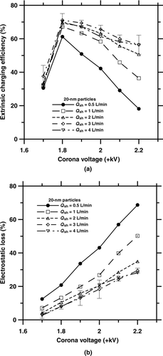
The effect of the sheath airflow rate (Q sh) on the extrinsic charging efficiency was obtained experimentally. shows the experimental extrinsic charging efficiency of 20-nm particles as a function of corona voltage and sheath airflow rate. At all sheath airflow rates, there is a corresponding maximum extrinsic charging efficiency that occurs at +1.8 kV. In general, the extrinsic charging efficiency of 20-nm particles increases with increasing sheath airflow rate from 0.5 to 3 L/min due to a decrease in the residence time and the reduction of charged particle loss. For example, at the applied voltage of +1.8 kV, the extrinsic charging efficiency of 20-nm particles was found to increase from 61.2% to 71.1% when Q sh was increased from 0.5 to 3 L/min. However, further increase of Q sh from 3 to 4 L/min did not increase the extrinsic charging efficiency any further. For example, at +1.8 kV, the extrinsic charging efficiency was 70.1% at Q sh = 4 L/min, which was very close to 71.1% at Q sh = 3 L/min. As also shown in , the electrostatic loss of 20-nm charged particles is decreased with an increasing Q sh from 0.5 to 3 L/min at the applied voltage from +1.7 to +2.2 kV. The electrostatic loss in the charger was effectively reduced at Q sh = 3 L/min, but did not change very much when Q sh was increased to 4 L/min. However, by increasing Q sh to 4 L/min, electrostatic loss did not decrease further for the applied voltage below +1.9 kV. The loss was increased instead when the applied voltage was greater than +1.9 kV. The highest extrinsic charging efficiency for 20-nm particles was thus obtained at 3 L/min.
FIG. 5 (a) Experimental extrinsic charging efficiency and (b) electrostatic loss of 20-nm particles versus corona voltage at different sheath airflow rates.
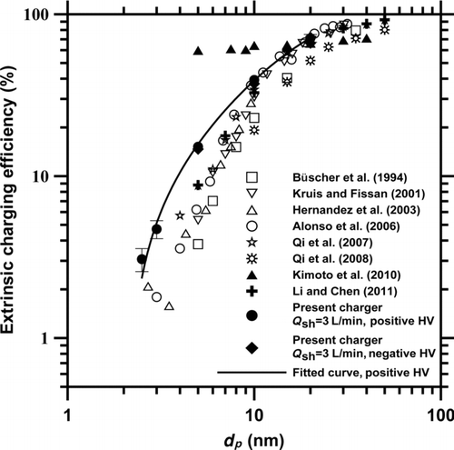
The maximum extrinsic charging efficiencies of the present charger operating at Q sh = 3 L/min are compared with those of previous corona-based chargers and shown in . The best extrinsic charging efficiency of the present charger was 3.1%–71.1% (dp = 2.5–20 nm) at the positive applied voltages of +1.8 to +2.1 kV, and 14.7%–66.4% (dp = 5–20 nm) at the negative applied voltages of −1.8 to −2.1 kV. The extrinsic charging efficiencies of the present charger are seen to be higher than those of other corona-based unipolar chargers, but lower than those of Kimoto et al. (Citation2010) for particles smaller than 10 nm in diameter. The charger developed by Kimoto et al. (Citation2010) consisted of a high-pressure corona ionizer to generate unipolar ions and a small charging chamber (0.5 cm3 volume) where the ions were mixed with nanoparticles without an external electric field.
FIG. 6 Comparison of the extrinsic charging efficiencies of the present charger with those of previous corona-based chargers.
Flow Streamlines, Electric Potential, Ion Concentration, and Charged Particle Concentration Fields
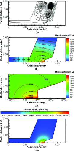
The flow field, electric potential, and ion concentration fields were calculated first before the charged particle concentration could be calculated. An example of the calculated flow field (plotted as flow streamlines), electric potential, and ion number concentration fields is shown in for the present charger at Q sh = 3 L/min at the applied voltage of −2.1 kV. shows two main flow recirculation regions exist in charging zone of the charger, which have a great influence on the spatial distribution of charged particles as will be shown later. Both calculated electric potential and ion concentration are seen to be the highest near the wire but decay very rapidly away from the wire. The equipotential lines are also seen to be close to each other near the wire where the electric field is the strongest. Without considering the transport effect of flow field, ions and charged particles will move along the electric field lines, which are perpendicular to the equipotential lines in the charger, and then attach to the charger wall. The ion number concentration is the maximum at the wire surface, which is 8.68×10¹⁵ ions/m3 at the axial distance of 0.02 ∼ 0.022 m and decays to about 2.5×10¹⁵ ions/m3 at the radial distance of 0.003 m and 3.4×10¹⁴ ions/ m3 near the wall at the same axial position.
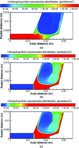
On the basis of the flow, electric potential, and the ion concentration fields, the spatial distribution of charged particles in the charger was calculated. An example is shown for 20-nm particles carrying 0–2 charges at the applied voltage of −2.1 kV in –c. In , the ion molecular weight was assumed to be 0.050 kg/mol (Adachi at el. 1985) and the inlet particle concentration, 2×10⁹ particles/m3, was taken from the experimental data. As shown in the figure, the concentration of particles with 0 charge decreases with an increasing axial distance from the entrance of the charging zone, where some particles are charged by negative ions to acquire 1–2 charges. The pattern of the charged particle concentration field resembles that of the flow field shown in , and most charged particle loss is seen to occur on the inclined wall surface on the right-hand side where the charged particle concentration is gradually decreased due to electrostatic deposition, leading to a lower charged particle concentration at the charger outlet than that in the charging zone. That is, the extrinsic charging efficiency will be lower than the intrinsic charging efficiency. The current numerical results show that flow field in the charger is important to the electrostatic loss of charged particles. Further improvement of the charger to minimize the recirculation regions is an important consideration to reduce the electrostatic loss and increase the extrinsic charging efficiency.
Charging Efficiency and Electrostatic Loss
and b shows the comparison of the extrinsic charging efficiency between the numerical results and experimental data of the present charger at Q sh = 3 L/min. The values of ion molecular weights of positive and negative ions in the open literature shown in table 1 of Lin and Tsai (Citation2010) were also used to examine the effect of the ion molecular weight on the charging efficiency and electrostatic loss in the present simulation. Results show that the extrinsic charging efficiency increases with an increasing particle diameter for both positive and negative applied voltages. However, a higher applied voltage did not result in a higher extrinsic charging efficiency for a given particle diameter. For example, when the applied voltage was increased from +1.9 to +2.0 kV, the experimental extrinsic charging efficiency was found to increase from 29.7% to 39.3% for 10-nm particles but decrease from 69.4% to 65.7% for 20-nm particles. When the applied voltage was further increased from +2.0 to +2.1 kV, the experimental extrinsic charging efficiency was found to decrease from 39.3% to 34.1% for 10-nm particles but decrease from 65.7% to 60.0% for 20-nm particles. Hence, there exists an optimum applied voltage depending on particle size, at which the extrinsic charging efficiency is the maximum.
FIG. 9 Comparison of the extrinsic charging efficiency of the present charger between the numerical results and experimental data at Q sh = 3 L/min. (a) Positive voltage, (b) negative voltage.
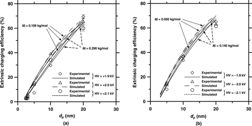
FIG. 10 Comparison of the electrostatic loss of the present charger between the numerical results and experimental data at Q sh = 3 L/min. (a) Positive voltage, (b) negative voltage.
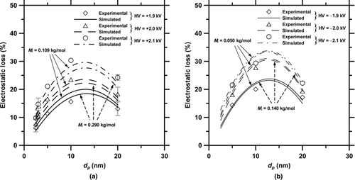
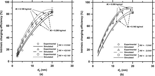
FIG. 11 Comparison of the intrinsic charging efficiency of the present charger between the numerical results and experimental data at Q sh = 3 L/min. (a) Positive voltage, (b) negative voltage.
In and b, the predicted extrinsic charging efficiencies are shown to be in good agreement with the experimental data with a deviation of 0.4%–5.3% and 0.7%–7.0%, respectively, at positive and negative applied voltages. Within the range of positive ion molecular weight from 0.109 to 0.290 kg/mol, numerical results show that there are no significant differences in the extrinsic charging efficiency when different ion molecular weights are used. The calculated extrinsic charging efficiency ranges from 5.4% ∼ 5.9% to 4.9% ∼ 5.6% for 2.5-nm particles, from 5.8% ∼ 8.2% to 5.4% ∼ 7.8% for 3-nm particles, from 9.5% ∼ 14.8% to 8.7% ∼ 14.5% for 5-nm particles, from 34.5% ∼ 40.0% to 32.8% ∼ 36.8% for 10-nm particles, and from 64.0% ∼ 67.4% to 62.7% ∼ 65.7% for 20-nm particles, respectively, at the applied voltage of +1.9 ∼ +2.1 kV. This is because a lower ion molecular weight leads to a higher charging level at a given ion mobility. Similar trend is also found at negative applied voltages, as shown in . Because of higher mobility of negative ions, the predicted charging efficiency is slightly higher for negative polarity than that for the positive polarity, which is to be expected.
and b shows the comparison of the electrostatic loss of charged particles between the numerical values and experimental data at Q sh = 3 L/min. The maximum electrostatic loss is seen to occur at c.a. 10-nm particles at both positive and negative applied voltages. It is because the charged fraction of particles less than 10 nm in diameter decreases with decreasing particle diameter, while the electrical mobility of particles larger than 10 nm decreases as the particle size is increased (Alonso et al. Citation2006; Tsai et al. Citation2010). Again, no significant differences in the electrostatic loss are observed when different ion molecular weights are used. Besides, the simulated convection–diffusion loss of charged particles was found to be insignificant compared with the electrostatic loss, and thus it can be safely neglected (data not shown). This finding is consistent with that found by Alonso et al. (Citation2006).
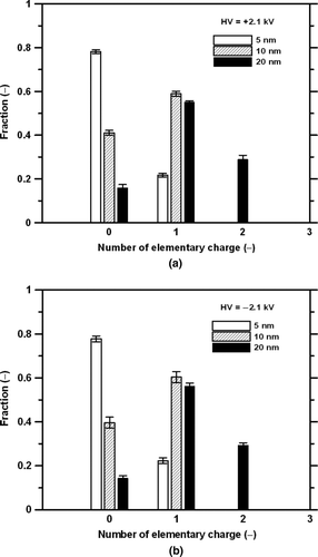
FIG. 12 Measured charge distribution at the exit of the present charger at Q sh = 3 L/min at the applied voltage of (a) +2.1 kV and (b) −2.1 kV.
By EquationEquation (17), the simulated intrinsic charging efficiencies were calculated and compared with the experimental data as shown in and b. Results show that the intrinsic charging efficiencies increase with an increasing corona voltage and particle diameter. The present numerical results agree well with the experimental intrinsic charging efficiencies at both positive and negative applied voltages. The experimental intrinsic charging efficiencies of 20-nm particle reach up to 84.2% and 83.7% at the applied voltage of +2.1 and −2.1 kV, respectively. However, for particles with dp <10 nm, the intrinsic charging efficiency of the present charger is not high enough to achieve a higher extrinsic charging efficiency even if the charged particle loss is minimized in the future. In this case, increasing the intrinsic charging efficiency is also essential to the improvement of the extrinsic charging efficiency for particles less than 10 nm in diameter.
Particle Charge Distribution
In addition to the extrinsic charging efficiency, the charge distributions at the exit of the charger for monodisperse particles of different sizes were measured and simulated. An example of the measured charge distribution for particles of 5, 10, and 20 nm at the exit of the present charger is shown in and b at Q sh = 3 L/min and the applied voltage of +2.1 and −2.1 kV, respectively. Results show that the particles are either singly charged or uncharged for dp <10 nm. Multiple charged particles with up to two charges are observed for 20-nm particles. For example, at the applied voltage of −2.1 kV, the fraction of 20-nm particles carrying 0, 1, and 2 charges at the exit is 0.15, 0.56, and 0.29, respectively, which is very close to 0.14, 0.54, and 0.32 calculated from the numerical number concentration field shown in .
CONCLUSION
This study developed a detailed 2-D numerical model to predict the flow, electric potential, ion concentration, charged particle concentration fields, charged particle losses, and charging efficiencies in a single-wire corona unipolar charger. Sheath air was added near the wall to avoid charged particle loss. Experimental results show that the present charger has a good extrinsic charging efficiency of 3.1%–71.1% for particles ranging from 2.5 to 20 nm in diameter at the sheath airflow rate of 3 L/min. The predicted extrinsic charging efficiencies are shown to be in good agreement with the experimental data. Numerical results indicate the location where the major charged particle loss occurs inside the charger and further show that flow field is important to the electrostatic loss of charged particles. However, since corona discharge is involved in the current charger, it is to be noted that new particles may be generated by gas-to-particle conversion process if contaminants (such as volatile organic vapors) are present inside the charger.
The present validated numerical model enables the design of an efficient corona-wire unipolar charger in the future. Future research directions include minimizing flow recirculation zones inside the charger to reduce charged particle loss and increasing Nit product to increase the intrinsic charging efficiency. In addition, the validation of the extrinsic charging efficiency and charge distribution for monodisperse particles with dp >20 nm will be explored using the present model. For the charger with sheath flow near the discharge wire, the physical dimension may be changed and the resulting field may be distorted over time. This is also worth investigating in the future.
uast_a_600785_sup_20016771.zip
Download Zip (57.5 KB)Acknowledgments
The financial support of this work by the Taiwan National Science Council (NSC96-2628-E-009-008-MY3 and NSC99-2221-E-009-038-MY3) is gratefully acknowledged.
REFERENCES
- Adachi , M. , Kousaka , Y. and Okuyama , K. 1985 . Unipolar and Bipolar Diffusion Charging of Ultrafine Aerosol Particles . J. Aerosol. Sci. , 16 : 109 – 123 .
- Aliat , A. , Tsai , C. J. , Hung , C. T. and Wu , J. S. 2008 . Effect of Free Electrons on Nanoparticle Charging in a Negative Direct Current Corona Charger . Appl. Phys. Lett. , 93 : 154103
- Aliat , A. , Hung , C. T. , Tsai , C. J. and Wu , J. S. 2009 . Implementation of Fuchs’ Model of Ion Diffusion Charging of Nanoparticles Considering the Electron Contribution in DC-Corona Chargers in High Charge Densities . J. Phys. D: Appl. Phys. , 42 : 125206
- Alonso , M. , Martin , M. I. and Alguacil , F. J. 2006 . The Measurement of Charging Efficiencies and Losses of Nanoparticles in a Corona Charger . J. Electrostat. , 64 : 203 – 214 .
- Alonso , M. , Alguacil , F. J. and Borra , J. P. 2009 . A Numerical Study of the Influence of Ion-Aerosol Mixing on Unipolar Charging in a Laminar Flow Tube . J. Aerosol. Sci. , 40 : 693 – 706 .
- Biskos , G. , Mastorakos , E. and Collings , N. 2004 . Monte-Carlo Simulation of Unipolar Diffusion Charging for Spherical and Non-Spherical Particles . J. Aerosol. Sci. , 35 : 707 – 730 .
- Biskos , G. , Reavell , K. and Collings , N. 2005a . Electrostatic Characterisation of Corona-Wire Aerosol Chargers . J. Electrostat. , 63 : 69 – 82 .
- Biskos , G. , Reavell , K. and Collings , N. 2005b . Unipolar Diffusion Charging of Aerosol Particles in the Transition Regime . J. Aerosol. Sci. , 36 : 247 – 265 .
- Boisdron , Y. and Brock , J. R. 1970 . On the Stochastic Nature of the Acquisition of Electrical Charge and Radioactivity by Aerosol Particles . Atmos. Environ. , 4 : 35 – 50 .
- Büscher , P. , Schmidt-Ott , A. and Wiedensohler , A. 1994 . Performance of a Unipolar “Square Wave” Diffusion Charger with Variable nt-Product . J. Aerosol Sci. , 25 : 651 – 663 .
- Chen , D. R. and Pui , D. Y. H. 1999 . A High Efficiency, High Throughput Unipolar Aerosol Charger for Nanoparticles . J. Nanopart. Res. , 1 : 115 – 126 .
- Cheng , S. H. , Ranade , M. B. and Gentry , J. W. 1997 . Experimental Design of High Volume Electrostatic Charger . Aerosol Sci. Technol. , 26 : 433 – 446 .
- Friedlander , S. K. and Pui , D. Y. H. 2004 . Emerging Issues in Nanoparticle Aerosol Science and Technology . J. Nanopart. Res. , 6 : 313 – 320 .
- Fuchs , N. A. 1963 . On the Stationary Charge Distribution on Aerosol Particles in a Bipolar Ionic Atmosphere . Geophys. Pura. Appl. , 56 : 185 – 193 .
- Hernandez-Sierra , A. , Alguacil , F. J. and Alonso , M. 2003 . Unipolar Charging of Nanometer Aerosol Particles in a Corona Ionizer . J. Aerosol. Sci. , 34 : 733 – 745 .
- Hinds , W. C. 1999 . Aerosol Technology , New York : John Wiley .
- Huang , C. H. and Alonso , M. 2010 . Nanoparticle Electrostatic Loss Within Corona Needle Charger During Particle-Charging Process . J. Nanopart. Res. , 13 : 175 – 184 .
- Kaptzov , N. A. 1947 . Elektricheskiye Yavleniya v Gazakh i Vacuume , Moscow : OGIZ .
- Kimoto , S. , Saiki , K. , Kanamaru , M. and Adachi , M. 2010 . A Small Mixing-Type Unipolar Charger (SMUC) for Nanoparticles . Aerosol Sci. Technol. , 44 : 872 – 880 .
- Kruis , F. E. and Fissan , H. 2001 . Nanoparticle Charging in a Twin Hewitt Charger . J. Nanopart. Res. , 3 : 39 – 50 .
- Li , L. and Chen , D. R. 2011 . Performance Study of a DC-Corona-Based Particle Charger for Charge Conditioning . J. Aerosol. Sci. , 42 : 87 – 99 .
- Lin , G. Y. and Tsai , C. J. 2010 . Numerical Modeling of Nanoparticle Collection Efficiency of Single-Stage Wire-in-Plate Electrostatic Precipitators . Aerosol Sci. Technol. , 44 : 1122 – 1130 .
- Lin , J. S. and Tsai , C. J. 2003 . Thermophoretic Deposition Efficiency in a Cylindrical Tube Taking into Account Developing Flow at the Entrance Region . J. Aerosol Sci. , 34 : 569 – 583 .
- Lin , J. S. , Tsai , C. J. and Chang , C. P. 2004 . Suppression of Particle Deposition in Tube Flow by Thermophoresis . J. Aerosol Sci. , 35 : 1235 – 1250 .
- Lin , J. S. , Tsai , C. J. , Tung , K. L. and Chiang , H. C. 2008 . Thermophoretic Particle Deposition Efficiency in Turbulent Tube Flow . J. Chin. Inst. Chem. Eng. , 39 : 281 – 285 .
- Liu , B. Y. H. and Pui , D. Y. H. 1975 . On the Performance of the Electrical Aerosol Analyzer . J. Aerosol Sci. , 6 : 249 – 264 .
- Marlow , W. H. and Brock , J. R. 1975 . Unipolar Charging of Small Aerosol Particles . J. Coll. Interface Sci. , 50 : 32 – 38 .
- Marquard , A. 2007 . Unipolar Field and Diffusion Charging in the Transition Regime—Part I: A 2-D Limiting-Sphere Model . Aerosol Sci. Technol. , 41 : 597 – 610 .
- Marquard , A. , Kasper , M. , Meyer , J. and Kasper , G. 2005 . Nanoparticle Charging Efficiencies and Related Charging Conditions in a Wire-Tube ESP at DC Energization . J. Electrostat. , 63 : 693 – 698 .
- Marquard , A. , Meyer , J. and Kasper , G. 2006 . Characterization of Unipolar Electrical Aerosol Chargers—Part I: A Review of Charger Performance Criteria . J. Aerosol Sci. , 37 : 1052 – 1068 .
- Medved , A. , Dorman , F. , Kaufman , S. L. and Pocher , A. 2000 . A New Corona-Based Charger for Aerosol Particles . J. Aerosol Sci. , 31 : S616 – S617 .
- Patankar , S. V. 1980 . Numerical Heat Transfer and Fluid Flow , Washington, DC. : Hemisphere .
- Peek , F. W. 1929 . Dielectric Phenomena in High-Voltage Engineering , New York : McGraw-Hill .
- Pui , D. Y. H. , Fruin , S. and McMurry , P. H. 1988 . Unipolar Diffusion Charging of Ultrafine Aerosols . Aerosol Sci. Technol. , 8 : 173 – 187 .
- Qi , C. , Asbach , C. , Shin , W. G. , Fissan , H. and Pui , D. Y. H. 2009 . The Effect of Particle Pre-Existing Charge on Unipolar Charging and Its Implication on Electrical Aerosol Measurements . Aerosol Sci. Technol. , 43 : 232 – 240 .
- Qi , C. , Chen , D. R. and Greenberg , P. 2008 . Performance Study of a Unipolar Aerosol Mini-Charger for a Personal Nanoparticle Sizer . J. Aerosol Sci. , 39 : 450 – 459 .
- Qi , C. , Chen , D. R. and Pui , D. Y. H. 2007 . Experimental Study of a New Corona-Based Unipolar Aerosol Charger . J. Aerosol Sci. , 38 : 775 – 792 .
- Romay , F. J. and Pui , D. Y. H. 1992 . On the Combination Coefficient of Positive Ions with Ultrafine Neutral Particles in the Transition and Free-Molecule Regimes . Aerosol Sci. Technol. , 17 : 134 – 147 .
- Scheibel , H. G. and Porstendörfer , J. 1983 . Generation of Monodisperse Ag- and NaCl-Aerosol with Particle Diameters Between 2 and 300 nm . J. Aerosol Sci. , 14 : 113 – 126 .
- Tsai , C. J. , Chen , S. C. , Chen , H. L. , Chein , H. M. , Wu , C. H. and Chen , T. M. 2008 . Study of a Nanoparticle Charger Containing Multiple Discharging Wires in a Tube . Sep. Sci. Technol. , 43 : 3476 – 3493 .
- Tsai , C. J. , Lin , G. Y. , Chen , H. L. , Hunag , C. H. and Alonso , M. 2010 . Enhancement of Extrinsic Charging Efficiency of a Nanoparticle Charger with Multiple Discharging Wires . Aerosol Sci. Technol. , 44 : 807 – 816 .
- Unger , L. , Boulaud , D. and Borra , J. P. 2004 . Unipolar Field Charging of Particles by Electric Discharge: Effect of Particle Shape . J. Aerosol Sci. , 35 : 965 – 979 .
- Vivas , M. M. , Hontañón , E. and Schmidt-Ott , A. 2008 . Reducing Multiple Charging of Submicron Aerosols in a Corona Diffusion Charger . Aerosol Sci. Technol. , 42 : 97 – 109 .
- Whitby , K. T. 1961 . Generator for Producing High Concentrations of Small Ions . Rev. Sci. Instrum. , 32 : 1351 – 1355 .
