21,896
Views
438
CrossRef citations to date
0
Altmetric
Perspective Paper

Heterostructured materials: superior properties from hetero-zone interaction

, , , , , ORCID Icon, , , , , ORCID Icon, & show all
Pages 1-31 | Received 20 Jun 2020, Published online: 27 Sep 2020

ABSTRACT

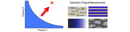
Heterostructured materials are an emerging class of materials with superior performances that are unattainable by their conventional homogeneous counterparts. They consist of heterogeneous zones with dramatic (>100%) variations in mechanical and/or physical properties. The interaction in these hetero-zones produces a synergistic effect where the integrated property exceeds the prediction by the rule-of-mixtures. The heterostructured materials field explores heterostructures to control defect distributions, long-range internal stresses, and nonlinear inter-zone interactions for unprecedented performances. This paper is aimed to provide perspectives on this novel field, describe the state-of-the-art of heterostructured materials, and identify and discuss key issues that deserve additional studies.

IMPACT STATEMENT

This paper delineates heterostructured materials, which are emerging as a new class of materials with unprecedented properties, new materials science and economic industrial production.

GRAPHICAL ABSTRACT

This article is part of the following collections:
Heterostructured Materials

Heterostructured materials are quickly emerging as a major material research topic, because they not only possess superior mechanical and physical properties that are not attainable by conventional homogeneous materials, but also present new materials science that challenges our conventional understanding and intuition. In addition, heterostructured materials can be processed using current industrial facilities, making it conducive to industrial production at low cost [Citation1]. In this paper we primarily focus on structural heterostructured materials because they have been studied more extensively than functional heterostructured materials. This paper is arranged in the following order: Section 1 defines heterostructured materials; Section 2 introduces the fundamental principles of structural heterostructured materials; Section 3 overviews the processing and properties of different types of heterostructures and related properties; Section 4 overviews the modeling of heterostructured materials; Section 5 outlines future issues to be studied for structural heterostructured materials; Section 6 overviews the functional heterostructured materials.

1. Definition of heterostructured materials

Heterostructured (HS) materials are defined as materials that contain heterogeneous zones that have dramatically different constitutive properties in the case of structural metallic materials [Citation1,Citation2] or alternatively, very different physical properties in the case of functional materials. Experiments have demonstrated that both structural and functional materials can benefit from the synergistic effect arising from the interaction and coupling between these heterogeneous zones. For example, the trade-off in strength and ductility can be alleviated or even avoided in heterostructured metals [Citation3,Citation4]. Moreover, superior functional properties have also been realized in heterostructured functional materials [Citation5–8]. These examples represent successful attempts to address classic challenges that cannot be solved via existing paradigms described in textbooks.

To distinguish the HS materials from those conventional materials, we define the scope of heterostructured materials as materials whose inter-zone interactions/couplings produce significant synergistic effect. All conventional materials have heterogeneities to varying extent. For example, the sizes and orientations of grains in metals usually have statistical distributions. Conventional alloys, such as steels and high-strength Al alloys, often contain second-phases or hard precipitates in various sizes. Although these heterogeneities may produce significant strengthening, the synergistic effect between heterogeneities is often weak and not well studied from the angle of inter-zone interaction/coupling. Heterogeneous zones need to be in appropriate size, geometry and distribution in order for the synergistic effect to be significant.

2. Structural heterostructured materials—fundamentals

During plastic deformation of heterostructured materials, the hetero-zones deform inhomogeneously, generating back stresses in the soft zones and forward stresses in the hard zones, which together produce hetero-deformation induced (HDI) strengthening that increases yield strength and enhances strain hardening, which aids with retaining ductility [Citation2]. HDI hardening originates from the mutual constraint of the hard and soft zones, and is superimposed on conventional dislocation hardening to help improves ductility. Back stress is a long-range internal stress produced by geometrically necessary dislocations (GNDs), sometimes in the form of dislocation pileups. It usually acts to offset the applied stress to impede dislocation emission and slip in the soft zones, which makes the soft zones appear to be stronger. Forward stress is created in the hard zones due to the stress concentration at the zone boundary caused by the GND pileup. During the early stages of elastoplastic deformation before global yielding (typically defined as 0.2% global plastic strain for conventional materials), the hard zones remain elastic and back stress plays a dominant role in enhancing the global yield strength in heterostructured materials. It should be noted that HDI stress is also called kinematic stress in the field of mechanics [Citation9].

There are several major approaches that can be implemented to enhance global yield strength including: (1) reduction of dislocation mobility; (2) manipulation of dislocation nucleation sites; (3) redistribution of stress away from soft (plastically-deforming) to hard (non-deforming) zones. HDI hardening is an example of the approach (3). The most interesting scenarios arise from coupling between all three methods. For example, stress redistribution can create local deformation paths that are nonproportional, leading to enhanced levels of work-hardening not achievable in structurally homogeneous materials. In nano-grained metals, the large grain-to-grain variation in dislocation source strengths creates a heterostructured material with soft and hard grains [Citation10,Citation11].

Strain gradients tend to develop near zone boundaries between soft and hard zones during deformation [Citation1–3,Citation12–14]. Soft zones are constrained by adjacent hard zones and subjected to higher plastic strain than hard zones [Citation3]. Across a zone boundary, the in-plane components of total direct and shear strains must be continuous to prevent the zone boundary from opening/interpenetrating or sliding. Strain gradients arise, in part, to accommodate the strain difference across the zone boundary, creating an interface-affected zone (IAZ) near the boundary. Pileups of GNDs are generated to accommodate the strain gradient, producing back stress in the soft zone [Citation12–14]. The stress concentration at the head of the GND pile-up exerts a forward stress in the hard zone [Citation2]. The back stress and forward stress act as a pair of co-existing stresses across zone boundaries. At the zone boundary, the local back stress and forward stress caused by an individual GND pile-up should be equal to each other, but opposite in directions. However, their distributions away from the zone interface will be different, which collectively produce the HDI stress measured by unloading-reloading experiments [Citation15].

The mechanism of HDI hardening has been investigated using copper-brass laminates, which can be classified as a type of heterostructured materials [Citation16]. During tensile deformation, a GND density gradient was indeed detected near the zone boundary and it increased with increasing applied tensile strain [Citation16]. This observation is consistent with the GND pile-up model depicted in Figure (a) [Citation2], in which GNDs are emitted from a Frank-Read source in the interior of a soft zone (or grain), and piled up in front of the zone boundary with a GND density gradient (Figure (b)). According to the model, there should be a positive plastic strain gradient, i.e. dε/dx>0, where x is the distance from the zone boundary, as schematically depicted Figure (c). As discussed later, GNDs can also be generated from the zone/grain boundaries, which will produce the same GND density gradient but a negative strain gradient.

Figure 1. (a) Schematic diagrams of a GND pile-up from a Frank-Read dislocation source, inducing the back stress in the soft zone, which in turn induces the forward stress in the hard zone [Citation2]. (b) GND density gradient caused by the GND pile-up near the interface (zone boundary). (c) The strain and positive strain gradient caused by the GND pile-up near the interface (zone boundary).

Figure 1. (a) Schematic diagrams of a GND pile-up from a Frank-Read dislocation source, inducing the back stress in the soft zone, which in turn induces the forward stress in the hard zone [Citation2]. (b) GND density gradient caused by the GND pile-up near the interface (zone boundary). (c) The strain and positive strain gradient caused by the GND pile-up near the interface (zone boundary).

Although the GND density gradient was indeed observed near the zone interface in a copper-brass laminated heterostructure [Citation17], as predicted in Figure (b), a negative strain gradient, dε/dx<0, was found in the same sample during an in-situ tensile test [Citation17], i.e. higher strain near the zone interface, which is inconsistent with the Frank-Read dislocation source model as shown in Figure . Logically, the negative strain gradient can be produced if the dislocation source is the zone boundary [Citation17].

To answer the question about the dislocation source, in-situ TEM was performed to probe the dislocation activities near the zone interface. It is revealed that dynamic generations and deactivations of Frank-Read sources occurred near the interface [Citation18], which produced the GND gradient. Specifically, the negative strain gradient was caused by a hitherto unknown phenomenon in which Frank-Read sources were dynamically activated and deactivated more readily at locations closer to the zone boundary. This is because the closer to the zone boundary, the higher the dislocation density and the local stress. Higher dislocation density offers higher probability for dislocations to intersect each other to generate Frank-Read sources, and higher stress makes it easier to activate them. In addition, it was also observed that most dislocations emitted from the Frank-Read sources were annihilated at the zone/grain boundary, which produced a strain gradient but did not contribute to GND density in the grain interior. These observations indicate that, under certain circumstances, the assumption of a linear relationship between the GND density and strain gradient in gradient plasticity theory needs to be revisited [Citation14,Citation19].

The GND gradient and strain gradient are primarily formed in a zone close to the interface, forming an Interface Affected Zone (IAZ) [Citation17]. With increasing applied strain, the IAZ width was found to remain constant, but the strain gradient increased linearly. The IAZ width may be a critical parameter for the design of heterostructured materials. It was found that the best combination of strength and ductility occurred when adjacent IAZs start to overlap with each other.

The evolution of the HDI stress can be classified into three stages. The first stage is before yielding at 0.2% strain, in which GNDs start to pile up against the zone interfaces in some soft zones to develop the back stress. Consequently, the hard zone is loaded elastically by the corresponding forward stress, which is not yet high enough to plastically deform the hard zones. The back stress acts to significantly raise the yield strength of heterostructured materials, as observed in heterostructured Ti [Citation3]. The second stage starts after yielding and is characterized with fast increase of the HDI stress at relatively low applied strain (<4%), as shown in Figure . At this stage, most hard zones may be still deforming elastically, and gradually become plastic with increasing applied strain, which produces elastoplastic transition over a strain range, giving rise to high apparent rates of strain hardening [Citation20], due to the high HDI hardening and dislocation hardening. The back stress acts to enhance the HDI hardening, while the forward stress acts to limit the HDI hardening by assisting the plastic deformation in the hard zones, which causes the slowdown of the HDI increase rate as shown in Figure [Citation3]. This can be understood from the perspective that the back stress makes the soft zones capable of sustaining higher applied stress while the forward stress reduces stress bearing capability of the hard zones. The third stage occurs when both soft and hard zones deform plastically, in which the HDI stress starts to increase slowly and may even approach a saturation level [Citation3,Citation15], see Figure at >4% strain. In other words, the HDI strain hardening is slowing down further at this stage, which can be explained by several reasons: (1) the weakening of the hard zones by the forward stress; (2) the slowdown in GND density increase because some GNDs may be pushed into the zone boundaries and recover there, and some GNDs may interact with other dislocations and change their characteristics. In other words, the GND density does not increase linearly with the applied strain. As a result, the HDI hardening does not increase linearly with the strain gradient [Citation21].

Figure 2. Evolution of the hetero-deformation induced (HDI) stress during tensile testing of gradient structured interstitial free (IF) steel [Citation15]. The slope of the curve represents HDI hardening rate.

Figure 2. Evolution of the hetero-deformation induced (HDI) stress during tensile testing of gradient structured interstitial free (IF) steel [Citation15]. The slope of the curve represents HDI hardening rate.

It has been observed that heterostructures promote the formation of local strain bands, which tend to nucleate and propagate across the zone interfaces [Citation22,Citation23]. Strain banding seems to be a unique deformation mechanism in heterostructured materials. Strain bands are found usually highly dispersed and delocalize the global strain [Citation23]. This is in sharp contrast with the conventional homogeneous nanostructured materials, where a single intense strain localization often leads to the failure of the whole sample. In a bi-modal grained heterostructure, it was found that the strain bands are initiated in the ultrafine-grained zones, which exhibits low strain hardening. These bands are stabilized by the coarse-grained zones, which permits them to develop at different locations to become dispersive and evolve in a stable manner. The formation mechanism of the local strain bands is not well understood and needs further study.

The above discussion on fundamentals mostly concerns the HDI strengthening and strain hardening at the heterostructured zone level, where the zone can be polycrystalline or single grains, and are large enough for GNDs to pile up. Some special cases may exist where the GND pileup scenario described above may not occur. These will be discussed in Section 4. Specifically, the laminate structured and nanograined metals will be discussed in Section 4.1. Recent progress on gradient plasticity at zone interfaces will be discussed in Section 4.2. Furthermore, it is well known that dislocation cells or subgrains may form inside grains during deformation, especially for metals with medium or high SFEs [Citation24,Citation25]. Back stress may develop in the soft interiors of dislocation cells/subgrains and forward stress may develop in the hard dislocation walls. This leads to intra-grain HDI stress development, which will be discussed in Section 4.3.

3. Structural heterostructured materials—processing and properties

According to the above definition, the materials with the following structures can be classified as typical heterostructured materials [Citation1]: heterogeneous lamella structures [Citation3], gradient structures [Citation26–31], laminate structures [Citation16,Citation32–45], dual/multi-phase structures [Citation46–48], harmonic (core–shell) structures [Citation49–51], multi-modal structures [Citation52–55], etc. These materials have been reported to possess superior combinations of strength and ductility, which can be attributed to HDI strengthening and HDI strain hardening.

3.1 Heterogeneous lamella structured materials

A heterogeneous lamella (HL) structure represents a near-ideal heterostructure that yields the best combination of strength and ductility [Citation3]. For example, HL structured Ti (Figure (a)) was found to possess the strength of ultrafine-grained (UFG) Ti and a ductility slightly better than that of coarse-grained (CG) Ti (Figure (b,c)); this combination of strength and ductility is theoretically unattainable on the basis of established theories [Citation1,Citation3]. There are two notable points regarding the mechanical properties and behavior of the HL-structured Ti that are worth noting. First, while it consists of 75% of UFG Ti and 25% CG Ti, its strength is close to that of the UFG Ti. Yet, according to both the Hall-Petch equation and the rule of mixtures, the strength of the HL-structured Ti should be lower. Moreover, the HL structure was obtained by partial recrystallization annealing, which means that the un-recrystallized UFG Ti should have recovered to a lower dislocation density. According to Ashby’s equation [Citation56], a lower dislocation density should result in lower strength. However, as shown in Figure (b), the strength values of the HL60 and HL80 samples are comparable to that of the UFG Ti, which is inconsistent with known principles for material strength. Second, Figure (c) shows that the strain hardening rate of the HL-structured Ti can be higher than that of the coarse-grained Ti, which is contrary to what is expected from the conventional understanding in materials science. The HL structure consists of 75% nanostructured Ti, which is known to have no strain hardening capability [Citation57–59]. The high strain hardening of the HL-structured Ti led to its superior ductility.

Figure 3. Unprecedented strengthening and extra strain-hardening in HL structured Ti [Citation3]: (a) HL structured Ti with recrystallized CG grains forming a soft lamellar that is surrounded by UFG matrix; (b) Outstanding tensile properties of HL structured Ti; (c) Engineering tensile stress-strain curves; (d) True strain hardening rates vs. true stress; (e) HDI hardening behaviors for HL structured Ti; (f) Dislocation pile-ups at hetero-interfaces in a CG grain.

Figure 3. Unprecedented strengthening and extra strain-hardening in HL structured Ti [Citation3]: (a) HL structured Ti with recrystallized CG grains forming a soft lamellar that is surrounded by UFG matrix; (b) Outstanding tensile properties of HL structured Ti; (c) Engineering tensile stress-strain curves; (d) True strain hardening rates vs. true stress; (e) HDI hardening behaviors for HL structured Ti; (f) Dislocation pile-ups at hetero-interfaces in a CG grain.

The above extraordinary mechanical properties and behavior of HL structured Ti demonstrate the advantages and potentials of HS materials [Citation3]. Moreover, it was found that the high yield strength of HL structured Ti is due to high HDI stress before yielding, as shown in Figure (e). Shown in Figure (f) is a CG grain with a size of about 4 μm. Many dislocation pileups against the grain boundary can be observed in the grain. Since this CG grain is completely surrounded by the UFG matrix, it cannot plastically deform until the latter begins to deform plastically, making the CG grain appear nearly as strong as the matrix. As shown in Figure (e), the HDI hardening is much higher than the conventional dislocation hardening. In other words, the strong HDI hardening is superimposed onto the dislocation hardening to improve ductility. There are two critical structural features that are believed responsible for achieving the highest HDI hardening: (1) complete constraint of the soft zone (in this case the CG grain) by the hard matrix, which limits the volume fraction of the soft zones to below 30% in the case of HL structured Ti, and (2) the high density of zone boundaries, which explains why the lamellar soft zone is better than equiaxed zones as in the conventional bi-modal structure.

The HL structure can be easily produced in engineering metals and alloys using industrial processes, such as cold rolling followed by partial recrystallization annealing [Citation3,Citation60,Citation61]. It can also be produced using the conventional powder metallurgy approach in combination with cold rolling, in which the volume fraction of the soft zones and geometry can be readily controlled [Citation62]. The application of current industrial techniques to produce HL structures renders these novel materials competitive in terms of volume, flexibility and cost.

3.2. Gradient structured (GS) materials

A gradient structure refers to a gradual depth-wise change of a particular microstructural feature, including grain size [Citation27,Citation29], twin density [Citation31,Citation63–65], chemical composition [Citation66], constituent phase ratio and/or precipitates [Citation67], from the specimen surface. Accordingly, the gradient structure results in variations in mechanical properties along the depth [Citation27–29,Citation65].

Most GS materials reported thus far are related to grain-size gradient [Citation27–29,Citation65,Citation68–70]. A typical gradient structure consists of nano-grained or nanostructured surface layers and a coarse-grained central layer with grain-size gradient in-between [Citation27,Citation29]. It may be regarded as an integration of individual layers with various grain sizes. The NS layers possess high strength but low ductility, while the behavior of the CG core shows the opposite trend [Citation27,Citation29]. The pronounced grain size variation, often spanning 3–4 orders of magnitude, causes substantial mechanical incompatibility when a GS specimen is deformed, which inevitably produces strain gradients and stress-state changes [Citation1,Citation2,Citation27].

GS materials have been found to possess superior combinations of strength and ductility [Citation27–29,Citation31,Citation63–65,Citation69,Citation70], although their yield strength is reportedly significantly lower than that of nanostructured materials. To increase their strength, other strategies were recently applied along with the grain-size gradient. For example, a nano-twinned copper with dual-gradients of both twin density and spacing produced high strength and good ductility [Citation65]. Another example utilizes both grain size gradient and TRIP gradient to achieve high strength and ductility [Citation71]. Simultaneous composition and grain size gradients are another example of dual gradient materials [Citation72].

GS materials have been reported to exhibit synergistic strengthening [Citation27,Citation28], in which the global yield strength is higher than what is predicted on the basis of the rule-of-mixtures (ROM) of the strengths of constituent layers [Citation28]. In addition, GS materials can demonstrate fracture toughness and fatigue properties that are much more superior compared to those of their homogeneous counter-parts [Citation69,Citation73,Citation74].

Extra strain hardening has also been observed in GS materials, which helps in retaining ductility. Grain growth in the nano-grained layers was first proposed to be responsible for the high ductility [Citation29]. However, grain growth generally leads to softening, although work hardening may be recovered to some extent after grain growth [Citation22]. A more convincing mechanism was later experimentally observed in GS IF steel without any grain growth. This mechanism was initially named back-stress hardening [Citation15], but was later redefined as hetero-deformation induced (HDI) hardening [Citation2] because the forward stress is also involved. Another major contributor to the observed extra strain hardening is the change in the stress state from uniaxial tensile to bi-axial [Citation27], which changes the strain path and activates more slip systems, making it more likely for dislocations to interact and entangle.

If the gradient samples are produced by surface deformation, residual compressive stress usually exists below the surface. It is well known that a compressive residual stress improves fatigue life. Recently, it was found that such residual compressive stress also significantly increases the strain hardening rate [Citation75]. A compressive stress peak exists at certain depth below the surface. It was found by in-situ synchrotron diffraction that the layer at the compressive stress peak remains elastic under tension while the layers on both sides of the peak gradually become plastic, producing two elastic-plastic interfaces. GNDs piled up against the interfaces in the plastically deforming layer to produce HDI hardening. At the same time, the GNDs would entangle with other dislocations near the migrating interfaces to effectively accumulate dislocations, causing effective dislocation hardening, as evidenced by the evolution of high density of dislocations in the compressive layer. These observations demonstrate a significant effect of residual compressive stress on strain hardening and ductility. The separate effects of residual stress and surface grain refinement on the local hardness and global tensile properties of the surface GS material have also been quantitatively estimated [Citation76].

As discussed above, for GS samples produced by surface deformation, there are three mechanisms that contribute to the additional strain hardening. The first is HDI strain hardening, which is primarily caused by the long-range back stress and associated forward stress. Physically, the HDI strain hardening is related to GND accommodation of strain gradients near interfaces. The second is dislocation hardening caused by the increase in dislocation density, which may result from the CG layers due to a change in stress-state as well as from NS layers where mechanically drive grain growth may lead to some recovery of dislocation accumulation capability. The third is related to the compressive yield stress. Therefore, the strain hardening rate (Θ=(σ/ε)) in GS materials can be expressed as (1) θGS=1nθi+Δθρ+ΔθHDI+ΔθRCS(1) where 1nθi represents the simple addition of contributions to strain hardening by each layer from a standalone test, Δθρ is the contribution from the extra dislocation density increase due to the GS structure, ΔθHDI is the contribution from the HDI hardening and ΔθRCS is the contribution from the residual compressive stress.

Gradient structures can be produced using various techniques including surface mechanical attrition treatment (SMAT) [Citation77,Citation78], [Citation75,Citation79–83], surface mechanical grinding treatment (SMGT) [Citation84], rotationally accelerated shot peening (RASP) [Citation85], surface sliding [Citation68], shot-peening [Citation86–100], drilling [Citation87,Citation92–95,Citation97,Citation101–103], wire brushing [Citation104,Citation105], high-speed pounding [Citation106], surface mechanical rolling [Citation107–110], shear grinding [Citation111]. The principle of the formation of nano- or UFG structures in those processes can be understood by the grain subdivision mechanism [Citation112–117].

3.3. Texture gradient

A review of the extant literature on gradient materials reveals that the focus of most is on the gradient of grain sizes or other microstructural features. Gradients in crystallographic texture are seldom mentioned or discussed in detail. Implicitly, it can be expected that the processing method used to generate the gradient microstructure will affect the textural development. For gradient microstructures produced by deformation, the directionality of the applied load, combined with the frequency (in the case of attrition or peening methods) would affect the texture and intensity. Methods such as surface mechanical grinding treatment (SMGT) continually strain the material in one direction, akin to a pin-on-disk wear test, and thus the texture could be expected to match shear textures produced under unidirectional wear or sliding, however few studies, if any, studying the surface texture are apparent. Similarly, the usage of impacting particles to produce a gradient often come with the assumption of stochastic impacts and deformation, however the deterministic, periodic nature of the method (e.g. surface mechanical attrition treatment (SMAT) or SMAT in a SPEX mill jar) clearly result in dominant texture formation [Citation118–121].

As an example [Citation118], for a steel plate with a composition of 0.14% C, 0.33% Si, 1.44% Mn, 0.08% Cr, 0.03% Ni was processed by SMAT using a SPEX mill with the sample acting as the lid of the vial. The microstructure and texture were characterized using EBSD and are shown in Figure . As expected, the grains are refined on the top surface layer with the grain size increasing with the depth. Concurrently, there is a strong < 110 > texture on the surface layer, i.e. with most {110} planes parallel to the sample surface, with the < 110 > texture intensity decreasing with depth from the surface. There is also < 111 > texture variation along the depth, but it is weaker. These observations are consistent with other reports and simulations on surfaces processed by attrition or peening [Citation119–121].

Figure 4. Variation of microstructure and texture at varying depths from the surface of gradient-structured steel processed using a SPEX Mill [Citation118]. The percentage of grains indexed normal to the SMAT surface were calculated from EBSD maps and show the relative frequency of the {111} and {110} planes in ferrite at various depths. Pole figures are projected normal to the SMAT surface.

Figure 4. Variation of microstructure and texture at varying depths from the surface of gradient-structured steel processed using a SPEX Mill [Citation118]. The percentage of grains indexed normal to the SMAT surface were calculated from EBSD maps and show the relative frequency of the {111} and {110} planes in ferrite at various depths. Pole figures are projected normal to the SMAT surface.

It can be expected that the texture will affect the mechanical behavior of each layer along the depth and provide additional mechanical incompatibility effects, however, since the texture gradient occurs concurrently with the grain size gradient, it is challenging to decouple its effect on the mechanical behavior with experimental methods alone. Simulation efforts, such as those reported in [Citation121,Citation122] are necessary to provide clarity on what textures may form based on the nature of the driving deformation method, and more so, the contributions to the novel mechanical responses that are observed.

3.4. Nanolaminates: processing and properties

Nanolaminates are a class of multiphase composites, in which two or more 2D layers of dissimilar metals are stacked [Citation38,Citation123]. For many of the nanolaminates reported in the literature, the individual layer thicknesses are less than 500 nm, such that a single crystal spans from one bi-phase interface to the adjacent one, as shown in Figure (a,b) [Citation124,Citation125]. Nanolaminates have garnered much interest because they possess a multitude of superior properties. They first attracted attention with their exceptionally high strength, with many studies reporting five- to ten-fold increases in strength over that of their constituents or a volumefraction averaged strength of their constituents [Citation123,Citation126–129] (see Figure (c,d)). Several subsequent studies have shown that this exceptional strength persists even after exposure to elevated temperatures and under high temperatures, as can be seen in Figure (c) [Citation130–132], and translates to superior tensile creep resistance [Citation133]. The nanolaminate structure and interfaces have also demonstrated resistance to damage accumulation under severe mechanical deformation, the high strain rates and pressures associated with shock, and both light and heavy-ion radiation [Citation32,Citation134–136]. In a Cu/Nb nanolaminate, for instance, after shock testing, voids tended to form within the Cu phase and not at the Cu/Nb interfaces. In the same material, after high temperature irradiation, voids developed within the Cu and again, not at the Cu/Nb interfaces.

Figure 5. (a) TEM image of the layered microstructure of a Cu/Nb nanolaminate. (b) microstructure after one hour at 500°C, (c) Stress-strain curves after exposure to elevated temperature [Citation132], (d) Tensile stress-strain behavior of Cu/Nb nanolaminate as a function of layer thickness [Citation126], and (e) Comparison in Hall-Petch behavior between measurement and prediction [Citation137].

Figure 5. (a) TEM image of the layered microstructure of a Cu/Nb nanolaminate. (b) microstructure after one hour at 500°C, (c) Stress-strain curves after exposure to elevated temperature [Citation132], (d) Tensile stress-strain behavior of Cu/Nb nanolaminate as a function of layer thickness [Citation126], and (e) Comparison in Hall-Petch behavior between measurement and prediction [Citation137].

Many of the earlier studies on nanolaminate behavior made nanolaminates using deposition techniques [Citation38,Citation124]. The samples produced were fine foils, usually several microns in total thickness. One of the many benefits of this technique lies in the precise control of its nanostructure. Individual layer thicknesses are typically uniform across the sample and the bi-phase interfaces usually morphologically planar, low in energy, and atomically ordered [Citation138,Citation139]. As another advantage, the number of composite material systems that can be fabricated with this technique is vast and has included, for instance, Cu/Cr, Cu/Nb, Cu/Ag, Fe/Pt, Ag/Ni, Cu/Ni, Zr/Nb, Mg/Nb, Cu/V, to name a few [Citation38,Citation125,Citation128,Citation129,Citation140]. Further, this fabrication method is amenable to high-throughput testing, and atomic-scale models can closely mirror its regular architecture. Much of today’s basic understanding of nanolaminates can be attributed to studies on deposited foils. Yet, the question of scaling remains, as many of the properties of nanolaminates would be best exploited in structures that are two to three orders of magnitude greater in size than a foil.

In more recent years, a metal forming process called accumulative roll bonding (ARB) has demonstrated an ability to make nanolaminates in sheet form, potentially suitable for making large structures [Citation41,Citation123]. However, manufacturing multi-phase laminates with ARB can be labor intensive and restricted to immiscible pairs of materials that are both formable under the same processing temperatures and rates. In spite of these limitations, ARB has been employed to manufacture nanolaminate sheets of Ag/Fe, Ag/Ni, Cu/Nb, Cu/Ta, Zr/Nb, as well as ultra-fine laminate sheets of Mg-alloy/Nb [Citation41,Citation141–145] (see Figure (d)). Less intuitively, ARB has proven capable of producing low-energy, atomically ordered bi-phase interfaces in Zr/Nb and Cu/Nb systems [Citation32,Citation146]. For the Cu/Nb system, the sheet material exhibited similar strengths and even better radiation resistance and thermal stability than the deposited foils [Citation45,Citation135] (see Figure (c)).

When the individual layer thickness h has nanoscale dimension (approximately h < 500 nm), nanolaminate strength exhibits a noticeable dependence on h, increasing as h reduces. Several experimental studies have reported that the size effect follows a Hall-Petch scaling ∼h−1/2, an empirical description that is well known to describe the relationship between the strength of conventional coarse-grained materials and grain size [Citation126,Citation128,Citation129,Citation132,Citation147]. To explain this trend, Subedi et al. [Citation129] proposed a strengthening model based on the stored dislocation density in the interface and not within the nanolayers. They showed that the Hall Petch scaling emerges when the interface dislocation density saturates. As an alternative explanation, Yuan et al. [Citation137] showed using a 3D crystal plasticity technique that the Hall-Petch scaling arises when the layer thickness is assumed to limit the sizes of dislocation sources in the grain boundaries, modeled as double-pinned dislocation segments (see Figure (e)).

The outstanding strength and robustness to harsh environments of bi-phase nanolaminates have been attributed to their high density of bi-phase interfaces. In typical nanolaminates the bi-phase interfaces possess an ordered structure, which includes a periodic structure of misfit dislocation arrays and atomic steps or facets [Citation125,Citation139,Citation148]. To understand how the interfaces could provide for superior resistance against the defects, many studies have employed atomic-scale simulations and set up these models to reveal how the regular atomic scale features of the interface affect its response to incoming extrinsic defects or an applied stress. They have shown that interfacial misfit dislocations and in particular, where their intersection points, can act as nucleation sites for dislocations, preferentially where the misfit dislocations with crystallographic planes or non-parallel misfit dislocations meet [Citation148,Citation149]. They also found that the bi-phase interface can attract vacancies and serve as a conduit to channel vacancies across the interface and form voids in the phase with lower surface energy [Citation150,Citation151]. MD studies have demonstrated that these interfaces can act as effective sinks for dislocations, interstitial clusters, and vacancy clusters, such as SFT and voids [Citation152]. The presence of intrinsic interface facets can increase the interfacial shear strength, an effect that can promote the transfer of slip from dislocations across the interface [Citation153].

While the significant influence of the bi-phase interfaces is undeniable, the role played by the numerous grain boundaries and triple junctions existing in the layers cannot be neglected. Earlier studies have shown that thermally induced instabilities, such as grooving, commonly initiate where the intra-layer grain boundaries and bi-phase interfaces intersect [Citation154]. With this in mind, one study redesigned the ARB deformation processing route to create layers bearing high-aspect ratio grains in the two in-plane dimensions. The new processing pathway lead to 100°C increase in the thermal stability of the nanolaminate nanostructure [Citation155]. Recent MD simulations of a Cu/Nb nanolaminate revealed that when the layers are modeled as nanocrystalline, dislocations form at the grain boundaries/interface intersections in both the Cu and Nb phases [Citation156]. The results indicate that these phases can yield and plastically deform simultaneously. Models without accounting for grain boundaries find that dislocation nucleation is favored in only one phase. More theoretical and computational studies including the effect of intra-layer grain boundaries are needed.

3.5. Harmonic structured materials

Harmonic structured materials are a type of heterostructure with coarse-grained (CG) cores embedded in a matrix comprised of three-dimensional UFG shell networks, as illustrated in Figure . In conventional homogeneous materials, increasing strength by grain refinement eventually results in considerable ductility loss. In contrast, in harmonic structured materials, work hardening is higher and lasts longer, which delays the initiation of plastic instabilities, and leads to simultaneous high tensile strength and uniform elongation. The outstanding mechanical properties of harmonic structured materials have been demonstrated in various metallic materials [Citation49,Citation50,Citation157–164]. The concept of harmonic structural design to improve mechanical properties can be applied to virtually all types of metallic materials.

Figure 6. 3D illustration of a harmonic structured material.

Figure 6. 3D illustration of a harmonic structured material.

Harmonic structured materials can be fabricated by a severe plastic deformation based powder metallurgy (SPD-PM) process involving SPD at the powder surface, through ball milling, high-pressure gas milling, etc., followed by sintering. The SPD-processed powder surface becomes the shell network structure after consolidation. Figure presents EBSD images of pure Ni compacts and their corresponding tensile test results. In Figure (a) we show an image of a homogeneous Ni compact from the initial powder, which was made by a plasma rotating electrode process, and in Figure (b) an image of the Ni compact prepared instead from a mixture of an initial powder and a 360 ks milled powder. For comparison, Figure (c,d) are images of the harmonic structured Ni compacts fabricated from 360 to 540 ks milled powders, respectively. The compact b shows a partial harmonic structure with discontinuously connected network structure. In compacts c and d, however, the shell-UFG (<8 μm) fraction is 37.3% and 48.6%, respectively. The shell and core grain sizes are 3.0 and 31.7 μm in c, and 2.7 and 26.8 μm in d. As can be seen in the tensile results, 0.2% proof strength, UTS and the strain hardening rate increases with shell fraction. Overall, we see that a good balance of mechanical properties including superior strength and ductility, and toughness were achieved by the harmonic structure design. It is noted that the partial harmonic structured and harmonic structured c have a similar shell fraction and similar strain hardening rate, but the harmonic structure produced higher elongation than the partial harmonic structure. This difference implies that the connection of the shell network is important for achieving large elongations. Effects of mechanical coupling of shell and core, as well as increase of stress bearing capacity of the shell network by morphological change, lead to improvement of elongation. In other words, the well-developed shell network structure constrains deformation and suppresses local failure.

Figure 7. EBSD images of pure Ni compacts and their tensile stress-strain curves. (a) A homogeneous structured compact. (b) A partial harmonic structure from the mixture of the initial powder and a 360 ks milled powder. (c) A harmonic structure from 360 ks milled powder. (d) A harmonic structure from 540 ks milled powder.

Figure 7. EBSD images of pure Ni compacts and their tensile stress-strain curves. (a) A homogeneous structured compact. (b) A partial harmonic structure from the mixture of the initial powder and a 360 ks milled powder. (c) A harmonic structure from 360 ks milled powder. (d) A harmonic structure from 540 ks milled powder.

It is believed that HDI strengthening and strain hardening made significant contributions to the superior mechanical properties of harmonic structured samples. As shown in Figure , the soft cores in as-sintered samples are mostly spherical. It is expected that if the cores are elliptical, the density of interfaces between the soft CG core and the hard UFG shell will increase, and the HDI strengthening and strain hardening will be more significant, producing better mechanical properties. This is indeed observed in our preliminary study in which the as sintered compact was cold rolled to elongate the soft cores.

3.6. Dual phase structured materials

The term dual-phase (DP) structured materials refers to a class of materials composed of two phases of different compositions or crystal structures, e.g. DP steel, spinodal decomposition structure, or eutectic structure. Among the various heterostructured materials, DP structured steels, namely DP steels, are the most popular and already commercially available. Generally, DP steel is composed of islands of strong martensite second phase in a soft ferrite matrix. DP steels exhibit continuous yield behavior, low yield ratio, high ultimate tensile strength, high hardness, high strain hardening, high ductility, and good sheet formability, which are suitable for good processability in manufacturing and in safe automotive panels. A good combination of strength, ductility, and sheet formability, can be achieved by controlling the microstructure of DP steels, such as composition, (especially, carbon content), volume fraction of martensite, and morphology of each phase including size, connectivity, aspect ratio, texture, and grain size [Citation165]. Although DP steels show an excellent work hardening rate and elongation, the steel industry does not fully utilize the benefits (i.e. HDI strengthening) of heterostructured materials. Until recently, the DP steels were considered as composites following the rule-of-mixtures (ROM) or modified ROM [Citation166], which has an upper bound (iso-strain condition). However, the concept of HDI strengthening provides a pathway to overcome the upper bound of ROM by providing synergic strengthening. Recently, DP structured materials have become vastly popular not only in steels but also in emerging materials, such as severely plastically deformed materials and high entropy alloys (HEAs) [Citation167,Citation168]. Many DP HEAs present high strength and reasonable ductility due to the superposition effect of solid solution strengthening and HDI strengthening.

DP structured materials can be categorized into three types depending on their morphologies: (1) hard island structure, typically DP steel and particle reinforced composites (Figure (a)), (2) soft island structure, e.g. harmonic and bimodal structure materials (Figure (c)), and (3) interpenetrated structure, in between the two extreme cases of hard and soft island structures (Figure (b)). According to the finite element method (FEM) simulations [Citation61], the plastic flow curves of soft island structured materials, such as harmonic structured materials, are in good agreement with the upper bound iso-strain model and exhibit uniform strain distributions. For hard island materials, strains are localized in the soft-shell phases: the plastic flow curves exist within the two boundaries of lower bound iso-stress and upper bound iso-strain models. These FEM results demonstrate that harmonic structured materials of the soft island morphology are stronger than the conventional DP materials of strong island morphology under the same volume fractions. In between the two extreme morphologies is the interconnected or interpenetrating structures of DPs. The present FEM modeling can successfully explain and predict the mechanical behavior of various morphology materials under general deformation paths considering classical deformation compatibility and energy minimization, but it cannot account for new phenomena such as GND or HDI strengthening. New constitutive models that can consider various microstructural features and deformation and strengthening mechanisms are needed for predicting and designing advanced DP materials.

Figure 8. Schematics of DP microstructures of (a) hard island, (b) interpenetrating, and (c) soft island configurations.

Figure 8. Schematics of DP microstructures of (a) hard island, (b) interpenetrating, and (c) soft island configurations.

The strength of DP materials is excellent due to the added HDI stress to the ROM type strength. However, in addition to HDI hardening, the ductility of DP materials is also affected by the interface characteristics, interfacial coherency, compatibility, and bonding, as well as strain rate sensitivity. Interfacial compatibility is maintained for the interface of the same composition and structure phases, resulting in notable ductility, toughness, and strength [Citation61]. A shortcoming of DP materials is low stretch-flangeability, which is represented by hole expansion ratio, as a result of the large strength difference between the two phases. Large differences in strength between the two phases can cause locally concentrated stress to exceed the interface bonding strength between the two phases, leading to crack initiation [Citation169]. On the other hand, the incompatibility between the two phases is favorable for the synergic strengthening. It is expected that one can take advantage of the synergic strengthening without severely compromising stretch-flangeability by implementing a gradient structure at the boundary of the two phases.

3.7. Multi-modal structured materials

Multi-modal materials, described in the literature as bimodal and tri-modal systems, are characterized by heterostructures, and reportedly exhibit interesting physical and mechanical behavior. For example, bimodal Al alloys that contain nano-grained (NG) and coarse-grained (CG) zones, and tri-modal Al composites with hard reinforcement particles, strong NG matrix phases, and ductile CG phases have received considerable attention in recent years in the context of a strength-ductility trade-off [Citation170–173]. The first study proposing the concept of a bimodal microstructure was published in 2001 and reported on the mechanical properties of a nanostructured 5083Al containing inter-dispersed CGs, with a yield strength of 334 MPa, ultimate strength of 462 MPa and an elongation of 8.4% [Citation170], as shown in Figure (a). It was suggested that the presence of CGs facilitated work hardening and thereby enhanced the ductility. In support of this suggestion, high-density dislocation structures with dislocation densities of up to 4.5 × 1014/m2 were documented in the deformed CG region [Citation174]. Figure (b) shows that in this example, most dislocations are pinned near the interface with NGs. During deformation, cracks can nucleate and propagate quickly through the NGs, but will be blunted and slowed when they encounter ductile coarse grains, as illustrated in Figure (c).

Figure 9. Multi-modal structured materials: (a) Tensile properties of bimodal structured 5083Al alloy [Citation170], (b) High-density dislocation distributed in the CG region [Citation174], (c) Cracks propagate through the NGs, but were blunted when they encounter ductile coarse grains, (d) Structure of trimodal 5083Al composite [Citation175], with (e) high strength of 1065 MPa and a tensile strain-to-failure value 4% [Citation172], and (f) B4C particles located at NG boundaries highlighted by black arrows [Citation177].

Figure 9. Multi-modal structured materials: (a) Tensile properties of bimodal structured 5083Al alloy [Citation170], (b) High-density dislocation distributed in the CG region [Citation174], (c) Cracks propagate through the NGs, but were blunted when they encounter ductile coarse grains, (d) Structure of trimodal 5083Al composite [Citation175], with (e) high strength of 1065 MPa and a tensile strain-to-failure value 4% [Citation172], and (f) B4C particles located at NG boundaries highlighted by black arrows [Citation177].

In another example, a heterostructured, tri-modal Al composites, consisting of 10% B4C particles, 50% unmilled CGs and the balance NG 5083 Al, illustrated in Figure (d), exhibited a high yield strength of 1065 MPa with a tensile strain-to-failure value 4% [Citation172], as shown in Figure (d). In this material, significant micro-yielding was not observed in the elastic deformation region of the stress–strain curve, presumably because a high-density of dislocations evolved in the pre-deformed CGs. Hence, the applied load can be effectively transferred from CGs to the NGs, and further transferred to the stronger B4C particles, supported by a strong interface between the Al NGs and the B4C particles formed during cryomilling [Citation173,Citation175], resulting in a material with extremely high yield strength.

In both heterostructured bi-modal Al alloys and trimodal composites, the large strain gradients that evolve near zone interfaces lead to a high density of geometrically necessary dislocations which pile-up in the CGs, and in turn promotes dislocation strengthening and HDI strengthening to increase the yield strength as well as HDI work hardening to retain good ductility [Citation171]. The fine reinforcement particles that are distributed between the NGs cause grain boundary complexions [Citation176], as shown in Figure (f) [Citation177], and can trigger dislocation nucleation and slip in NGs. The causes of low ductility in nanostructured materials are related to their deformation based on GB sliding or rotation with limited dislocation accumulation. The complexion of GBs can hinder the sliding and rotation of NGs, triggering dislocation nucleation and slip inside of NGs, and enhancing the ductility and toughness [Citation178]. In addition, the presence of fine reinforcements and precipitates at the GBs of NGs can enhance the thermal stability of NGs, which is also important for nanostructured materials, because nanostructured metals and alloys are thermally unstable when compared to their CG counterparts. A large amount of enthalpy stored in the high-density GBs, which provides a substantial driving force for grain coarsening [Citation179]. GB migration can be hindered by promoting drag via second-phases, solutes, and interface complexions, which effectively decrease GB mobility and promote kinetic stabilization [Citation180]. In summary, heterostructures and interface complexions play an important role in the strength-ductility trade-off of multi-modal Al alloys and composites, and can be leveraged to promote notable mechanical behavior.

3.8. Heterostructured steel

Steels are undoubtedly one of the most popular and important structural metallic materials of our time. Their production quantity and impact on society are enormous. However, thus far, the number of studies on heterostructured steels is not as large [Citation63,Citation75,Citation79–83,Citation86–111,Citation181–184]. Most prior reports are concerned with materials with gradient nanostructures in the surface layers [Citation63,Citation75,Citation79–83,Citation86–111]. Many of these studies, however, deal with austenitic stainless steels and not the wide range of types of steels that are available [Citation63,Citation80,Citation83,Citation99,Citation100,Citation105,Citation108,Citation109,Citation111,Citation184]. Some researchers found in early years that local intense deformation by sliding, attrition and shot-peening formed nanocrystalline surface layers of a bulk material [Citation78,Citation79,Citation86]. Nanocrystalline surface naturally showed very high hardness, which improves wear resistance [Citation78,Citation106–108,Citation110]. Careful microstructure characterization as a function of depth from the surface revealed gradient structures [Citation29,Citation75,Citation78,Citation83,Citation86,Citation87,Citation98,Citation100,Citation103,Citation109,Citation111,Citation113]. Notably, some studies have reported enhancement of both strength and ductility in tensile deformation [Citation29,Citation75,Citation83,Citation184] and improvement of fatigue properties [Citation83,Citation109] in these gradient structured steels.

Steels have had a long history of surface modification like nitriding, carburizing and induction quenching. One of the more famous early works on surface nanostructured steels reported nitriding at exceptionally low temperature [Citation79]. The conventional surface modification aims to increase the hardness of surface for improving wear and fatigue properties. For example, shot-peening has been well known as a process to enhance fatigue properties of materials. It has been believed, however, that the increase in fatigue properties by shot-peening is due to compressive residual stress in surface layers, yet very recently in early 2000, similar effects have been seen by nano-structuring surfaces by shot peening [Citation86].

Combining recent findings on nanostructured materials with traditional knowledge about surface modification of steels has the potential to create heterogeneous nanostructured steel and potentially introduce a new type of steel with superior properties. For example, pearlite is a natural-born hetero-nanostructure composed of ferrite (BCC Fe) and cementite (Fe3C). Martensite in carbon steels has a kind of ultrafine-grained structure in the as-quenched state, since a number of different crystallographic variants of martensite crystal form in a single austenite grain [Citation185,Citation186]. High-strength nanostructured bainite, for instance, has a structure composed of mutually aligned bainitic ferrite and retained austenite plates with nano-thicknesses, which result from partitioning of alloying elements during heat treatment [Citation187,Citation188].

Nowadays, steels are required to have even higher strengths than before for both light weight and safety [Citation189]. One of the ways to satisfy such demands is to introduce hard zones or phases (like martensite) into the microstructure. Figure (a) shows a SEM microstructure of a typical dual phase (DP) microstructure [Citation189] composed of soft ferrite (F) and hard martensite (M) in a low-carbon steel. Another microstructure composed of mostly ferrite (with a small amount of pearlite) was made in the same low-C steel. The tensile stress–strain curves of two specimens with the DP and ferrite microstructures are shown in Figure (b). It is clear that the mixture of soft and hard phases has greatly increased the strength of the same steel [Citation190]. It should be noted that the DP specimen exhibited some strain-hardening even after yielding at higher stress levels, resulting in uniform elongation over 10% and total elongation over 20%. The good mechanical property is considered caused by the synergistic interactions between the hetero-zones. Since the DP structure shown in Figure is a conventional ‘micro’-structure, nano-structuring could further improve the mechanical properties of hetero-nanostructured steel.

Figure 10. (a) SEM image of a dual-phase (DP) microstructure composed of soft ferrite (F) and hard martensite (M) in a low-carbon steel. (b) Stress-strain curves obtained by a tensile test at room temperature of the low-C steel having different microstructures, i.e. DP microstructure and mostly ferrite microstructure (with a small amount of pearlite) [Citation190] (Courtesy of Dr. Myeong-Heom Park of Kyoto University).

Figure 10. (a) SEM image of a dual-phase (DP) microstructure composed of soft ferrite (F) and hard martensite (M) in a low-carbon steel. (b) Stress-strain curves obtained by a tensile test at room temperature of the low-C steel having different microstructures, i.e. DP microstructure and mostly ferrite microstructure (with a small amount of pearlite) [Citation190] (Courtesy of Dr. Myeong-Heom Park of Kyoto University).

3.9. Fracture behavior of gradient structured materials

An important class of heterostructured materials are those possessing gradients in composition, structure and/or properties. The creation of such gradients is widely used in natural materials [Citation191], most often to achieve unusual combinations of properties. For example, bamboo stems possess a gradient structure comprising a decreasing density of vascular bundles from their exterior to the center, resulting in enhanced flexibility yet overall strength and stiffness. In similar fashion, one common form of graded structures in synthetic materials has involved the use of gradients in grain size for metallic materials. As noted in Section 3.2, several GS metallic materials with grain-size gradients have been developed, generally to achieve combinations of strength and ductility [Citation27–29,Citation65,Citation68–70], although in most cases only in very small section sizes, often pertaining to a few hundred micrometers. Due to difficulties in fabricating graded structures at macro-scale dimensions, such micro-scale GS materials naturally have very limited application.

Recently, however, nominally bulk-sized GS materials of metallic nickel have been processed as centimeter-sized plates by a direct-current electroplating process [Citation69,Citation192]. Using current densities increasing from 10 to 100 mA/cm2 (with a sodium saccharin additive), grain-size gradients in nickel, ranging from nanograins (NG) of ∼30 nm to coarser-grains (GC) of ∼4–8 μm, have been achieved. In addition to the capability of evaluating gradients over larger dimensions, such larger-scale GS plates have permitted the assessment of their fracture properties as nano-/micro-sized samples can rarely satisfy the size requirements for realistic fracture toughness measurement.

To this end, the deformation and fracture properties of such gradient nickel have been investigated, under both quasi-static [Citation69] and dynamic [Citation192] loading, using such 30 nm to 4–8 μm gradients in grain size (NG-GC), and compared to corresponding behavior in uniform coarse and nano-grained nickel. Compared to the ultrahigh-strength NG and low-strength CG uniformed grain-sized structures, an optimized combination of high strength and high toughness can be achieved in the gradient structured material, combining the higher strength of the nano-grained regions with the higher toughness of the coarse grains. Interestingly though, the fracture resistance of graded material is dependent on the crack direction, specifically from the interaction of propagating cracks with the local microstructure within the gradient.

Based on nonlinear-elastic fracture mechanics J-integral measurements in the gradient materials, the crack-initiation toughness was found to be far higher for cracks grown in the direction of the coarse-to-nano grained (CG→NG) gradient than vice versa, a result which can be ascribed primarily to crack-tip blunting in the coarse-grained microstructure [Citation69]. Specifically, the CG→NG gradient structure, where a pre-existing crack initiates from CG zone and propagates into NG zone, displayed the best combination of strength and toughness properties with the largest degree of crack-growth (R-curve) toughening (Figure ). Once crack extension approaches the end of the gradient structure, however, unstable brittle fracture can occur as the crack encounters the nano-sized grains. The NG→CG gradient structure, where a pre-existing crack initiates from NG zone and propagates into CG zone, exhibited less crack-growth toughening than that of the CG→NG gradient structure, but is actually less susceptible to outright fracture as the propagation of brittle cracks in the nano-grains of the early part of the gradient region become arrested once they reach the coarser-grained regions. The coarse grains induce significant crack-tip blunting, which represents a particularly potent mechanism of fracture resistance in these graded nickel structures. Both gradient structures (CG→NG and NG→CG) display marked rising crack resistance-curve behavior with exceptional crack-growth toughness values exceeding 200 MPa.m½ at a tensile strength of over a 1 GPa (Figure ).

Figure 11. Mechanical properties of the uniform grain-sized pure NG and pure CG structures, and gradient structured (CG→NG and NG→CG) Ni at room temperature. (a) Uniaxial tensile properties of NG specimen show an increase in both yield strength and ultimate tensile strength compared to those in CG specimen. A good combination of strength and ductility can be achieved in the GS specimen as confirmed by the increase of plastic work density (or work of fracture), i.e. the area under the true stress-plastic strain curve, in the GS specimen from those in the CG and NG specimens. (b) R-curves for the four structures presented in terms of J-integral as a function of crack extension Δa. As the crack grows to Δa = 1 mm, the J-integral value of the CG specimen is increased to 442 kJ m−2, some six times higher that of the NG sample, 63 kJ m−2, showing evidence of ductile and brittle crack-growth behavior in the CG and NG structures, respectively. The R-curve of the gradient NG→CG materials shows an increasing slope, compared to that of the pure NG structure, as the crack grows into the gradient region, indicating an enhanced crack-growth toughness. The gradient CG→NG specimen presents a similar crack resistance to the CG specimen until crack extension ends in the initial part of the gradient zone, whereupon unstable crack growth occurs into the nano-grained region. A transition in the fracture mode from ductile to ‘brittle’ is apparent as the crack proceeds through the CG→NG gradient in this material [Citation69].

Figure 11. Mechanical properties of the uniform grain-sized pure NG and pure CG structures, and gradient structured (CG→NG and NG→CG) Ni at room temperature. (a) Uniaxial tensile properties of NG specimen show an increase in both yield strength and ultimate tensile strength compared to those in CG specimen. A good combination of strength and ductility can be achieved in the GS specimen as confirmed by the increase of plastic work density (or work of fracture), i.e. the area under the true stress-plastic strain curve, in the GS specimen from those in the CG and NG specimens. (b) R-curves for the four structures presented in terms of J-integral as a function of crack extension Δa. As the crack grows to Δa = 1 mm, the J-integral value of the CG specimen is increased to 442 kJ m−2, some six times higher that of the NG sample, 63 kJ m−2, showing evidence of ductile and brittle crack-growth behavior in the CG and NG structures, respectively. The R-curve of the gradient NG→CG materials shows an increasing slope, compared to that of the pure NG structure, as the crack grows into the gradient region, indicating an enhanced crack-growth toughness. The gradient CG→NG specimen presents a similar crack resistance to the CG specimen until crack extension ends in the initial part of the gradient zone, whereupon unstable crack growth occurs into the nano-grained region. A transition in the fracture mode from ductile to ‘brittle’ is apparent as the crack proceeds through the CG→NG gradient in this material [Citation69].

4. Structural heterostructured materials—modeling

4.1. Laminate structured and nanograined metals

Laminate structured and nanograined metals offer potent examples of stress-redistribution in interface-dominated and grain-boundary-dominated metals and alloys. The model assumptions and parameters can be a strong function of the processing, which for laminate structures includes physical vapor deposition techniques such as evaporation, sputtering [Citation34,Citation193–196], molecular beam epitaxy [Citation197,Citation198], and electrodeposition [Citation199,Citation200], as well as severe plastic deformation methods [Citation201] such as accumulative roll bonding [Citation41,Citation42,Citation202,Citation203], repeated pressing and rolling [Citation201,Citation204,Citation205], and diffusion bonding and cold rolling [Citation206,Citation207]. Models often assume uniform layer thickness and chemically and structurally sharp interfaces, although the validity of such assumptions depends on the processing method and immiscibility of phases. For nanograined structures, methods include electrodeposition [Citation208–211], severe plastic deformation such as high pressure torsion and equal-channel angular pressing [Citation212,Citation213], and mechanical alloying involving repeated deformation of powder particles using a high energy milling [Citation214]. These methods differ in terms of contamination and the smallest achievable grain sizes.

An overarching goal of modeling activities has been to rationalize the dependence of hardness and/or flow strength on layer thickness or grain size, the hysteretic nature of loading/unloading behavior, and the evolution of internal stress and plasticity during deformation. The laminate and nanograined morphologies contrast the 2D versus 3D nature of geometrical constraints as well as absence or presence of chemical and structural discontinuities created by the interfaces.

For metallic laminate structures, the concepts of hetero-deformation induced (HDI) strengthening and strain hardening are dependent on the thickness h of the individual layers comprising the laminate. For example, hardness measurements for Cu/Cr, Cu/Nb, Cu/V, and Al/Nb laminates increase monotonically from a range of 2–3 GPa to 4–7 GPa as h decreases from ∼200 nm to ∼1 nm [Citation215]. These results are rationalized by models that capture three distinct regimes as depicted in Figure [Citation35].

Figure 12. (a) Schematic showing three regimes to describe the critical resolved shear stress in softer (A) layers needed to produce macroscopic yield in A/B multilayer thin films, as a function of individual layer thickness h. Adapted from[Citation35] and [Citation216].

Figure 12. (a) Schematic showing three regimes to describe the critical resolved shear stress in softer (A) layers needed to produce macroscopic yield in A/B multilayer thin films, as a function of individual layer thickness h. Adapted from[Citation35] and [Citation216].

In Regime I at larger layer thickness (e.g. h ∼ 100 nm to microns), confined layer propagation (CLP) of ‘hairpin’ loops initiates in softer layers, pile-ups of N dislocation loops develop by repeated CLP, and slip eventually percolates into adjoining harder layers—for example, where pileups intersect interfaces (Figure , Inset I). A Hall-Petch type behavior is predicted for τI, the critical resolved shear stress in the softer layer to yield the laminate [Citation217]: (2) τI=τ0+kHPh1/2,kHP=(τi/GT)1/2kHP0,kHP0=GT(2b)1/2(2)

The quantity τ0 reflects the resistance to dislocation motion in the softer layer, kHP is the Hall-Petch (HP) coefficient, and h’ is the projected thickness of the layer along the slip plane (Figure , inset I). kHP can be expressed in terms of the interfacial strength τi required for slip propagation, a reference Hall-Petch coefficient kHP0, and GT = G/2π(1 − ν), where G and ν are the elastic shear modulus and Poisson’s ratio of the softer phase. Hardness data [Citation215,Citation218] suggest a large variation in kHP among Cu/X multilayer thin films, spanning from approximately 2.2 GPa-nm1/2 for Cu/V and Cu/Nb to 3.4 GPa-nm1/2 for Cu/Cr. For comparison, kHP = 1.4 GPa-nm1/2 for polycrystalline Cu (grain diameter 5 nm to 320 μm) [Citation219]. Values for multilayer thin films were obtained by dividing hardness by a Taylor factor of 3 to convert to tensile values and then by a Schmid factor of 6 to convert to shear stress values. For copper, GT = 10.8 GPa and kHP0 = 7.7 GPa-nm1/2, based on GCu = 45 GPa, ν = 1/3, and b = 0.25 nm [Citation220]. Thus, the cited values of kHP correspond to τi/GT= 0.19 for Cu/Cr, 0.08 for Cu/V and Cu/Nb, and 0.03 for polycrystalline Cu.

In Regime II where h < 100 nm down to a few nm, hardness continues to increase with decreasing h but Equation (1) does not apply. An estimate of τi can be made in the vicinity where peak hardness is achieved as a function of decreasing h. The relevant model is depicted in Figure (inset II), where single (N = 1) dislocation pileups are expected. The critical resolved shear stress in the softer layer required to yield the multilayer is approximated by (3) τII=MGT/(h/b)+τi(h)(3)

The first term represents the resolved stress to overcome the attractive force between the oppositely signed ‘hairpin’ dislocations in the (N = 1) configuration. The modulus factor M ∼ Ghard/Gsoft and thus equals 1 for an elastically isotropic medium [Citation217,Citation221]. Prior to reaching τII, N = 1 hairpins are created when the resolved shear stress reaches (4) τCLP(N=1)=2T/bh,2T=MGTb2ln(h/b)(4)

The line energy T for N = 1 dislocations depends on the nature of the interface and the expression in Equation (4) is estimated from continuum dislocation theory [Citation217,Citation220]. In principle, the dislocation core may dissociate or spread into interfaces, thereby reducing T, and increasing τi [Citation222].

In Regime III, peak strength is achieved and strength becomes a weaker function of h. Figure (Inset III) depicts the expansion of loops across interfaces without confined layer propagation and thus the breakdown of hetero-induced deformation. The onset of Regime III is modeled by setting τCLP(N=1) ≥ τYield(N=1) so that (5) τIII=τi/(1MGT/(2T/b2))(5) Data from [Citation212] indicates peak hardness and corresponding layer thickness values of (H, h) = (4.3 GPa, 25 nm) for Cu/V, (6.8 GPa, 10 nm) for Cu/Cr, and (6.4 GPa, 2.5 nm) for Cu/Nb. Insertion into Equation (4) with T also given by Equation (4) furnishes τiτi/GT = 0.04, 0.06, and 0.05 for the three respective Cu/X multilayer thin films. These estimates are based on τIII = H/(36), where an upper estimate of 3 for the Tabor factor is used [Citation223], the Schmid factor is 6, h′ = h√1.5 based on a {111} slip plane and a < 001 > interface normal, and the theoretical strength GT = 10.8 GPa. These predictions of τi/GT are consistently smaller in Regimes II and III compared to τi/GT = 0.19 for Cu/Cr, 0.08 for Cu/V for Regime I, suggesting that τi may be increased by dislocation activity.

Experiments by Gram et al. [Citation43] on Cu-Ni multilayer thin films provide evidence of hetero-induced strengthening and an assessment of the modeling concepts embodied in Figure and Equations (1–4). Cu-21 nm/Ni-21 nm multilayer thin films produced by sputtering onto < 001 > Si substrates were subsequently heated and cooled while monitoring lattice parameters of the Cu and Ni phases using diffraction. Estimates of the total in-plane strain imposed on the film were provided by the mismatch in the in-plane coefficients of thermal expansion. Estimates of in-plane elastic strains and stresses in each phase were provided by measurements of in-plane lattice parameters. The Cu layers (Figure (a)) display extraordinary strain hardening in regime Heating I, where the flow stress increases from about 500 MPa to nearly 750 MPa during a 0.1% increment in plastic strain. In regime Heating II, the strain hardening is dramatically smaller. In regime Cooling I, Cu layers elastically unload and in Cooling II, pronounced reverse plasticity occurs over a 400 MPa span. In contrast, the Ni layers (Figure (b)) initially unload without any reverse slip in regime Heating. However, during reloading in regime Cooling, about 0.08% forward slip occurs. The results underscore that τCLP (Equation (3)) in the Cu and Ni layers is a strong function of plastic strain. An hypothesis is that the CLP that occurs in Cu layers during the Heating regime changes the number of single pile-ups (Figure , inset II) and interfacial structure. This enables the observed plasticity in the Ni layers (Figure , Cooling regime). The analysis furnishes T = 0.8 nJ/m for dislocations deposited at the interfaces [Citation224], which is about 1/3 estimates for bulk Cu, suggesting that dislocations may be readily attracted to these interfaces.

Figure 13. Experimental measurements of in-plane stress-plastic strain response in a sputtered epitaxial Cu-20 nm/Ni-20 nm multilayer thin film on a [Citation224] silicon substrate, for (a) Cu layers and (b) Ni layers. Adapted from Gram et al. [Citation43].

Figure 13. Experimental measurements of in-plane stress-plastic strain response in a sputtered epitaxial Cu-20 nm/Ni-20 nm multilayer thin film on a [Citation224] silicon substrate, for (a) Cu layers and (b) Ni layers. Adapted from Gram et al. [Citation43].

Investigations of the same Cu-Ni multilayer thin films at larger deformation were conducted through a novel combination of nanoindentation and micropillar compression testing and simulations [Citation223]. Room temperature estimates at 8% strain and 10−4/s strain rate are σ8%,Cu = 770 MPa and σ8%,Ni = 2320 MPa. The 8%,Cu value is comparable to the plateau reported in Figure , suggesting that the majority of hardening in the Cu layers occurs in the initial 0.1% plastic strain [Citation223]. In contrast, the 8% strain value for Ni layers is 35% larger than the maximum reported in the small strain heating/cooling studies (Figure ). The 8% strain values reported for Cu and Ni are comparable to those for nanocrystalline Cu and Ni, respectively, suggesting that homo and hetero-interfaces can provide comparable strengthening. With respect to the heterostructured fundamentals in Section 2, multilayer thin films display the greatest strength in the limiting single dislocation pile-up regime, where interfaces modulate the plastic properties of soft and hard phases, through the manipulation of dislocation line energy and barrier strength for slip transmission.

Hetero-deformation-induced hardening can be applied to nanocrystalline metals using concepts of soft and hard grains [Citation11]. Figure (a) shows experimental tensile loading/unloading behavior and pronounced hysteresis for electrodeposited nanocrystalline Ni (30 nm). These features and the extraordinary strength diminish with increasing grain size [Citation225]. Figure (b) shows that this behavior can be captured using finite element simulations of polycrystals with a quantized crystal plasticity (QCP) constitutive relation [Citation10]. The QCP simulations employ a grain-to-grain distribution of critical resolved shear strengths for intragranular slip that is broader and shifted to larger values than for ultrafine grain material (Figure (c)). The wide distribution of critical strengths creates populations of soft and hard grains that create a more gradual elastic-plastic transition and pronounced hysteresis, compared to simulations with a uniform critical resolved shear stress (Figure (b), single τc response). The QCP feature captures the abrupt jumps in grain-average plastic strain from single slip events within nm-scale grains that are observed in molecular dynamics simulations of nc Ni [Citation226]. Diffraction measurements of residual stress—as a function of strain and diffraction group—suggest that the wide distribution in critical resolved shear stress exists within each diffraction group. A consequence is that redistribution of stress between hard and soft grains occurs at two levels—within diffraction groups at small strain (< 2%), and between diffraction groups at larger strain. A key finding is that the grain-to-grain variation in Schmid factor is not sufficient to achieve the extended elastic-plastic transition, pronounced hardening, and hysteresis observed in Figure . These features are consistent with a large grain-to-grain variation in critical strength and violent stress redistribution caused by quantized crystal plasticity. With respect to the heterostructured fundamentals in Section 2, the results underscore that homo-phase nanocrystalline metals can also exhibit large stress redistributions, gradual yield, elevated strength and hysteresis—not because of grain-to-grain differences in Schmid factor, but apparently from the enhanced role of grain boundaries in creating hard and soft grain populations.

Figure 14. (a) Experimental tensile stress-plastic strain response of electrodeposited nanocrystalline Ni (30 nm); (b) Corresponding predictions from Quantized Crystal Plasticity (QCP) simulations using a wide grain-to-grain distribution of critical resolved shear stress ρ(τc) for slip (solid curves) versus a single τc (narrow distribution); (c) ρ(τc) distributions for ultrafine grain and nanocrystalline (30 nm) simulations. (a) is adapted from Cheng et al. [Citation225] and (b, c) are adapted from Li et al. [Citation11].

Figure 14. (a) Experimental tensile stress-plastic strain response of electrodeposited nanocrystalline Ni (30 nm); (b) Corresponding predictions from Quantized Crystal Plasticity (QCP) simulations using a wide grain-to-grain distribution of critical resolved shear stress ρ(τc) for slip (solid curves) versus a single τc (narrow distribution); (c) ρ(τc) distributions for ultrafine grain and nanocrystalline (30 nm) simulations. (a) is adapted from Cheng et al. [Citation225] and (b, c) are adapted from Li et al. [Citation11].

4.2. Gradient plasticity at zone interfaces & back stresses

The plastic strain gradient and long-range internal stress are two important features of plastic deformation of HS materials [Citation227], both of which can be related to the generation and accumulation of GNDs [Citation227]. Computational modeling and simulations at continuum and atomic scales [Citation29,Citation65,Citation228–231] have shown that the GNDs play important roles in the plastic deformation of gradient nanostructured (GNS) metals (a type of HS materials), often resulting in extra strengthening or strain hardening. For gradient nanograined metals, crystal plasticity finite element modeling [Citation228,Citation229] of 2D and 3D gradient samples with grain-size gradient of ∼0.1 showed that the plastic deformation propagates progressively from the soft center (i.e. larger grains) to the hard surface layer (i.e. smaller grains), which is consistent with experimental observations on the tensile behavior of gradient nanograined Cu [Citation29]. These studies also demonstrated the presence of plastic strain and tensile stress gradients during plastic deformation, as indicated by Figure . The plastic strain is larger in the soft center and smaller in the hard surface layer, while the tensile stress gradient has an opposite distribution.

Figure 15. Distributions of (a) Plastic strain and tensile stress in the cross section at different strain levels from crystal plasticity modeling for uniaxial tension of gradient nanograined metals [Citation228].

Figure 15. Distributions of (a) Plastic strain and tensile stress in the cross section at different strain levels from crystal plasticity modeling for uniaxial tension of gradient nanograined metals [Citation228].

Large-scale atomistic simulations [Citation29] have been performed for the uniaxial tension of gradient nanograined Cu with grain-size gradient in the range from 0 to 0.42. The simulations not only demonstrated the presence of plastic strain gradient and stress gradient during plastic deformation, but they also clearly revealed the storage and accumulation of GNDs to coordinate the deformation between neighboring grains [Citation29]. More interestingly, the simulations also showed that there exists a critical averaged grain size corresponding to the maximum strength of gradient samples and that this critical size decreases with increasing grain-size gradient, reflecting a synergistic effect between GB sliding and migration in smaller grains and enhanced intergranular dislocation activities in larger grains [Citation29].

Finite element modeling and simulations based on the strain-gradient plasticity theory have been conducted for the uniaxial tension of gradient nanograined metals and alloys [Citation231]. They considered both the GNDs and the HDI stress induced by the pileup of GNDs. The predictions on the uniform elongation and extra-strain hardening from the modeling agree well with the experimental results [Citation231], indicating that the HDI stress contributes significantly to both strength and ductility of gradient nanograined metals and alloys [Citation231]. These studies also showed that the uniform elongation of gradient nanograined samples is related to the constraint of soft center on the hard surface layer [Citation231].

Recent large-scale atomistic simulations [Citation65] showed a unique pattern of ultrahigh densities of dislocations during plastic deformation of gradient nanotwinned Cu with grain-size and twin-size dual gradients. Such dislocation pattern, referred as bundles of concentrated dislocations (BCDs) [Citation65], is not observed in homogeneous nanotwinned metals and is essentially a type of GNDs because it is generated to accommodate strain gradient induced by the dual gradients in grain size and twin size. The BCDs consist of two common types of dislocation structures existing in homogeneous nanotwinned metals: one type consist of dislocations on slip planes inclined to twin boundaries and the other threading dislocations confined by neighboring twin boundaries. Such BCDs’ structures are fully corroborated with TEM observations augmented by a two-beam diffraction technique [Citation65]. Integrating experiments and atomistic simulations confirmed that the superior working hardening and strength of gradient nanotwinned metals stem from the formation of BCDs, and also showed that the experimentally measured long-range back stress increases substantially with twin-size gradient [Citation65].

4.3. Intragrain GNDs and heterogeneous stress distribution/flow stress

4.3.1. Consequences of heterogeneity of deformation-induced dislocation distributions

In macroscopically homogeneous deformations, the deformation-induced dislocation distributions are usually heterogeneous, as a result of cell formation (dislocation patterning) and are characterized by co-existing regions of low local dislocation density and regions of higher local dislocation density. Hence, the material is similar to a composite-type material, consisting of rather soft cell interiors and harder cell walls. During deformation under constant strain, the compatibility requirements lead to deformation-induced long-range internal stresses: forward stresses in the harder walls and back stresses in the softer cell interiors. It is important to note that in this picture, classical dislocation pile-ups are not essential as sources of internal stress. The internal stresses and associated strains are accommodated by geometrically necessary dislocations (GNDs) at the interfaces between the harder and softer regions. In fact, the well-known Bauschinger effect (lowering of the yield stress after reverse yielding) is attributed mainly to the back stresses. This situation has been described with some success in the so-called composite model [Citation232,Citation233], whose main features are as follows.

It is assumed that the compatible deformation of the softer cell interiors (index c, volume fraction fc) and the harder cell walls (volume fraction fw) corresponds to that of a two-component composite. Then, the overall shear flow stress τ is expressed via the rule of mixtures, as the weighted sum of the local shear flow stresses τc and τw: (6) τ=fcτc+fwτw,with(6) (7) τc=τ+Δτcandτw=τ+Δτw,(7) where Δτc < 0 and Δτw > 0 are the internal back and forward stresses in the cell interiors and in the cell walls, respectively. These internal stresses can be formulated alternatively in terms of either the plastic or the elastic strain mismatches.

4.3.2. GNDs and internal stresses in deformed single-phase materials containing heterogeneous dislocation distributions

GNDs play an important role as sources of deformation-induced internal stresses [Citation232,Citation233]. The results obtained by asymmetric X-ray line broadening measurements on tensile-deformed [001]-orientated copper single crystals which deform in ideal multi-slips are particularly interesting and have led to a detailed picture of the internal stresses and the nature of the GNDs at the interfaces between cell interiors and cell walls, compare Figure , see ref. [Citation233]. Figure (a) illustrates the deformation on intersecting symmetrical slip systems, leading to the accumulation of pairs of interfacial GNDs bordering the vertical dislocation walls (Figure (a)). The effective Burgers vectors of the GND pairs lie parallel to the stress axis (Figure (b)) and thus lead to internal forward stresses in the vertical walls and to opposite internal back stresses in the cell interiors (Figure (c)).

Figure 16. Schematic composite model of symmetrical multiple slip in [001]-orientated fcc crystal. (a) deformation on intersecting symmetrical slip systems, leading to (b) the accumulation of pairs of interfacial GNDs bordering the vertical dislocation walls. (c) Back stress in the cell interior and forward stress in the cell walls [Citation232,Citation233].

Figure 16. Schematic composite model of symmetrical multiple slip in [001]-orientated fcc crystal. (a) deformation on intersecting symmetrical slip systems, leading to (b) the accumulation of pairs of interfacial GNDs bordering the vertical dislocation walls. (c) Back stress in the cell interior and forward stress in the cell walls [Citation232,Citation233].

4.3.3. GND gradients in gradient-structured materials

Ultimately, it is conceivable that the problem of GNDs in gradient-structured materials can be approached in terms of an extension of the original composite model by considering the plasticity of a ‘double-layer’ composite, made up of an inner core containing a heterogeneous dislocation distribution, as discussed before, with slabs of gradient structure material, with its own microstructure, bonded at the surface as an outer mantle.

In order to approach this problem, some basic relationships are recalled, see ref. [Citation234]. Following Ashby [Citation56], the (local) density of geometrically necessary dislocations, ρGND, can be related (in one-dimension x) directly to the strain gradient as follows: (8) ρGND=1bγplx(8) where γpl is plastic shear strain.

Next, we consider the local variations of the flow stress. In the composite model, the density of GNDs does not appear in the flow stress equation which hence contains only the density ρs of statistically distributed dislocations [Citation234]. Confining ourselves to one dimension in x-direction, the local flow stress τloc(x) can then be expressed in Taylor-like form as follows: (9) τloc(x)=αGbρs(x)(9)

Under conditions of constant total strain, the local plastic shear strain gradient (γpl/x) can be replaced by the local negative elastic shear strain gradient (γel/x), and the local elastic shear strain γel can be replaced via Hooke’s law by τloc/G. Then, the local density of geometrically necessary dislocations can be expressed as (10) ρGND(x)=1bGτloc(x)x(10)

One then obtains finally [Citation234]: (11) ρGND(x)=α2ρsρsx(11)

This treatment refers essentially to a deformed monocrystal or grain in a polycrystal and does not consider any interaction with a grain boundary which would then probably depend on the grain size. The above one-dimensional approximation could be the basis for a ‘double-layer composite model’ of a gradient-structured material, as proposed above, which considers in more detail gradients of the local dislocation and stress distribution in the transition to the surface region, taking also into account compatibility conditions, interactions with grain boundaries and GNDs.

5. Structural heterostructured materials—future issues

There are numerous scientific and engineering issues that need to be solved for this new materials field. The first is how the GNDs interact with zone boundaries to produce GND pileups and to develop back stress and forward stress. As noted earlier, it is recalled that internal stresses of the type discussed can also originate from the heterogeneity of the dislocation distribution, without the need for the GNDs to be arranged in classical pile-ups [Citation232–234]. Stacking fault energy (SFE) should have a considerable effect on the GND pile-up. Low SFE metals usually have more planar slip that promotes GND pileup, while high SFE makes it easier for GNDs to cross-slip, which makes it harder to have a long GND pileup. Therefore, it can be deduced that the SFE will affect the development of HDI stress and HDI hardening. Another scenario is that the leading GND at the head of a pileup may be pushed into the zone boundary, or it may transmit across the zone boundary to slip in the hard zone, leaving a residue dislocation on the boundary. In either case, the number of GNDs in the pileup may reach a saturation. These need to be studied so that we can understand the HDI evolution and mechanical behavior of heterostructured materials.

The second is the formation mechanism of shear bands and its relationship with GND pileups. Highly dispersive strain bands have been extensively observed in heterostructured materials. It is critical to probe the nucleation and growth of strain bands. One hypothesis is that nucleation of a local strain band is associated with one or multiple GND pileups, but this is yet to be verified experimentally. This is critical to understanding the deformation mechanisms of heterostructured materials.

The third is computer and dislocation-based modeling to predict the optimal hetero-zone size, geometry and distribution for the best strength-ductility combination. The heterostructured materials reported so far have been largely made by the trial and error approach. It is the ultimate goal of the research community to be able design heterostructured materials in terms of their composition and heterostructure for the best properties to meet advanced application requirements.

The fourth is the development of processing technologies that can precisely control the heterostructures, with good scalability and low processing cost. This is critical for the real-world application of heterostructured materials.

6. Functional heterostructured materials

Like the strength and ductility in structural materials, many conflicting properties exist in functional materials, such as magnetization and coercivity [Citation5,Citation6], electrical conductivity and Seebeck coefficient [Citation235], polarization and breakdown strength [Citation236], reactant mobility and catalytic active sites [Citation237], ferromagnetism and ferroelectricity [Citation238], transparency and conductivity [Citation239] (Figure ). Exciting material performances normally stem from a delicate compromise between the conflicting properties via compositional design [Citation240–242]. Recently, heterostructures emerge as a novel approach to break the trade-offs, providing new opportunities for creating functional materials with unprecedented performance.

Figure 17. Schematics of typical trade-offs between conflicting properties [Citation243].

Figure 17. Schematics of typical trade-offs between conflicting properties [Citation243].

For example, heterostructuring, as a conceptual strategy, has been successfully used to develop high-performance permanent-magnet materials by breaking the trade-off between magnetization and coercivity [Citation5,Citation6]. With this strategy, great advances have been achieved toward high energy products in nanostructured magnets. Heterostructured magnets with NdFeB nanograin layers embedded in a SmCo/FeCo nanostructured matrix exhibit enhanced coercivity without reducing remanence [Citation6], yielding a large energy product (31 MGOe) that outperforms the existing SmCo-based hybrid nanostructured magnets and for the first time defeats the corresponding pure rare-earth magnets. The achieved energy product is comparable to that (28–33 MGOe) of pure commercial SmCo magnets but with reduced rare-earth metal usage (∼20–30 wt.%) [Citation6,Citation244,Citation245]. Moreover, a core/shell-like Nd2Fe14B/α-Fe heterostructured magnet also exhibits a superior combination of high remanence and large coercivity [Citation5], and thus has a record-high energy product of 25 MGOe for isotropic permanent magnets.

Heterostructuring is also a promising approach to fabricating thermoelectric materials with high ZT value (the figure of merit of the materials), which significantly lowers thermal conductivity by effectively scattering phonons at all-scale crystal defects. The heterostructured thermoelectric materials—PbTe-SrTe (4 mol%) doped with 2 mol% Na—exhibit the maximum reduction in lattice thermal conductivity and thus achieve a large ZT value of 2.2 at 915 K [Citation246], beyond the reach (1.5–1.8) of existing nanostructured thermoelectrics.

Heterostructured catalytic materials that contain both meso- and nanopores enable a superior combination of high mobility of reactants and large amount of catalytic active sites. As a result, the ordered meso-nanoporous metal–organic framework single crystals exhibit higher catalytic performance and improved recyclability than their counterparts with homogeneous pores [Citation237].

More recently, the heterostructure has been judiciously introduced into ferroelectric materials to improve their performance, in which nanoscale polar regions (orthorhombic phase) are embedded in a tetragonal ferroelectric domain. Such a heterostructured ferroelectric material, the rare-earth-doped Pb(Mg1/3Nb2/3)O3–PbTiO3, exhibits ultrahigh piezoelectric coefficients d33 (which quantifies the ability to transform force into electrical charge) of 1500 pCN−1 [Citation247], a threefold improvement over commercial ceramic piezoelectrics. Similarly, the lead-free heterostructured BiFeO3-BaTiO3-SrTiO3 dielectric materials have been fabricated [Citation248], with both rhombohedral and tetragonal nanodomains embedded in a cubic matrix. These materials show a high energy density of 112 J/cm3 with a high energy efficiency of ∼80%, and are competitive with or better than other lead-based and lead-free dielectrics. The superior properties result from a unique combination of high polarization and large breakdown strength that cannot be realized previously [Citation236].

Despite their excellent performance and extraordinary potential, functional heterostructured materials are only in their infancy. The materials synthesized so far are mainly limited to the structures with bimodal grains, other types of heterostructures that are prevailing in structural materials remain unexplored. Moreover, great challenges still remain for the fabrication and microstructural control of functional heterostructured materials [Citation243]. Understanding and establishing structure–property relationships also provide new chal­lenges for experimental and theoretical studies. Disruptive breakthroughs in these aspects will provide the ability to create functional heterostructured materials with unprec­edented properties and new functionalities. Furthermore, the combination of heterostructuring and compositional design will provide us an even larger space to tune material performance, with unparalleled freedom.

Acknowledgements

The authors wish to thank Prof. David Embury for his insightful and constructive comments and suggestions on the elastoplastic deformation of heterostructured materials. YTZ acknowledge the support by the National Key R&D Program of China (2017YFA0204403), the National Natural Science Foundation of China (51931003); KA acknowledges the support by the Japan Society for the Promotion of Science (JSPS) Grant-in-Aid for Scientific Research (S) JP18H05256; PMA acknowledges support by the US Department of Energy, Office of Basic Energy Sciences under grant number DE-SC0001258; IJB acknowledges financial support from the National Science Foundation (NSF CMMI-1728224); HG acknowledges support by the National Science Foundation through grant DMR-1709318; HSK was supported by the National Research Foundation of Korea (NRF) grant funded by the Korea government (MSIP) (NRF-2017R1A2A1A17069427); SNM acknowledges support from the U.S. National Science Foundation CMMI (grants 1554632, 1150986, and 1463679), and the Laboratory Directed Research and Development program at Pacific Northwest National Laboratory (PNNL) as part of the Solid Phase Processing Science initiative; ROR acknowledges support from the Director, Office of Science, Office of Basic Energy Sciences, Materials Sciences and Engineering Division, of the U.S. Department of Energy (Contract No. DE-AC02-05-CH11231). NT was supported by the Grant-in-Aid for Scientific Research (A) (No. 20H00306) from Japan Society for Promotion of Science (JSPS), and JST-CREST (No. JPMJCR1994) from Japan Science and Technology Agency (JST). XYZ acknowledges the support by the National Natural Science Foundation of China (51931007, 51971196). XLW was funded by the Ministry of Science and Technology, PR China, 2017YFA02044-01/-02/-03, the NSFC Basic Science Center Program for ‘Multiscale Problems in Nonlinear Mechanics’ (grant number 11988102), the NSFC (Grant Nos. 11972350), and the CAS (grant number XDB22040503).

Disclosure statement

No potential conflict of interest was reported by the author(s).

Additional information

Funding

This work was supported by National Research Foundation of Korea: [grant number 2017R1A2A1A17069427]; National Science Foundation: [grant number DMR-1709318]; US Department of Energy, Office of Basic Energy Sciences: [grant numbers DE-AC02-05-CH11231, DE-SC0001258]; National Natural Science Foundation of China: [grant numbers 11972350, 51931003, 51931007, 51971196]; Japan Society for the Promotion of Science (JSPS), and Japan Science and Technology Agency (JST) CREST: [grant number JPMJCR1994]; National Science Foundation: [grant number CMMI-1728224]; National Science Foundation CMMI: [grant numbers 1150986, 1463679, 1554632]; National Key R&D Program of China: [grant number 2017YFA0204403]; Japan Society for the Promotion of Science (JSPS) Grant-in-Aid for Scientific Research: [grant number JP18H05256]. XLW was funded by the Ministry of Science and Technology, PR China [grant number 2017YFA02044-01/-02/-03], the NSFC Basic Science Center Program for ‘Multiscale Problems in Nonlinear Mechanics’ [grant number 11988102], the NSFC [grant number 11972350], and the CAS [grant number XDB22040503].

References

  • Wu XL, Zhu YT. Heterogeneous materials: a new class of materials with unprecedented mechanical properties. Mater Res Lett. 2017;5:527–532.
  • Zhu YT, Wu XL. Perspective on heterogeneous deformation induced (HDI) hardening and back stress. Mater Res Lett. 2019;7:393–398.
  • Wu XL, Yang MX, Yuan FP, et al. Heterogeneous lamella structure unites ultrafine-grain strength with coarse-grain ductility. Proc Natl Acad Sci USA. 2015;112:14501–14505.
  • Embury DJ, Bouaziz O. Steel-based composites: diving forces and classifications. Annu Rev Mater Res. 2010;40:213–241.
  • Li HL, Li XH, Guo DF, et al. Three-dimensional self-assembly of core/shell-like nanostructures for high-performance nanocomposite permanent magnets. Nano Lett. 2016;16:5631–5638.
  • Huang GW, Li XH, Lou L, et al. Engineering bulk, alyered, multicomponent nanostructures with high energy density. Small. 2018;14:1800619.
  • Nan CW, Jian QX. Obtaining ultimate functionalities in nanocomposites: design, control, and fabrication. MRS Bull. 2015;40:719–723.
  • Chen AP, Su Q, Han HK, et al. Metal oxide nanocomposites: a perspective from strain, defect, and interface. Adv Mater. 2019;31:1803241.
  • Roters F, Eisenlohr P, Hantcherli L, et al. Overview of constitutive laws, kinematics, homogenization and multiscale methods in crystal plasticity finite-element modeling: theory, experiments, applications. Acta Mater. 2010;58:1152–1211.
  • Li L, Anderson PM, Lee MG, et al. The stress-strain response of nanocrystalline metals: a quantized crystal plasticity approach. Acta Mater. 2009;57:812–822.
  • Li L, Van Petegem S, Van Swygenhoven H, et al. Slip-induced intergranular stress redistribution in nanocrystalline Ni. Acta Mater. 2012;60:7001–7010.
  • Evans AG, Hutchinson JW. A critical assessment of theories of strain gradient plasticity. Acta Mater. 2009;57:1675–1688.
  • Fleck NA, Muller GM, Ashby MF, et al. Strain gradient plasticity: theory and experiment. Acta Metall Mater. 1994;42:475–487.
  • Gao H, Huang Y, Nix WD, et al. Mechanism-based strain gradient plasticity – I. Theory. J Mech Phys Solids. 1999;47:1239–1263.
  • Yang MX, Pan Y, Yuan FP, et al. Back stress strengthening and strain hardening in gradient structure. Mater Res Lett. 2016;4:145–151.
  • Ma XL, Huang CX, Moering J, et al. Mechanical properties in copper/bronze laminates: role of interfaces. Acta Mat. 2016;116:43–52.
  • Huang CX, Wang YF, Ma XL, et al. Interface affected zone for optimal strength and ductility in heterogeneous laminate. Mater Today. 2018;17:713–719.
  • Zhou H, Huang CX, Sha XC, et al. In-situ observation of dislocation dynamics near heterostructured interfaces. Mater Res Lett. 2019;7:376–382.
  • Gao HJ, Huang YG. Geometrically necessary dislocation and size-dependent plasticity. Scripta Mater. 2003;48:113–118.
  • Moan GD, Embury JD. Study of the bauschinger effect in Al-Cu alloys. Acta Metall. 1979;27:903–914.
  • Wang YF, Huang CX, Fang XT, et al. Hetero-deformation induced (HDI) hardening does not increase linearly with strain gradient. Scr Mater. 2020;174:19–23.
  • Yuan FP, Yan DS, Sun JD, et al. Ductility by shear band delocalization in the nano-layer of gradient structure. Mater Res Lett. 2019;7:12–17.
  • Wang YF, Huang CX, He Q, et al. Heterostructure induced dispersive shear bands in heterostructured Cu. Scr Mater. 2019;170:76–80.
  • Bay B, Hansen N, Hughes DA, et al. Overview No-96 – evolution of Fcc deformation structures in polyslip. Acta Metall Mater. 1992;40:205–219.
  • Huang JY, Zhu YT, Jiang H, et al. Microstructures and dislocation configurations in nanostructured Cu processed by repetitive corrugation and straightening. Acta Mater. 2001;49:1497–1505.
  • Lu K. Making strong nanomaterials ductile with gradients. Science. 2014;345:1455–1456.
  • Wu XL, Jiang P, Chen L, et al. Extraordinary strain hardening by gradient structure. Proc Natl Acad Sci USA. 2014;111:7197–7201.
  • Wu XL, JIang P, Chen L, et al. Synergetic strengthening by gradient structure. Mater Res Lett. 2014;2:185–191.
  • Fang TH, Li WL, Tao NR, et al. Revealing extraordinary intrinsic tensile plasticity in gradient nano-grained copper. Science. 2011;331:1587–1590.
  • Chen AY, Liu JB, Wang HT, et al. Gradient twinned 304 stainless steels for high strength and high ductility. Mater Sci Eng A. 2016;667:179–188.
  • Wei YJ, Li YQ, Zhu LC, et al. Evading the strength- ductility trade-off dilemma in steel through gradient hierarchical nanotwins. Nature Comm. 2014;5:1–8.
  • Beyerlein IJ, Mayeur JR, Zheng SJ, et al. Emergence of stable interfaces under extreme plastic deformation. Proc Natl Acad Sci USA. 2014;111:4386–4390.
  • Nix WD. Mechanical-Properties of thin-films. Metall Trans a-Phys Metall Mater Sci. 1989;20:2217–2245.
  • Barnett SA, Shinn M. Plastic and elastic properties of compositionally modulated thin-films. Annu Rev Mater Sci. 1994;24:481–511.
  • Anderson PM, Foecke T, Hazzledine PM. Dislocation-based deformation mechanisms in metallic nanolaminates. MRS Bull. 1999;24:27–33.
  • Schwaiger R, Kraft O. High cycle fatigue of thin silver films investigated by dynamic microbeam deflection. Scr Mater. 1999;41:823–829.
  • Wang YC, Misra A, Hoagland RG. Fatigue properties of nanoscale Cu/Nb multilayers. Scripta Mater. 2006;54:1593–1598.
  • Misra A. Mechanical behavior of metallic nanolaminates. Nanostructure control of materials. by’ Hannink RH and Hill AJ. Cambridge: Woodhead Publishing Co.; 2006. p. 146–176.
  • Carpenter JS, Misra A, Uchic MD, et al. Strain rate sensitivity and activation volume of Cu/Ni metallic multilayer thin films measured via micropillar compression. Appl Phys Lett. 2012;101.
  • Carpenter JS, Misra A, Anderson PM. Achieving maximum hardness in semi-coherent multilayer thin films with unequal layer thickness. Acta Mater. 2012;60:2625–2636.
  • Carpenter JS, Vogel SC, LeDonne JE, et al. Bulk texture evolution of Cu-Nb nanolamellar composites during accumulative roll bonding. Acta Mater. 2012;60:1576–1586.
  • Wang J, Kang K, Zhang RF, et al. Structure and property of interfaces in ARB Cu/Nb laminated composites. JOM. 2012;64:1208–1217.
  • Gram MD, Carpenter JS, Payzant EA, et al. X-Ray diffraction studies of forward and reverse plastic flow in nanoscale layers during thermal cycling. Mater Res Lett. 2013;1:233–243.
  • Carpenter JS, Zheng SJ, Zhang RF, et al. Thermal stability of Cu-Nb nanolamellar composites fabricated via accumulative roll bonding. Philos Mag. 2013;93:718–735.
  • Zheng SJ, Beyerlein IJ, Carpenter JS, et al. High-strength and thermally stable bulk nanolayered composites due to twin-induced interfaces. Nat Commun. 2013;4:1696.
  • Calcagnotto M, Adachi Y, Ponge D, et al. Deformation and fracture mechanisms in fine- and ultrafine-grained ferrite/martensite dual-phase steels and the effect of aging. Acta Mater. 2011;59:658–670.
  • Li ZM, Pradeep KG, Deng Y, et al. Metastable high-entropy dual-phase alloys overcome the strength-ductility trade-off. Nature. 2016;534:227 -+.
  • Park K, Nishiyama M, Nakada N, et al. Effect of the martensite distribution on the strain hardening and ductile fracture behaviors in dual-phase steel. Mater Sci Eng A. 2014;604:135–141.
  • Sawangrat C, Kato S, Orlov D, et al. Harmonic-structured copper: performance and proof of fabrication concept based on severe plastic deformation of powders. J Mater Sci. 2014;49:6579–6585.
  • Zhang Z, Vajpai SK, Orlov D, et al. Improvement of mechanical properties in SUS304L steel through the control of bimodal microstructure characteristics. Mater Sci Eng A. 2014;598:106–113.
  • Vajpai SK, Ota M, Watanabe T, et al. The development of high performance Ti-6Al-4V alloy via a unique microstructural design with bimodal grain size distribution. Metall Mater Trans A. 2015;46:903–914.
  • Wang YM, Chen MW, Zhou FH, et al. High tensile ductility in a nanostructured metal. Nature. 2002;419:912–915.
  • Han BQ, Huang JY, Zhu YT, et al. Strain rate dependence of properties of cryomilled bimodal 5083 Al alloys. Acta Mater. 2006;54:3015–3024.
  • Han BQ, Lee Z, Witkin D, et al. Deformation behavior of bimodal nanostructured 5083 Al alloys. Metall Mater Trans A. 2005;36a:957–965.
  • Zhao YH, Topping T, Bingert JF, et al. High tensile ductility and strength in bulk nanostructured nickel. Adv Mater. 2008;20:3028–3033.
  • Ashby MF. Deformation of plastically Non-homogeneous materials. Philos Mag. 1970;21:399 -&.
  • Jia D, Wang YM, Ramesh KT, et al. Deformation behavior and plastic instabilities of ultrafine-grained titanium. Appl Phys Lett. 2001;79:611–613.
  • Valiev RZ, Estrin Y, Horita Z, et al. Fundamentals of superior properties in bulk NanoSPD materials. Mater Res Lett. 2016;4:1–21.
  • Ovid’ko IA, Valiev RZ, Zhu YT. Review on superior strength and enhanced ductility of metallic nanomaterials. Prog Mater Sci. 2018;94:462–540.
  • Li JS, Cao Y, Gao B, et al. Superior strength and ductility of 316 L stainless steel with heterogeneous lamella structure. J Mater Sci. 2018;53:10442–10456.
  • Jo YH, Jung S, Choi WM, et al. Cryogenic strength improvement by utilizing room-temperature deformation twinning in a partially recrystallized VCrMnFeCoNi high-entropy alloy. Nat Commun. 2017;8:109–113.
  • Li ZK, Fang XT, Wang YF, et al. Tuning heterostructures with powder metallurgy for high synergistic strengthening and hetero-deformation induced hardening. Mater Sci Eng A. 2020;777:139074.
  • Zhu LL, Ruan HH, Chen AY, et al. Microstructures-based constitutive analysis for mechanical properties of gradient-nanostructured 304 stainless steels. Acta Mater. 2017;128:375–390.
  • Kou HN, Lu J, Li Y. High-Strength and high-ductility nanostructured and amorphous metallic materials. Adv Mater. 2014;26:5518–5524.
  • Cheng Z, Zhou HF, Lu QH, et al. Extra strengthening and work hardening in gradient nanotwinned metals. Science. 2018;362:559 -+.
  • Roumina R, Embury JD, Bouaziz O, et al. Mechanical behavior of a compositionally graded 300 M steel. Mater Sci Eng A. 2013;578:140–149.
  • Guo N, Zhang ZM, Dong QS, et al. Strengthening and toughening austenitic steel by introducing gradient martensite via cyclic forward/reverse torsion. Mater Des. 2018;143:150–159.
  • Lin Y, Pan J, Zhou HF, et al. Mechanical properties and optimal grain size distribution profile of gradient grained nickel. Acta Mater. 2018;153:279–289.
  • Cao RQ, Yu Q, Pan J, et al. On the exceptional damage-tolerance of gradient metallic materials. Mater Today. 2020;32:94–107.
  • Yang XC, Ma XL, Moering J, et al. Influence of gradient structure volume fraction on the mechanical properties of pure copper. Mater Sci Eng A. 2015;645:280–285.
  • Wu XL, Yang MX, Yuan FP, et al. Combining gradient structure and TRIP effect to produce austenite steel with high strength and ductility. Acta Mater. 2016;112:337–346.
  • Kang JY, Kim JG, Park HW, et al. Multiscale architectured materials with composition and grain size gradients manufactured using high-pressure torsion. Sci Rep. 2016;6:26590.
  • Singh A, Tang L, Dao M, et al. Fracture toughness and fatigue crack growth characteristics of nanotwinned copper. Acta Mater. 2011;59:2437–2446.
  • Pan QS, Zhou HF, Lu QH, et al. History-independent cyclic response of nanotwinned metals. Nature. 2017;551:214 -+.
  • Yang MX, Li RG, Jiang P, et al. Residual stress provides significant strengthening and ductility in gradient structured materials. Mater Res Lett. 2019;7:433–438. in review.
  • Moon JH, Baek SM, Lee SG, et al. Effects of residual stress on the mechanical properties of copper processed using ultrasonic-nanocrystalline surface modification. Mater Res Lett. 2019;7:97–102.
  • Lu K, Lu J. Surface nanocrystallization (SNC) of metallic materials-presentation of the concept behind a new approach. J Mater Sci Technol. 1999;15:193–197.
  • Lu K, Lu J. Nanostructured surface layer on metallic materials induced by surface mechanical attrition treatment. Mater Sci Eng A. 2004;375–377:38–45.
  • Tong WP, Tao NR, Wang ZB, et al. Nitriding iron at lower temperatures. Science. 2003;299:686–688.
  • Lin YM, Lu J, Wang LP, et al. Surface nanocrystallization by surface mechanical attrition treatment and its effect on structure and properties of plasma nitrided AISI 321 stainless steel. Acta Mater. 2006;54:5599–5605.
  • Lu J, Chan HL, Chen AY, et al. Mechanics of high strength and high ductility materials. 11th Inter Conf Mech Behav Mat (Icm11). 2011;10:2202–2207.
  • Chen L, Wu XL. Mechanical property of duplex stainless steel with nanostructured layer by surface mechanical attrition treatment. Nanomater Plast Defor. 2011;682:123–130.
  • Ye C, Telang A, Gill AS, et al. Gradient nanostructure and residual stresses induced by ultrasonic nano-crystal surface modification in 304 austenitic stainless steel for high strength and high ductility. Mater Sci Eng a-Struct Mater Prop Microstruct Process. 2014;613:274–288.
  • Hughes DA, Hansen N. Exploring the limit of dislocation based plasticity in nanostructured metals. Phys Rev Lett. 2014;112:135504.
  • Wang X, Li YS, Zhang Q, et al. Gradient structured copper by rotationally accelerated shot peening. J Mater Sci Technol. 2017;33:758–761.
  • Umemoto M, Todaka Y, Tsuchiya K. Formation of nanocrystalline structure in steels by air blast shot peening. Mater Trans. 2003;44:1488–1493.
  • Todaka Y, Umemoto M, Tanaka S, et al. Formation of nanocrystalline structure at the surface of drill hole in steel. Mater Trans. 2004;45:2209–2213.
  • Todaka Y, Umemoto M, Tsuchiya K. Comparison of nanocrystalline surface layer in steels formed by air blast and ultrasonic shot peening. Mater Trans. 2004;45:376–379.
  • Todaka Y, Umemoto M, Watanabe Y, et al. Formation of nanocrystalline structure in steels by air blast shot peening and particle impact processing, Design Process Prop Adv Eng Mater. Pts; 1, and 2 2004;449–452:1149–1152.
  • Umemoto M, Todaka K, Tsuchiya K. Formation of nanocrystalline structure in carbon steels by ball drop and particle impact techniques. Mater Sci Eng a-Struct Mater Prop Microstruct Process. 2004;375:899–904.
  • Todaka Y, Umemoto M, Li J, et al. Nanocrystallization of carbon steels by shot peening and drilling. Rev Adv Mater Sci. 2005;10:409–416.
  • Umemoto M, Todaka Y, Watanabe Y, et al. Comparison of nanocrystallization in steels by ball milling, shot peening and drilling, metastable. Mechan Alloy Nanocrystall Mater. 2005;24–25:571–576.
  • Todaka Y, Umemoto M, Watanabe Y, et al. Formation of nanocrystalline structure by shot peening. Nanomater Severe Plastic Defor. 2006;503–504:669–674.
  • Umemoto M, Todaka Y, Li J, et al. Nanocrystalline structure in steels produced by various severe plastic deformation processes. Nanomater Severe Plastic Defor. 2006;503–504:11–18.
  • Umemoto M, Todaka Y, Li J, et al. Role of strain gradient and dynamic transformation on the formation of nanocrystalline structure produced by severe plastic deformation. Thermec. 2006, Pts 1–5 2007;539–543: 2787 -+.
  • Liu JL, Umemoto M, Todaka Y, et al. Formation of a nanocrystalline surface layer on steels by air blast shot peening. J Mater Sci. 2007;42:7716–7720.
  • Li JG, Umemoto M, Todaka Y, et al. Role of strain gradient on the formation of nanocrystalline structure produced by severe plastic deformation. J Alloys Compd. 2007;434:290–293.
  • Todaka Y, Umemoto M, Watanabe Y, et al. Formation of surface nanocrystalline structure in steels by shot peening and role of strain gradient on grain refinement by deformation. ISIJ Int. 2007;47:157–162.
  • He Y, Lee HS, Yang CW, et al. Microstructural evolution of a nanostructure of shot peened 304 stainless steel upon heat treatment. Sci Adv Mater. 2017;9:1942–1946.
  • Li JS, Gao WD, Cao Y, et al. Microstructures and mechanical properties of a gradient nanostructured 316L stainless steel processed by rotationally accelerated shot peening. Adv Eng Mater. 2018;20:1800402.
  • Todaka Y, Umemoto M, Li JG, et al. Nanocrystallization of drill hole surface by high speed drilling, metastable. Mechan Alloy Nanocrystall Mater. 2005;24–25:601–604.
  • Li JG, Umemoto M, Todaka Y, et al. Nanocrystalline structure formation in carbon steel introduced by high speed drilling. Mater Sci Eng a-Struct Mater Prop Microstruct Process. 2006;435:383–388.
  • Li JG, Umemoto M, Todaka Y, et al. A microstructural investigation of the surface of a drilled hole in carbon steels. Acta Mater. 2007;55:1397–1406.
  • Sato M, Tsuji N, Minamino Y, et al. Formation of nanocrystalline surface layers in various metallic materials by near surface severe plastic deformation. Sci Technol Adv Mater. 2004;5:145–152.
  • Zhu L, Fan XM. Microstructure and performance of surface nanostructure 316L stainless steel induced by wire-brushing deformation. Nanomater Plastic Defor. 2011;682:115–119.
  • Feng XY, Zhang FC, Yang ZN, et al. Wear behaviour of nanocrystallised hadfield steel. Wear. 2013;305:299–304.
  • Zhao XH, Zhao B, Liu Y, et al. Research on friction and wear behavior of gradient nano-structured 40Cr steel induced by high frequency impacting and rolling. Eng Fail Anal. 2018;83:167–177.
  • Zhao XH, Nie DW, Xu DS, et al. Effect of gradient nanostructures on tribological properties of 316 L stainless steel with high energy ion implantation tungsten carbide. Tribol Trans. 2019;62:189–197.
  • Lei YB, Wang ZB, Xu JL, et al. Simultaneous enhancement of stress- and strain-controlled fatigue properties in 316L stainless steel with gradient nanostructure. Acta Mater. 2019;168:133–142.
  • Zhao XH, Zhao YQ, Xu DS, et al. Effect of gradient nanostructure on plasma sulfonitrocarburizing of 42MnCr52 steel. Tribol Trans. 2020;63:133–143.
  • Zhang HW, Zhao YM, Wang YH, et al. Fabrication of nanostructure in inner-surface of AISI 304 stainless steel pipe with surface plastic deformation. J Mater Sci Technol. 2018;34:2125–2130.
  • Hughes DA, Hansen N. Microstructure and strength of nickel at large strains. Acta Mater. 2000;48:2985–3004.
  • Hughes DA, Hansen N. Graded nanostructures produced by sliding and exhibiting universal behavior. Phys Rev Lett. 2001;87:135503.
  • Hansen N. New discoveries in deformed metals. Metall Mater Trans a-Phys Metall Mater Sci. 2001;32:2917–2935.
  • Hughes DA, Hansen N. Deformation structures developing on fine scales. Philos Mag. 2003;83:3871–3893.
  • Hughes DA, Hansen N. Exploring the limit of dislocation based plasticity in nanostructured metals. Phys Rev Lett. 2014;112:135504.
  • Tsuji N, Gholizadeh R, Ueji R, et al. Formation mechanism of ultrafine grained microstructures: various possibilities for fabricating bulk nanostructured metals and alloys. Mater Trans. 2019;60:1518–1532.
  • Moering J, Ma XL, Chen GZ, et al. The role of shear strain on texture and microstructural gradients in low carbon steel processed by surface mechanical attrition treatment. Scripta Mater. 2015;108:100–103.
  • Chen WY, Tong WP, He CS, et al. Texture evolution in nanocrystalline Fe induced by surface mechanical attrition treatment. Mater Sci Forum. 2012;706–709:2663–2667.
  • Blonde R, Chan HL, Allain-Bonasso N, et al. Evolution of texture and microstructure in pulsed electro-deposited Cu treated by surface mechanical attrition treatment (SMAT). J Alloys Compd. 2010;504:S410–S413.
  • Wang ZY, Rifat M, Saldana C, et al. Quantifying the spread in crystallographic textures due to transients in strain paths in shot-peening. Materialia. 2018;2:231–249.
  • Basu S, Wang ZY, Saldana C. Deformation heterogeneity and texture in surface severe plastic deformation of copper. Proc Royal Soc A. 2016;472:20150486.
  • Mara NA, Beyerlein IJ. Interface-dominant multilayers fabricated by severe plastic deformation: stability under extreme conditions. Curr Opin Solid State Mater Sci. 2015;19:265–276.
  • Wang J, Misra A. An overview of interface-dominated deformation mechanisms in metallic multilayers. Curr Opin Solid State Mater Sci. 2011;15:20–28.
  • Beyerlein IJ, Demkowicz MJ, Misra A, et al. Defect-interface interactions. Prog Mater Sci. 2015;74:125–210.
  • Nizolek T, Beyerlein IJ, Mara NA, et al. Tensile behavior and flow stress anisotropy of accumulative roll bonded Cu-Nb nanolaminates. Appl Phys Lett. 2016;108:051903.
  • Beyerlein IJ, Wang J. Interface-driven mechanisms in cubic/noncubic nanolaminates at different scales. MRS Bull. 2019;44:31–39.
  • Pathak S, Velisavljevic N, Baldwin JK, et al. Strong, ductile, and thermally stable bcc-Mg nanolaminates. Sci Rep. 2017;7.
  • Subedi S, Beyerlein IJ, Lesar R, et al. Strengt of nanoscale metallic multilayers. Scr Mater. 2018;145:132–136.
  • Snel J, Monclus MA, Castillo-Rodriguez M, et al. Deformation mechanism map of Cu/Nb nanoscale metallic multilayers as a function of temperature and layer thickness. Jom. 2017;69:2214–2226.
  • Monclus MA, Zheng SJ, Mayeur JR, et al. Optimum high temperature strength of two-dimensional nanocomposites. APL Mater. 2013;1.
  • Yang WF, Beyerlein IJ, Jin QQ, et al. Strength and ductility of bulk Cu/Nb nanolaminates exposed to extremely high temperatures. Scr Mater. 2019;166:73–77.
  • Avallone JT, Nizolek TJ, Bales BB, et al. Creep resistance of bulk copper-niobium composites: an inverse effect of multilayer length scale. Acta Mater. 2019;176:189–198.
  • Han WZ, Cerreta EK, Mara NA, et al. Deformation and failure of shocked bulk Cu-Nb nanolaminates. Acta Mater. 2014;63:150–161.
  • Han WZ, Demkowicz MJ, Mara NA, et al. Design of radiation tolerant materials via interface engineering. Adv Mater. 2013;25:6975–6979.
  • Wang M, Beyerlein IJ, Zhang J, et al. Bi-metal interface-mediated defects distribution in neon ion bombarded Cu/Ag nanocomposites. Scr Mater. 2019;171:1–5.
  • Chen TJ, Yuan R, Beyerlein IJ, et al. Predicting the size scaling in strength of nanolayered materials by a discrete slip crystal plasticity model. Int J Plast. 2020;124:247–260.
  • Yu-Zhang K, Embury JD, Han K, et al. Transmission electron microscopy investigation of the atomic structure of interfaces in nanoscale Cu-Nb multilayers. Philos Mag. 2008;88:2559–2567.
  • Wang J, Zhang RF, Zhou CZ, et al. Characterizing interface dislocations by atomically informed Frank-Bilby theory. J Mater Res. 2013;28:1646–1657.
  • Frutos E, Callisti M, Karlik M, et al. Length-scale-dependent mechanical behaviour of Zr/Nb multilayers as a function of individual layer thickness. Mater Sci Eng a-Struct Mater Prop Microstruct Process. 2015;632:137–146.
  • Savage DJ, Beyerlein IJ, Mara NA, et al. Microstructure and texture evolution in Mg/Nb layered materials made by accumulative roll bonding. Int J Plasticity. 2020;125:1–26.
  • Zeng LF, Gao R, Fang QF, et al. High strength and thermal stability of bulk Cu/Ta nanolamellar multilayers fabricated by cross accumulative roll bonding. Acta Mater. 2016;110:341–351.
  • Yasuda A, Kikuchi S. Effect of annealing on the strength of Ag/Fe and Ag/Ni super-laminates produced by foil metallurgy. Mater Sci Eng a-Struct Mater Prop Microstruct Process. 2004;387:783–788.
  • Carpenter JS, Nizolek T, McCabe RJ, et al. Bulk texture evolution of nanolamellar Zr-Nb composites processed via accumulative roll bonding. Acta Mater. 2015;92:97–108.
  • Leu B, Savage DJ, Wang JX, et al. Processing of dilute Mg-Zn-Mn-Ca alloy/Nb multilayers by accumulative roll bonding. Adv Eng Mater. 2020;22.
  • Ardeljan M, Savage DJ, Kumar A, et al. The plasticity of highly oriented nano-layered Zr/Nb composites. Acta Mater. 2016;115:189–203.
  • Ardeljan M, Knezevic M, Jain M, et al. Room temperature deformation mechanisms of Mg/Nb nanolayered composites. J Mater Res. 2018;33:1311–1332.
  • Kang K, Wang J, Zheng SJ, et al. Minimum energy structures of faceted, incoherent interfaces. J Appl Phys. 2012;112.
  • Beyerlein IJ, Wang J, Zhang RF. Mapping dislocation nucleation behavior from bimetal interfaces. Acta Mater. 2013;61:7488–7499.
  • Martinez E, Caro A, Beyerlein IJ. Atomistic modeling of defect-induced plasticity in CuNb nanocomposites. Physical Review B. 2014;90.
  • Wang M, Beyerlein IJ, Zhang J, et al. Defect-interface interactions in irradiated Cu/Ag nanocomposites. Acta Mater. 2018;160:211–223.
  • Martinez E, Uberuaga BP, Beyerlein IJ. Interaction of small mobile stacking fault tetrahedra with free surfaces, dislocations, and interfaces in Cu and Cu-Nb. Phys Rev B. 2016;93.
  • Kong XF, Beyerlein IJ, Liu ZR, et al. Stronger and more failure-resistant with three-dimensional serrated bimetal interfaces. Acta Mater. 2019;166:231–245.
  • Misra A, Hoagland RG. Effects of elevated temperature annealing on the structure and hardness of copper/niobium nanolayered films. J Mater Res. 2005;20:2046–2054.
  • Huang SX, Beyerlein IJ, Zhou CZ. Nanograin size effects on the strength of biphase nanolayered composites. Sci Rep. 2017;7.
  • Zheng SJ, Carpenter JS, McCabe RJ, et al. Engineering interface structures and thermal stabilities via SPD processing in bulk nanostructured metals. Sci Rep. 2014;4.
  • Sekiguchi T, Ono K, Fujiwara H, et al. New microstructure design for commercially pure titanium with outstanding mechanical properties by mechanical milling and hot roll sintering. Mater Trans. 2010;51:39–45.
  • Nagata M, Horikawa N, Kawabata M, et al. Effects of microstructure on mechanical properties of harmonic structure designed pure Ni. Mater Trans. 2019;60:1914–1920.
  • Vajpai SK, Ota M, Zhang Z, et al. Three-dimensionally gradient harmonic structure design: an integrated approach for high performance structural materials. Mater Res Lett. 2016;4:191–197.
  • Vajpai SK, Sawangrat C, Yamaguchi O, et al. Effect of bimodal harmonic structure design on the deformation behaviour and mechanical properties of Co-Cr-Mo alloy. Mater Sci Eng C-Mater Biolog Appl. 2016;58:1008–1015.
  • Park HK, Ameyama K, Yoo J, et al. Additional hardening in harmonic structured materials by strain partitioning and back stress. Mater Res Lett. 2018;6:261–267.
  • Zhang Z, Orlov D, Vajpai SK, et al. Importance of bimodal structure topology in the control of mechanical properties of a stainless steel. Adv Eng Mater. 2015;17:791–795.
  • Sawangrat C, Yamaguchi O, Vajpai SK, et al. Application of harmonic structure design to biomedical co-Cr-Mo alloy for improved mechanical properties. Mater Trans. 2014;55:99–105.
  • Vajpai SK, Ota M, Watanabe T, et al. The development of high performance Ti-6Al-4V alloy via a unique microstructural design with bimodal grain size distribution. Metall Mater Trans A. 2015;46A:903–914.
  • Tasan CC, Diehl M, Yan D, et al. An overview of dual-phase steels: advances in microstructure-oriented processing and micromechanically guided design. Annu Rev Mater Res. 2015;45:391–431.
  • Kim JG, Baek SM, Cho WT, et al. On the rule-of-mixtures of the hardening parameters in TWIP-cored three-layer steel sheet. Met Mater Int. 2017;23:459–464.
  • Sathiyamoorthi P, Asghari-Rad P, Park JM, et al. Achieving high strength and high ductility in Al0.3CoCrNi medium-entropy alloy through multi-phase hierarchical microstructure. Materialia. 2019;8:100442.
  • Park JM, Moon J, Bae JW, et al. Role of BCC phase on tensile behavior of dual-phase Al0.5CoCrFeMnNi high-entropy alloy at cryogenic temperature. Mater Sci Eng a-Struct Mater Prop Microstruct Process. 2019;746:443–447.
  • Yoon JI, Jung J, Lee HH, et al. Relationships between stretch-flangeability and microstructure-mechanical properties in ultra-high-strength dual-phase steels. Met Mater Int. 2019;25:1161–1169.
  • Tellkamp VL, Melmed A, Lavernia EJ. Mechanical behavior and microstructure of a thermally stable bulk nanostructured Al alloy. Metall Mater Trans A. 2001;32:2335–2343.
  • Witkin DB, Lavernia EJ. Synthesis and mechanical behavior of nanostructured materials via cryomilling. Prog Mater Sci. 2006;51:1–60.
  • Ye J, Han BQ, Lee Z, et al. A tri-modal aluminum based composite with super-highstrength. Scr Mater. 2005;53:481–486.
  • Lavernia EJ, Han BQ, Schoenung JM. Cryomilled nanostructured materials: processing and properties. Mater Sci Eng a-Struct Mater Prop Microstruct Process. 2008;493:207–214.
  • Li Y, Zhao YH, Ortalan V, et al. Investigation of aluminum-based nanocomposites with ultra-high strength. Mater Sci Eng A. 2009;527:305–316.
  • Jiang L, Ma KK, Yang H, et al. The microstructural design of trimodal aluminum composites. JOM. 2014;66:898–908.
  • Cantwell PR, Tang M, Dillon SJ, et al. Grain boundary complexions. Acta Mater. 2014;62:1–48.
  • Yang H, Jiang L, Balog M, et al. Reinforcement size dependence of load bearing capacity in ultrafine-grained metal matrix composites. Metall Mater Trans a-Phys Metall Mater Sci. 2017;48a:4385–4392.
  • Khalajhedayati A, Pan ZL, Rupert TJ. Manipulating the interfacial structure of nanomaterials to achieve a unique combination of strength and ductility. Nat Commun. 2016;7:10802.
  • Lu K. Stabilizing nanostructures in metals using grain and twin boundary architectures. Nat Rev Mater. 2016;1.
  • Chookajorn T, Murdoch HA, Schuh CA. Design of stable nanocrystalline alloys. Science. 2012;337:951–954.
  • Grosdidier T, Ji G, Launois S. Processing dense hetero-nanostructured metallic materials by spark plasma sintering. Scr Mater. 2007;57:525–528.
  • Lonardelli I, Bortolotti M, van Beek W, et al. Powder metallurgical nanostructured medium carbon bainitic steel: kinetics, structure, and in situ thermal stability studies. Mater Sci Eng a-Struct Mater Prop Microstruct Process. 2012;555:139–147.
  • Ji G, Bernard F, Launois S, et al. Processing conditions, microstructure and mechanical properties of hetero-nanostructured ODS FeAl alloys produced by spark plasma sintering. Mater Sci Eng a-Struct Mater Prop Microstruct Process. 2013;559:566–573.
  • Long QY, Lu JX, Fang TH. Microstructure and mechanical properties of AISI 316L steel with an inverse gradient nanostructure fabricated by electro-magnetic induction heating. Mater Sci Eng a-Struct Mater Prop Microstruct Process. 2019;751:42–50.
  • Kitahara H, Ueji R, Ueda M, et al. Crystallographic analysis of plate martensite in Fe–28.5 at.% Ni by FE-SEM/EBSD. Mater Charact. 2005;54:378–386.
  • Kitahara H, Ueji R, Tsuji N, et al. Crystallographic features of lath martensite in low-carbon steel. Acta Mater. 2006;54:1279–1288.
  • Bhadeshia HKDH. Nanostructured bainite. Proc Royal Soc A. 2010;466:3–18.
  • Bhadeshia HKDH. The first bulk nanostructured metal. Sci Technol Adv Mater. 2013;14:014202.
  • Demeri MY. Advanced high-strength steels: science, technology, and applications. Materials Park (OH, USA): ASM International; 2013.
  • Park NH, Tsuji N. Unpublished work, 2020.
  • Liu ZQ, Meyers MA, Zhang ZF, et al. Functional gradients and heterogeneities in biological materials: design principles, functions, and bioinspired applications. Prog Mater Sci. 2017;88:467–498.
  • Lin Y, Yu Q, Pan J, et al. On the impact toughness of gradient-structured metals. Acta Mater. 2020;193:125–137. in press.
  • Smith DL, Hoffman DW. Thin-film deposition: principles and practice. Phys Today. 1996;49:60.
  • Jankowski AF. Metallic multilayers at the nanoscale. Nanostruct Mater. 1995;6:179–190.
  • Ohring M. Materials science of thin films. 2nd ed. San Diego: Academic Press; 2002.
  • Seshan K. Handbook of thin film deposition. 3rd ed. Norwich (NY): William Andrew; 2012.
  • Emmerson CM, Shen TH, Evans SD, et al. A combined in situ optical reflectance-electron diffraction study of Co/Cu and Co/Au multilayers grown by molecular beam epitaxy. Appl Phys Lett. 1996;68:3740–3742.
  • Westerwaal RJ, Slaman M, Broedersz CP, et al. Optical, structural, and electrical properties of Mg2NiH4 thin films in situ grown by activated reactive evaporation. J Appl Phys. 2006;100.
  • Ross CA. Electrodeposited multilayer thin-films. Annu Rev Mater Sci. 1994;24:159–188.
  • Bakonyi I, Peter L. Electrodeposited multilayer films with giant magnetoresistance (GMR): progress and problems. Prog Mater Sci. 2010;55:107–245.
  • Yasuna K, Terauchi M, Otsuki A, et al. Bulk metallic multilayers produced by repeated press-rolling and their perpendicular magnetoresistance. J Appl Phys. 1997;82:2435–2438.
  • Saito Y, Utsunomiya H, Tsuji N, et al. Novel ultra-high straining process for bulk materials – development of the accumulative roll-bonding (ARB) process. Acta Mater. 1999;47:579–583.
  • Lim SCV, Rollett AD. Length scale effects on recrystallization and texture evolution in Cu layers of a roll-bonded Cu-Nb composite. Mater Sci Eng A. 2009;520:189–196.
  • Huang B, Ishihara KN, Shingu PH. Preparation of high strength bulk nano-scale Fe/Cu multilayers by repeated pressing-rolling. J Mater Sci Lett. 2001;20:1669–1670.
  • Shahabi HS, Manesh HD. Micro-structural evaluation of Cu/Nb nano-layered composites produced by repeated press and rolling process. J Alloys Compd. 2009;482:526–534.
  • Sahay SS, Ravichandran KS, Byrne JG. Nanoscale brass/steel multilayer composites produced by cold rolling. Metall Mater Trans a-Phys Metall Mater Sci. 1996;27:2383–2385.
  • Kavarana FH, Ravichandran KS, Sahay SS. Nanoscale steel-brass multilayer laminates made by cold rolling: microstructure and tensile properties. Scr Mater. 2000;42:947–954.
  • Erb U, Aust KT, Palumbo G. Nanostructured materials – processing, properties, and applications. 2nd ed. New York: William Andrew; 2007.
  • Elsherik AM, Erb U. Synthesis of bulk nanocrystalline nickel by pulsed electrodeposition. J Mater Sci. 1995;30:5743–5749.
  • Lu L, Shen YF, Chen XH, et al. Ultrahigh strength and high electrical conductivity in copper. Science. 2004;304:422–426.
  • Detor AJ, Schuh CA. Tailoring and patterning the grain size of nanocrystalline alloys. Acta Mater. 2007;55:371–379.
  • Valiev RZ, Islamgaliev RK, Alexandrov IV. Bulk nanostructured materials from severe plastic deformation. Prog Mater Sci. 2000;45:103–189.
  • Zhu YT, Liao XZ, Srinivasan SG, et al. Nucleation of deformation twins in nanocrystalline face-centered-cubic metals processed by severe plastic deformation. J Appl Phys. 2005;98:034319 -.
  • Suryanarayana C. Mechanical alloying and milling. Prog Mater Sci. 2001;46:1–184.
  • Fu EG, Li N, Misra A, et al. Mechanical properties of sputtered Cu/V and Al/Nb multilayer films. Mater Sci Eng A. 2008;493:283–287.
  • Misra A, Hirth JP, Hoagland RG. Length-scale-dependent deformation mechanisms in incoherent metallic multilayered composites. Acta Mater. 2005;53:$4817–4824.
  • Anderson PM, Li C. Hall-Petch relations for multilayered materials. Nanostruct Mater. 1995;5:349–362.
  • Anderson PM, Carpenter JS, Gram MD, et al. Handbook of nanomaterials properties. New York: Springer; 2014.
  • Cordero ZC, Knight BE, Schuh CA. Six decades of the hall-petch effect – a survey of grain-size strengthening studies on pure metals. Int Mater Rev. 2016;61:495–512.
  • Anderson PM, Hirth JP, Lothe J. Theory of dislocations. 3rd ed. New York: Cambridge University Press; 2017.
  • Kamat SV, Hirth JP, Carnahan B. Image forces on screw dislocations in multilayer structures. Scr Metall. 1987;21:1587–1592.
  • Shen Y, Anderson PM. Transmission of a screw dislocation across a coherent, slipping interface. Acta Mater. 2006;54:3941–3951.
  • Gram MD, Carpenter JS, Anderson PM. An indentation-based method to determine constituent strengths within nanolayered composites. Acta Mater. 2015;92:255–264.
  • Abel A, Muir H. Bauschinger effect and discontinuous yielding. Philos Mag. 1972;26:489 -&.
  • Cheng S, Stoica AD, Wang XL, et al. Deformation crossover: from nano- to mesoscale. Phys Rev Lett. 2009;103:035502.
  • Bitzek E, Derlet PM, Anderson PM, et al. The stress-strain response of nanocrystalline metals: a statistical analysis of atomistic simulations. Acta Mater. 2008;56:4846–4857.
  • Li X, Lu L, Li J, et al. Mechanical properties and deformation mechanisms of gradient nanostructured metals and alloys. Nat Rev Mater. 2020; in press.
  • Zeng Z, Li XY, Xu DS, et al. Gradient plasticity in gradient nano-grained metals. Extreme Mech Lett. 2016;8:213–219.
  • Wang Y, Yang GX, Wang WJ, et al. Optimal stress and deformation partition in gradient materials for better strength and tensile ductility: a numerical investigation. Sci Rep. 2017;7.
  • Cao P. The strongest size in gradient nanograined metals. Nano Lett. 2020;20:1440–1446. in press.
  • Zhao JF, Lu XC, Yuan FP, et al. Multiple mechanism based constitutive modeling of gradient nanograined material. Int J Plast. 2020;125:314–330.
  • Mughrabi H. Dislocation wall and cell structures and long-range internal-stresses in deformed metal crystals. Acta Metall. 1983;31:1367–1379.
  • Mughrabi H, Ungár T. Dislocations in solids. Amsterdam: Elsevier Science; 2002.
  • Mughrabi H. On the role of strain gradients and long-range internal stresses in the composite model of crystal plasticity. Mater Sci Eng A. 2001;317:171–180.
  • Snyder GJ, Toberer ES. Complex thermoelectric materials. Nat Mater. 2008;7:105–114.
  • Ploehn HJ. Materials science composite for energy storage takes the heat. Nature. 2015;523:536–537.
  • Shen K, Zhang L, Chen XD, et al. Ordered macro-microporous metal-organic framework single crystals. Science. 2018;359:206–210.
  • Mandal P, Pitcher MJ, Alaria J, et al. Designing switchable polarization and magnetization at room temperature in an oxide. Nature. 2015;525:363–367.
  • Zhang L, Zhou YJ, Guo L, et al. Correlated metals as transparent conductors. Nat Mater. 2016;15:204–210.
  • Li Q, Chen L, Gadinski MR, et al. Flexible high-temperature dielectric materials from polymer nanocomposites. Nature. 2015;523:576–579.
  • Liu Y, Aziguli H, Zhang B, et al. Ferroelectric polymers exhibiting behaviour reminiscent of a morphotropic phase boundary. Nature. 2018;562:96–100.
  • Malic B, Rojac T. High piezoelectricity via enhanced disorder. Nat Mater. 2018;17:297–298.
  • Zhang XY. Heterostructures: new opportunities for functional materials. Mater Res Lett. 2020;8:49–59.
  • Li XH, Lou L, Song WP, et al. Novel bimorphological anisotropic bulk nanocomposite materials with high energy products. Adv Mater. 2017;29:1606430.
  • Li XH, Lou L, Song WP, et al. Controllably manipulating three-dimensional hybrid nanostructures for bulk nanocomposites with large energy products. Nano Lett. 2017;17:2985–2993.
  • Biswas K, He JQ, Blum ID, et al. High-performance bulk thermoelectrics with all-scale hierarchical architectures. Nature. 2012;489:414–418.
  • Li F, Lin DB, Chen ZB, et al. Ultrahigh piezoelectricity in ferroelectric ceramics by design. Nature Mater. 2018;17:349–354.
  • Pan H, Li F, Liu Y, et al. Ultrahigh-energy density lead-free dielectric films via polymorphic nanodomain design. Science. 2019;365:578–582.