Abstract
The voltage waveform for pulsed electrical field across a batch treatment chamber was modeled as a function of voltage applied, time, and circuit elements. The shaping function was modeled by exponential decay and linear models. The model parameters were obtained from solutions of various electrical conductivity. The model parameters were determined for orange juice, apple cider, whole milk and skim milk and then waveforms were predicted and compared with experimental results for validation. Experimental data gave an acceptable fit to the model (r 2 = 0.853 to 0.948). The pulse waveform can be predicted for any food by knowing electrical parameters of the foods to be processed under pulsed electrical field.
Introduction
Pulsed power refers to the general technology of accumulating energy on a relatively long time scale (pulse charging, slow systems) and then compressing that energy in time and space to deliver large power pulses (pulse discharging, high speed systems) to a desired load. Pulsed power technology is used in military, medicine, and high voltage engineering research, as well as various industrial operations such as steel casting, rock breaking, and potentially as a food preservation.Citation[1] Currently, the idea of using high voltage electric pulses as a food pasteurization method has been investigated heavily by researchers in Canada, USA, Germany, and Japan. Numerous experimental studies have shown that pulsed electric field can induce moderate to significant microbial inactivation in various aqueous solutions.Citation[2] A typical batch treatment system consists of a high voltage pulse generator and a treatment chamber. Other auxiliary devices may also be used for degassing, vacuuming, pre‐heating, and cooling of the treatment medium.
The knowledge in modeling a pulsed power treatment system for pasteurization is very limited. There are models to relate critical transmembrane potential to cell size, cell orientation, and electric field strength. There are also empirical models to relate the microbial survivability of several specific microbes to electric field strength and the number of pulses applied. Pulse waveform plays an important role in determining the efficiency of the pasteurization process.Citation[2] The energy required to achieve maximum microbial decay and minimum quality loss of the food product impacts on both the economical and technical aspects of the process. The pulse configuration (frequency, width, and peak voltage) should allow the system to accomplish the following tasks: (i) to recharge to its full capacity in between pulses; (ii) to induce the critical transmembrane potential on the cell membrane; (iii) to cause microbial membrane electric breakdown (cell lysis); and (iv) to deliver a process with minimal thermal, chemical, and physical impacts to the food.
Our previous work from the batch treatment system has shown that pulses with instant charge reversal were more effective than exponential decay pulses in terms of microbial inactivation and thereby lower energy demand for the process.Citation[2] In this research, voltage waveforms at the treatment chamber were measured and modeled as a function of time, voltage applied, and load resistance. Pulse configurations (frequency, width, peak voltage) were analyzed and electrical parameters of the foods were developed for waveform predictions.
Material and Methods
Batch Treatment System
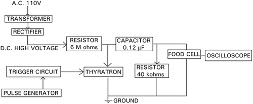
A bench‐top pulsed power treatment system was designed and developed to process fluid products in batch mode.Citation[2] The unit consists of a 30 kV d.c. high voltage pulse generator, a circular parallel plate treatment chamber, and devices for pumping and recording. shows the block diagram of the unit. The 110 V a.c. is raised in voltage through a high voltage transformer, and then rectified. The d.c. high voltage supply then charges up the 0.12 µF capacitor through a series of 6 MΩ resistors. The pulse generator emits a train of 5 V pulses, and the trigger circuit serves to convert that to 500 V pulses using a silicon control rectifier (SCR). The uniquness of this pulsar is that pulses of low‐energy and of instant‐charge‐reversal shape are generated. Conventional pulsar generates pulses of much higher energy and of square or exponential decay shape.
The circular treatment chamber (25.0 cm diameter) has two circular and parallel stainless steel electrodes (16.5 cm diameter). The insulation, Delrin, was constructed to have close physical contact with the electrodes. The distance between the electrodes can be adjusted by inserting Delrin circular plates (14.5 cm diameter) with five different thicknesses: 0.08, 0.16, 0.3, 0.6, or 0.9 cm. Thus, the process volume can be varied between 13.2 and 148.6 mL per batch.
Waveform Measurement
For the batch treatment system, test solutions with three levels of electrical conductivity (tap water at 735 µS/cm, 0.235 wt.% NaCl solution at 5 mS/cm, and 0.47 wt.% NaCl solution at 10 mS/cm) and two levels of electrode gap (0.3 and 0.9 cm) were selected. This created six different load resistances (0.182, 0.364, 0.545, 1.091, 2.474, and 7.421 Ω). The voltage waveforms of each load were recorded at two different voltages (10 and 20 kV) using a digital real‐time storage oscilloscope (model TDS 340, Tektronix Inc., Beaverton, OR) and a high voltage probe (model P6015A, Tektronix Inc., Beaverton, OR). The pulse frequency was fixed at 0.5 Hz in all cases.
Voltage waveforms of the four selected food products (raw whole milk, raw skim milk, fresh orange juice, and fresh apple cider) and two test solutions (tap water and 0.235 wt.% NaCl solution) were also recorded at 15 kV voltage supply and 0.3 cm electrode gap. These were used to verify the circuit and voltage waveform models developed. All waveforms were carefully sampled to avoid aliasing (a false representation of a signal due to insufficient sampling of high frequencies or fast transitions), and each test was repeated atleast three times. Hardcopies of the voltage waveforms were obtained by means of an oscilloscope Polaroid camera (model C‐5C, Tektronix Inc., Beaverton, OR). Quantitative waveform measurements (10 voltage‐time data points for each pulse configuration with three replications) were conducted using the digital cursor system of the oscilloscope.Citation[3] Statistical analyses were performed using the SYSTAT software.Citation[4] A total of 118 voltage waveforms at various electrical conditions and locations of the treatment systems were recorded.
Modeling
The voltage waveforms across the chamber (at load) were modeled as a function of voltage supply, time, and circuit elements (resistor, capacitor, and inductor). EquationEquation 1 shows the general form:
The shaping function was used to represent the dynamic action of the thyratron switch with respect to the load resistance, and can be expressed by two function terms,
The first function term represents the charging action (open switch), and the second function term represents the firing action (close switch). P 10 and P 20 symbolize the amplitude of the pulses, whereas p 1 and p 2 symbolize the time constant of the pulses. These parameters were modeled by simple exponential decay and linear models, as follows:
The measured voltage waveforms were transformedCitation[3] into statistical filesCitation[4] and fitted with EquationEq. 1 using the technique of non‐linear regression modeling: Quasi‐Newton estimation method with 0.10 as parameter starting value, iterations continue until the maximum iteration limit (999) was reached.
Results and Discussion
shows the circuit parameters of the test solutions. With C = 0.12 µF and L = 2 µH (l = 145 cm and r w = 0.25 cm), α and ω were calculated. Shaping function parameters are listed in and . lists the statistical analyses on the model parameters. All the individual voltage waveforms are depicted in to both in terms of load resistance and voltage supply. Similar waveforms were observed for other conditions and solutions. In general, the results indicate a good fit with the data obtained. Statistically, corrected r 2 is in the range of 0.853 to 0.948 for the individual curves. Inaccuracies might have come from missing points on the recorded waveforms due to inconsistency in each triggering and sampling cycle. Errors in the measurements and estimations of circuit parameters (R, L, and C) might also be a cause for low r 2. Results from seem to indicate that there is a good correlation between the individual waveform estimation and the overall model parameters (r 2 = 0.921 to 0.980, p < 0.05). From , the angular frequency (ω) approaches a stable value of 2.04(10−6) rad/s as the load resistance (R) decreases to less than 1 Ω. This is reflected in the model parameters p 1, p 2, and P 20 as well ().
Figure 2. Voltage waveform with 7.42 Ω load resistance and 20 kV voltage applied (o: observed data, – predicted data).
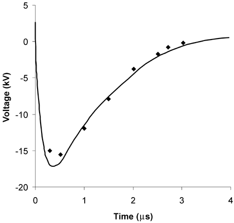
Figure 3. Voltage waveform with 2.47 Ω load resistance and 20 kV voltage applied (o: observed data, – predicted data).
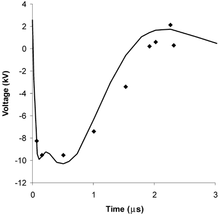
Figure 4. Voltage waveform with 1.09 Ω load resistance and 20 kV voltage applied (o: observed data, – predicted data).
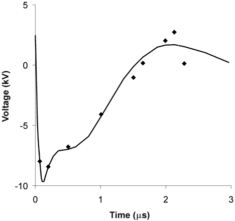
Table 1. Circuit parameters of test solutions using (EquationEq. 1)
Table 2. Overall shaping function parameters of test solutions using (EquationEq. 1)
Table 3. Shaping function parameters of test solutions, expressed in terms of load resistance, using (EquationEq. 1)
Table 4. Statistical analyses on the parameters using (EquationEq. 1)
Since most fluid foods are highly conductive (>2 mS/cm, which yields a load resistance of < 1 Ω), this treatment system can provide a relatively stable pulse configuration (rise time≈50 ns, total pulse width≈2.25 µs, and −ve:+ve peak voltage≈2:1) across the foods if desired. On the other hand, the relative distribution of the pulse width and voltage (the ratio of the −ve to +ve portion of the pulse) would change depending on the load resistance. and show the voltage pulse waveform distribution of the test solutions.
Table 5. Voltage pulse waveform distribution of the test solutions at 10 kV voltage applied
Table 6. Voltage pulse waveform distribution of the test solutions at 20 kV voltage applied
Consider a RCL circuit where the charge, Q c , in the circuit is represented by a simple exponential function,Citation[6] say
The voltage across the resistor (R) can be written as
Voltage waveform of the four selected food products ( raw whole milk, raw skim milk, fresh orange juice, and fresh apple cider) and two test solutions (tap water and 0.235% NaCl) were also taken at 15 kV voltage supply and 0.3 cm electrode distance. Values of α and ω for the foods are shown in . The data on waveforms are sown in . EquationEquation 1 was used for comparison and verification for all solutions and foods. The results are depicted in to for a few products. In general, EquationEq. 1 shows a good approximation with the data obtained, indicating that the model can be used for interpolation (0.2 Ω≤R≤7.4 Ω).
Figure 5. Voltage waveform with whole milk as load resistance and 15 kV voltage applied (o: observed data, – predicted data).
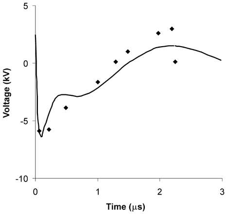
Figure 6. Voltage waveform with whole milk as load resistance and 15 kV voltage applied (o: observed data, – predicted data).
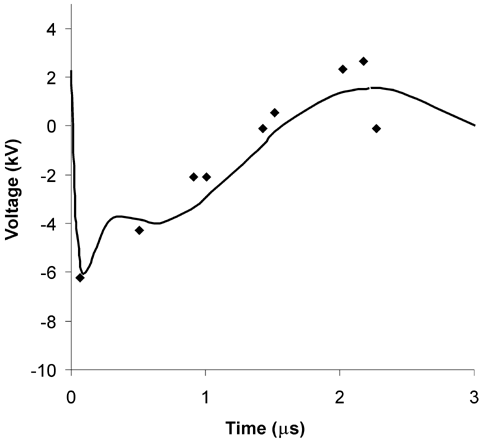
Figure 7. Voltage waveform with whole milk as load resistance and 15 kV voltage applied (o: observed data, – predicted data).
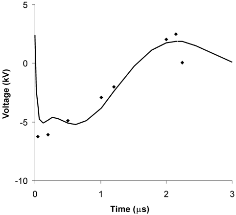
Table 7. Electrical parameters of food products, water, and salt solution
Table 8. Voltage pulse waveform distribution of the products at 15 kV voltage applied
Comparison between the pulse waveforms of whole milk, skim milk, and 0.235% NaCl solution indicate a similar profile. Since all three solutions have similar electrical conductivity (5 ± 0.25 mS/cm), the load resistance (which affects the value of α and ω), and not the physical composition of the food, seems to be an important factor in determining the pulse waveform in this system. Other foods (orange juice, apple cider) also follow the same trend as the solutions tested before, with the 2nd portion of the pulse becoming more and more prominent as the resistance decreases. Yet, the pulse configuration still provides a rise time≈50 ns, total pulse width≈2.25 µs, and −ve:+ve peak voltage≈2:1 across the solutions with R < 1 Ω.
Thus the parameters provided for different conductivity of foods will be useful in predicting the pulse shape. For any food, based on its electrical conductivity, and chamber dimensions and shape, the electrical parameters can be calculated, and then pulse shape can be predicted. This has been demonstrated for milk, orange juice, and apple cider.
The τ, the characteristic time constant (relaxation time) of the cell membrane, is expressed as:Citation[7]
Membrane discharging time ranges from 1 to 10 µs, while 0.1 ms to 2.8 h is needed for membrane recovery.Citation[7] The pulse frequencies used here (0.5 Hz in the batch system and 1–200 Hz in the continuous system) should be able to provide enough time for irreversible membrane rupture (or short enough to prevent membrane recovery), and allow the system to recharge to its full capacity in between pulses.
Conclusions
The voltage waveform across the batch treatment chamber was modeled as a function of voltage applied, time, and circuit elements (resistor, capacitor, and inductor). The shaping function was modeled by simple exponential decay and linear models. Model parameters were obtained from various testing solutions. The model was independently validated by using data from orange juice, apple cider, whole milk, and skim milk.
Experimental data gave a good fit to the model (r 2 = 0.853 to 0.948). The pulse configuration (pulse width, pulse frequency) was compared with the characteristic time constant and the discharging time of a typical intact cell in aqueous suspension. Results indicated that the systems employed should be able to provide enough time for the generation of critical TMP on the cell membrane, for the occurrence of irreversible membrane rupture, and for the system to recharge to its full capacity in between pulses.
References
- Van Devender , J. P. 1992 . Prolong to the special section of pulsed power technology . Proc. IEEE , 80 ( 6 ) : 931 – 933 .
- Ho , S. Y. , Mittal , G. S. , Cross , J. D. and Griffiths , M. W. 1995 . Inactivation of P. fluorescens by high voltage electric pulses . J. Food Sci. , 60 ( 6 ) : 1337 – 1340 .
- 1995 . “ Tektronix Inc. ” . In TDS 340, TDS 360 & TDS 380 Digital Real‐Time Oscilloscopes User Manual 3 17 – 24 .
- 1972 . SYSTAT for Windows, Version 5 Evanston IL , , USA : SYSTAT, Inc. . SYSTAT
- Doebelin , E. O. 1972 . System Dynamics: Modeling and Response 132 Columbus OH , , USA : University of Ohio .
- Giancoli , D. C. 1984 . General Physics 604 – 610 . Englewood Cliffs NJ , , USA : Prentice‐Hall, Inc. .
- Ho , S. Y. and Mittal , G. S. 1996 . Electroporation of cell membrane: a review . Crit. Rev. Biotechnol. , 16 ( 4 ) : 349 – 362 .
- Loew , L. 1993 . “ Electrical properties of biomembranes ” . In Biomembrane: Physical Aspects Edited by: Shinitzkey , M. 341 – 371 . Weinheim , , Germany : VCH .
