
Figures & data
Table 1. An overview of the state-of-art related researches
Table 2. Summary of recent studies in underactuated robot
Figure 1. Principle diagram of robot structure.
Figure 2. Model of inverted pendulum (a) stable position, (b) marginal position, (c) impact position.
Figure 3. The angular trajectory of wheels according to the exchange of legs.
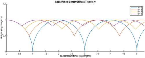
Figure 4. Description for maximum dimensions of obstacle.
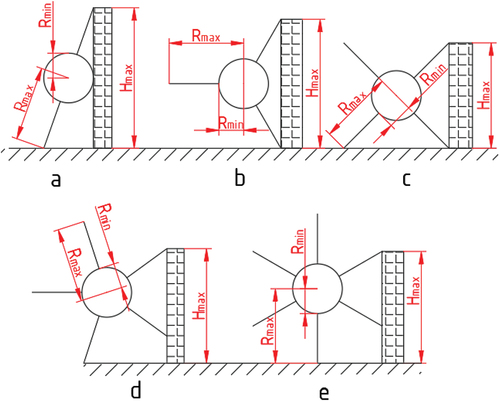
Figure 5. Analysis of forces when moving.
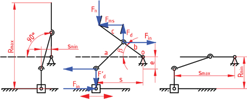
Figure 6. Description for dimensional parameters of wheel.
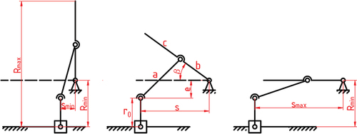
Figure 7. Initial position to move for one-leg contact.
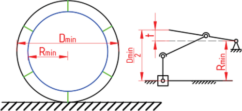
Figure 8. Initial position to move for two-leg contact.
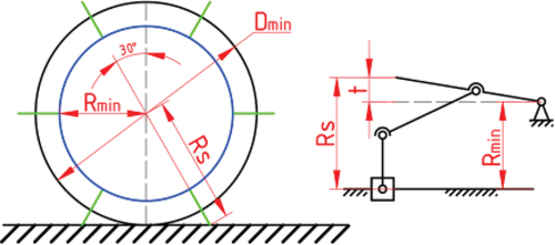
Table 3. List of dimensional values for wheel-legged mechanism
Figure 9. Analysis of forces to overcome the obstacle.
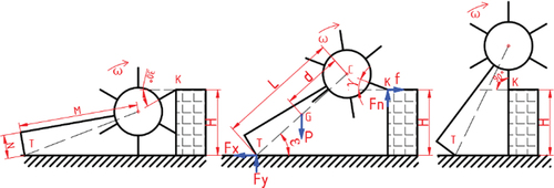
Figure 10. Result of function when overcoming the obstacle with μ = 0,5, μd = 0,4 and H = 97,5 mm.
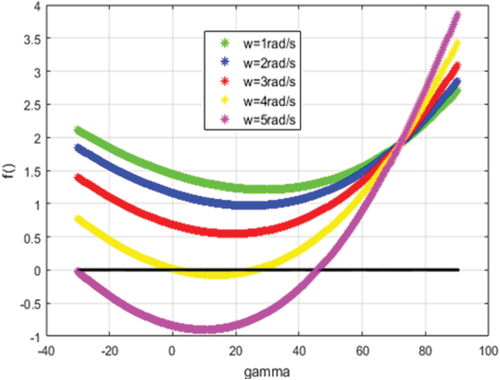
Figure 11. Result of function when overcoming the obstacle with ω = 3,7 rad/s and H = 97,5 mm.
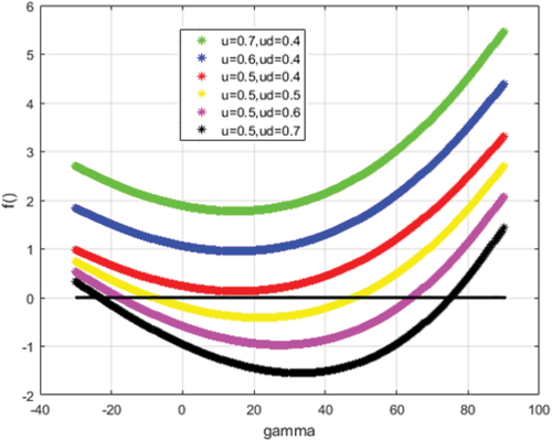
Figure 12. 3D model of hybrid mechanism, (a) component assembly, (b) motion state in wheel mode and (c) motion state in leg mode.
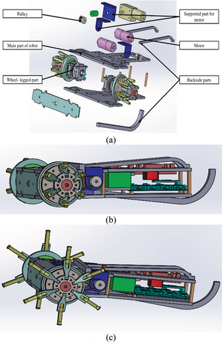
Figure 13. Diagram of electrical connection.
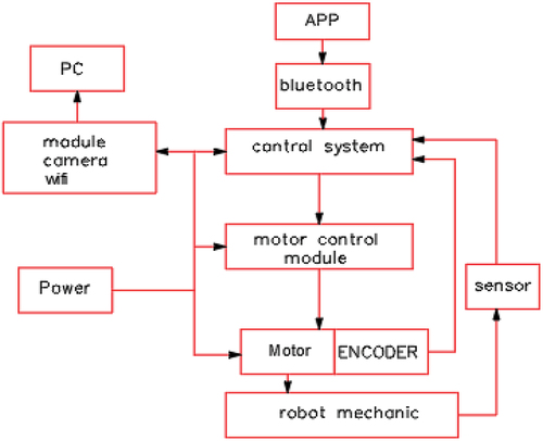
Figure 14. Diagram of hierarchical control in robot system.
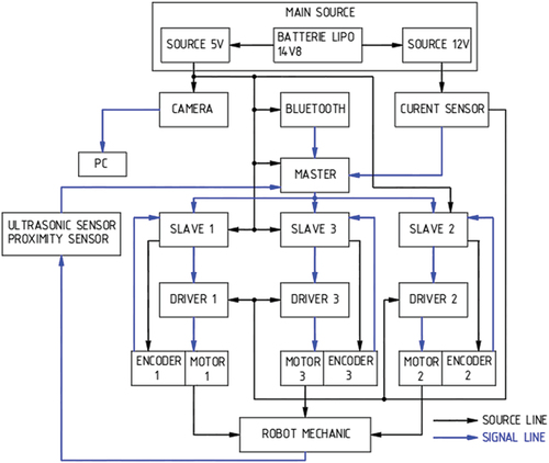
Figure 15. Illustration of kinetic constraints for robot model.
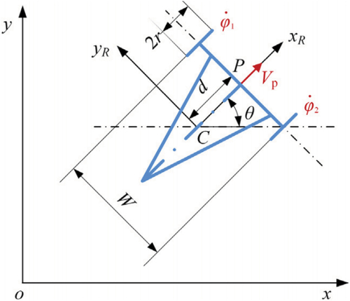
Figure 16. Illustration of various motions for robot model.
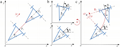
Figure 17. Illustration of path planning using A–star algorithm.
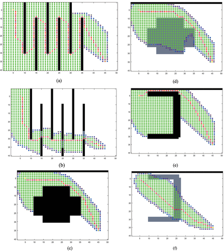
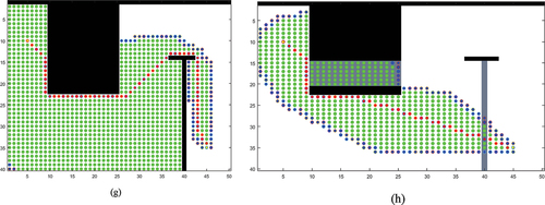
Figure 18. Tracking trajectory using the proposed model.
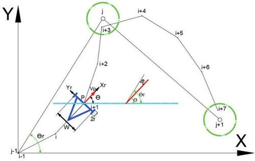
Figure 19. Installation of ultrasonic sensor on robot.
Figure 20. Working map in static context (a) and chaotic one (b).
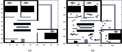
Figure 21. Update obstacles after planning by A–star.
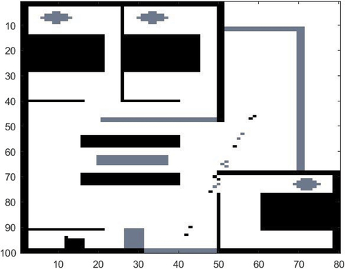
Figure 22. Tracking performance of reference trajectory (dash) and actual trajectory (continuous).
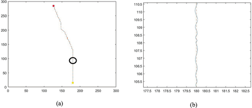
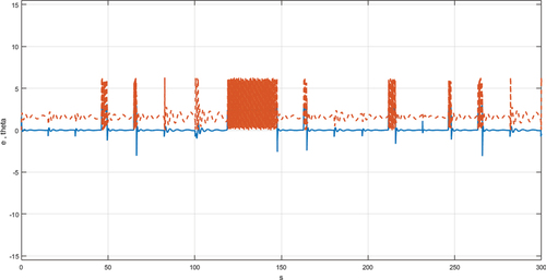
Figure 23. Tracking performance of error (blue) and angle (red).
Table