Abstract
Photovoltaic (PV) panel was used to develop a simple and practical leaf area meter. Components of the developed PV leaf area meter include a PV panel as sensor, a wooden cabinet as enclosure, a flashlight as light source, and a commercial digital multimeter for voltage measurement. The principle of projected area measurement is the voltage generated by the PV panel varies directly with sample area, when corresponding panel surface is exposed to incident radiation. The PV leaf area meter performance was evaluated using cardboard cutouts of various geometrical shapes of known areas and the voltage generated had good correlation (r = 0.9911) with sample areas. Linear fits adequately modeled the areas from non-dimensional voltages (R2 > 0.98). Leaf samples from mango, sapodilla, guava, custard apple, and cotton covering a wide array of natural shapes were tested and compared among the existing graphical, scanner-based electronic leaf area meter, and digital planimeter methods. Digital planimeter produced better performance (R2 = 0.9996) than scanner-based electronic leaf area meter (R2 = 0.9979), followed by the PV leaf area meter linear regression calibration equations based on direct leaf samples (R2 = 0.9953) and leaf samples with glass cover (R2 = 0.9834). However, on testing with additional leaf samples, the glass cover method gave better predictions than direct leaf method. As leaf was flattened by the glass cover and represented the true projected leaf area, this method was recommended. PV leaf area meter costs only 3.9% of scanner-based electronic leaf area meter and 14.7% of digital planimeter. The developed PV leaf area meter had a mode of operation similar to a commercial electronic leaf area meter, yielded quick and reliable results, and was highly cost effective.
INTRODUCTION
Leaves are one of the vital organs of a plant system and the future development of the plant depends mostly upon the persistence of the leaves. Physiologically, leaf performs essential functions such as photosynthesis, respiration, and transpiration for vegetative and reproductive growth of the crop. Sustainability and health of leaves affect crop growth and yield; hence, leaf area measurements assume a great importance in plant growth studies. Measurement of leaf area, a basic physical property, is of value in studies of plant nutrition, plant competition, plant soil-water relations, plant protection measures, crop ecosystems, respiration rate, light reflectance, and heat transfer in heating and cooling processes.[Citation1] Leaf area is also a good indicator of crop yield potential in crops such as tobacco, tea, and green leafy vegetables, where the leaf is the major commercial product.
Reported techniques for leaf area determination include the graphical method, length and width correlation, leaf specific weight correlation, electronic devices, visual or ocular evaluation of detached leaves, contact printing on a light sensitive paper and measuring the area by planimeter, blue printing and optical comparators,[Citation1,Citation2] light interruption method and use of photronic cell,[Citation3] air-flow planimeter,[Citation4] leaf area meters, methods based on computer vision and image processing,[Citation5,Citation6,Citation7] hand scanner linked to microcomputer in combination with developed software,[Citation8] and interactive software for leaf outline tracing with computer mouse.[Citation9]
Computer based leaf area measurement techniques employ image acquisition by camera or scanner with the images subsequently analyzed using specialized image processing software or developed algorithms. Image processing methods can be applied to variety of area measurement situations such as surface area and volume determination of agricultural products,[Citation10] and hydration kinetics of milled rice in hot water based on projected area variation.[Citation11] At present, several brands of desktop and hand held electronic leaf area meters are available commercially. Though the leaf area meters based on computer systems are fast and accurate, they tend to be expensive.[Citation12]
In this study, a simple and practical leaf area meter using a solar photovoltaic (PV) panel was developed and tested. The PV panel utilized was actually meant to charge the battery of a solar lantern. Voltage generated from the PV panel varies directly with the intensity of radiation and the exposed panel area. The variation in voltage generated from the PV panel due to object obstruction of incident radiation varies inversely with of the projected area of the object. Conversely, voltage generated will vary directly when panel surface corresponding to object area is exposed to incident radiation, and this principle is employed in projected area measurement with the PV leaf area meter.
The proposed PV leaf area meter should have an enclosure that houses the PV panel and light source, and a system to measure the voltage from PV panel. The specific requirements of the PV leaf area meter were 1) the enclosure should avoid ambient light entering into the system; 2) the PV panel should be less expensive and sensitive enough to the intended range of area measurement; 3) the light source that should be simple, affordable, readily available, and have fairly constant intensity without fluctuations; 4) the device should allow for quick loading and unloading of samples; and 5) the voltage measuring instrument should be sensitive enough to read the range of voltages expected from PV panel.
Performance of the developed PV leaf area meter can be evaluated by using prepared geometric shapes of known areas. Performance of PV leaf area meter can also be compared with the existing devices such as digital planimeter and scanner-based electronic leaf area meter using leaf samples of selected crops. The following were the specific objectives of this research effort: 1) to develop a leaf area meter using PV panel and determine its performance with geometrical shaped samples of known area and leaf samples of selected crops; 2) to develop a calibration equation estimating leaf areas in terms of measured voltage; and 3) to compare the performance of the developed device with digital planimeter and scanner-based electronic leaf area meter, and to assess the total cost of the device.
MATERIALS AND METHODS
Description of Developed PV Leaf Area Meter
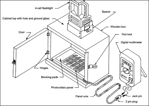
Based on a novel idea of an alternative usage of the PV panel to be the projected area measuring sensor, a PV leaf area meter () was developed and tested,[Citation13,Citation14] keeping in view of the specific design requirements mentioned already. Descriptions and functions of the major components of the PV leaf area meter, namely PV panel, flashlight, and cabinet follow.
PV panel as sensor
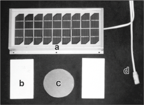
The PV panel (), originally meant for charging a solar lantern battery, was selected as the sensor of the leaf area meter. Overall dimensions of the panel were 276 mm × 130 mm with sensor area of 246 mm × 105 mm (). The panel had 18 PV cell elements arranged in two rows and nine columns. In order to reduce the angle of radiation between the source and the PV panel surface, opaque cardboard pads () blocking two columns on both ends were fixed. These blocking pads expose only the five central columns of 10 PV cell elements thereby ensuring uniform radiation intensity on the panel surface. The effective sensor area available for measurements after applying the blocking pads was 135 mm × 105 mm. Cardboard cutout geometrical samples () of different shapes were used in performance evaluation of the device. From the PV panel the voltage output was drawn through the leads (), and the voltage generated was measured using digital multimeter.
Flashlight as light source
Trial runs with and without voltage stabilization indicated that incandescent electrical light bulbs were unsuitable as light source for the device. The voltages measured from the panel with light bulbs were always fluctuated, more without and less with voltage stabilization, due to the inherent voltage fluctuations of the electrical supply. The continuous up and down variation of radiation intensity from the light bulbs cannot be eliminated unless a steady electricity supply as well as specialized voltage stabilizer was utilized. Efficiency and performance characteristics of the voltage stabilizer were another source of variation in voltage measurement. Furthermore, application of voltage stabilizers also introduces high additional cost to the otherwise intended simple low cost device.
Therefore, a domestic four dry cell flashlight (D type battery) was selected as the light source. Light intensity from the flashlight was almost constant during the short time span required for each measurement. Although the flashlight's light intensity gradually decreased over time, the variation always occurred only in one direction (reduction), unlike the up and down fluctuation of electrical light bulbs. This little variation over time is tackled by non-dimensionalizing the voltage measurements. The flashlight was placed above the top hole of the cabinet () covering the hole completely. A spacer made of sheet metal held the flashlight in a vertical position, since the particular flashlight used cannot stay in vertical position by itself because of its design.
Wooden cabinet as enclosure
A Wooden cabinet with hinged door () enclosed the PV panel. Interior of the cabinet was painted white to maximize the light intensity inside. A circular hole on the top of the cabinet allowed the radiation from the flashlight, and a ground glass panel fitted below the hole made the radiation diffused and uniform. The cabinet was so designed to avoid ambient light entering the cabinet, when the door was closed for measurements. The PV panel lead was passed through a slot, small enough to accommodate the lead but not allow external light.
Theoretical Consideration of Area Measurement
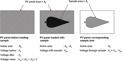
PV panel generates voltages proportional to the exposed area with constant light intensity. When loaded with samples the exposed area is the area complementary to the sample area. The principle of measurement is the voltage generated from PV panel varies directly when panel surface corresponding to object area is exposed to incident radiation. The voltage corresponding to the object area, was derived indirectly from the voltage measurements obtained with and without out the object. The voltage generated by the PV panel corresponding to the area of sample is derived as follows (): Let Ap be the active area of PV panel with the blocking pads when fully exposed. The mean voltage produced was obtained from the voltage with full PV panel exposure to radiation before and after the measurements without samples as:
Samples Preparation
Samples used in the performance evaluation of the PV leaf area meter were the opaque cardboard cutouts of various geometrical shapes of known area. The shapes and sizes of cutout samples and leaf samples selected for performance evaluation and calibration model development were:
-
Circle: Diameter — 10, 20, 30, 40, 50, 60, 70, 80, 90, and 100 mm;
-
Square: Side — 10, 20, 30, 40, 50, 60, 70, 80, 90, and 100 mm;
-
Equilateral triangle: Side — 10, 20, 30, 40, 50, 60, 70, 80, 90, and 100 mm;
-
Rectangle: Length × width — 60 × 20, 80 × 40, 100 × 60, 120 × 80, and 140 mm × 100 mm;
-
Leaf samples (shape): Mango (lanceolate), guava (elliptic), sapodilla (elliptic), and cotton (palmate);[Citation15] and
-
Size: Small, medium, and large.
An ellipse would have been another possible standard shape for cardboard samples. Instead of adding another artificial sample, a wide array of natural shapes from plants was considered. Actual plant leaves with characteristic shapes evaluated with the device included mango (lanceolate — pointed at both ends), guava and sapodilla (elliptic — oval shaped), and cotton (palmate — fingers shaped). These leaf shapes were selected to ensure a wide range of shapes were examined.
Leaf samples were detached from sample plants and three sizes were chosen for each crop considered. Number of repeated measures was five for the geometrical shaped cutouts and three for leaf samples. Leaf samples were tested without (direct samples) and with glass cover, but opaque geometrical cutouts were tested only without glass cover. When glass cover was applied over leaf samples, the leaf was sandwiched between the glass top of PV panel and the glass cover. Testing of device in predicting the leaf area using the developed calibration equations was again carried out with another set of single leaf samples of sapodilla, soap nut (obcordate — heart shaped), guava, custard apple (lanceolate), and mango.
Actual Projected Area of Samples by Existing Methods
Actual areas of geometric shaped samples were evaluated from their standard analytical formulae. Since leaf shapes were irregular, leaf areas were evaluated by graphical method and digital roller planimeter (Model: PLACOM; KP90N, Tokyo, Japan) method as described elsewhere.[Citation9] The graphical method was considered as the reference method, and its measurements were used to evaluate other methods as well as the developed models. Leaf areas were also measured for comparison using a scanner-based electronic leaf area meter (Model MK2; Delta-T Devices, Cambridge, UK).
Procedure of Area Measurement using PV Leaf Area Meter
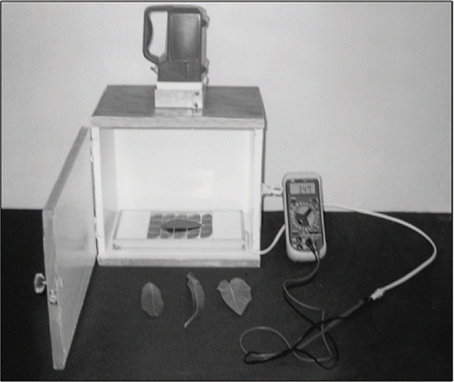
The developed leaf area meter was connected to a digital multimeter for voltage measurements (). A maximum voltage selection of 20 V on multimeter was found suitable. With the cabinet door closed, a gradual reduction of voltage was observed soon after the flashlight was switched on. A relative stabilization in measured voltage set in rapidly thereafter. The stabilized voltage before loading the sample (Vb ), with the complete PV panel area exposed (with blocking pads), was recorded. Then the sample was loaded by placing it centrally on the PV panel and the observed stable voltage (Vps ) was recorded. After removing the sample, the stabilized voltage from the complete PV panel area (Va ) was again recorded. Since some leaf surfaces are curved, flattening was required to obtain the proper projected area. Measurements were carried out without and with glass cover to compare the methods. Gentle flattening of leaf samples was accomplished using a transparent glass cover with dimensions similar to the glass sheet of the PV panel. Flattening effect of the glass cover on leaves facilitated the presentation of their true projected area.
Throughout the three voltage measurements (Vb , Vps , and Va ), the flashlight was switched on, as this ensured stabilized voltage readings. The time involved for a set of measurements with a sample never went beyond 90 s. For all samples and repeated measures, the same procedure was followed.
Data Analysis
Variation of observed non-dimensional voltages with the actual area of samples, and prediction of sample areas from observed voltages were modeled by studying the nature of variation. Suitable calibration models were fitted by regression procedure and relevant statistics were evaluated using SAS.[Citation16] Specific models based on geometrical shapes and combined model as well covering all shapes were developed, and their performances were studied. Performances comparisons of digital planimeter, electronic leaf area meter, and calibration equations of PV leaf area meter in area prediction were also made with the graphical method.
RESULTS AND DISCUSSION
Voltage Variation of Geometrical Shaped Samples
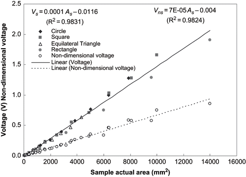
Voltages (EquationEq. 2) and the non-dimensional voltages (EquationEq. 3) produced by the PV panel through the samples of various geometrical samples correlated well with the actual areas (). Pearson correlation coefficients of observed voltages (r = 0.9915) and non-dimensional voltages (r = 0.9911) with actual areas of geometrical samples showed a strong positive correlation. Hence, the simplest linear fit selected to model Vs (Vs = 0.0001 As – 0.0116; R2 = 0.9831) and Vns (Vns = 7E-05 As – 0.004; R2 = 0.9824) from As gave good performances ().
Linear Prediction Models of Geometrical Shaped Samples
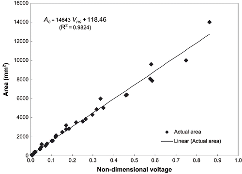
Since non-dimensional voltages were well correlated to areas of geometrical samples, a combined linear model of was fitted to predict areas of geometrical samples ():
Performance of the combined prediction model (EquationEq. 4) in terms of observed difference (mm2) and deviation (%) showed that the smaller the sample area the larger the variation, irrespective of shapes () and the prediction improved greatly when the area was larger than approximately 100 mm2.
Table 1 Actual and linear model predicted areas of geometrical samples
Multiple ANOVA based on sample shape area means () revealed that the effect of shapes on area were significantly different (P < 0.05). Statistically at P < 0.05, rectangle belonged to one group, with circle and equilateral triangle belonged to another group, but square belonged to both groups. Following are the individual prediction models based object shapes:
-
Circle:As = 13425 Vns + 191.2 (F = 2986; R2 = 0.9973);
-
Square:As = 13390 Vns + 248.1 (F = 2392; R2 = 0.9967);
-
Equilateral triangle: As = 15162 Vns + 48.5(F = 1014; R2 = 0.9922); and
-
Rectangle:As = 15730 Vns + 496.3 (F = 4620; R2 = 0.9994).
Although the individual prediction models based on shapes offered slight improvement in prediction, the combined prediction model (EquationEq. 4) offered comparable performance and had the advantage of independent of object shapes. However, individual prediction models are recommended for accurate predictions of practical measurements with leaf samples.
An attempt was also made to study the performance of second order polynomial combined prediction model of geometrical samples.
The second order polynomial prediction model offered no further improvement in performance over the linear combined prediction model; hence, the simple linear equation, such as EquationEq. (4) can be used to calibrate the device for all practical purposes.
Leaf Area Measurement using Existing Methods and PV Leaf Area Meter
With graphical method considered as the reference (), the digital planimeter performed better (absolute mean deviation (AMD) of 0.58 ± 0.90%; R2 = 0.9996) than electronic leaf area meter (AMD = 1.89 ± 2.1%; R2 = 0.9979) in area determination. Low resolution of the particular electronic leaf area meter, having an accuracy of only 100 mm2, may be the reason for the observed deviation.
Table 2 Measured and model predicted leaf areas using different methods
Calibration Models of Leaf Area Measurement using PV Leaf Area Meter
The fitted calibration models with direct leaf samples and leaf samples with glass cover using the exclusive leaves data are:
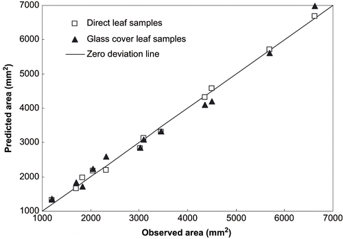
Calibration models of direct samples (AMD = 4.04 ± 3.28%; R2 = 0.9953) performed better than that of samples with glass cover (AMD = 6.52 ± 3.70%; R2 = 0.9834) with respect to the graphical method (). Although measurements with direct leaf samples compared well with graphical method (), the flattening effect of glass cover on leaf represented the true projected leaf area and accounted for the varying leaves natural surface curvature. Based on EquationEq. (6) and EquationEq. (7) and results (), the predictions of glass cover sample models tend to be a little larger than the direct leaf sample model, as the mean non-dimensional voltages for direct samples (0.171 ± 0.095 V) and glass cover sample (0.167 ± 0.093 V) were not much different. The additional glass cover might have reflected away some of the radiation from the light source, which might otherwise have reached the PV elements and produced the voltage. Flattening of leaf samples might have recovered the area involved in leaf surface curvature, in turn producing larger area prediction. This feature may be the reason for observed increased deviation of glass cover method. However, the predictions of both the methods were comparable ().
Measurements with glass cover on leaf samples tend to be more repeatable as the projected area of a flattened leaf was always be the same than the direct leaf samples. In the case of direct leaf samples, the leaf surface curvature cannot be controlled. Therefore, use of a glass cover over leaf samples on PV panel senor is recommended from this study.
Testing of PV Leaf Area Meter and Leaf Area Predictions
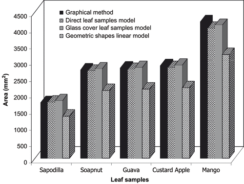
Further testing of the developed PV leaf area meter was carried out with additional leaf samples and the predictions were made using the previously developed direct sample model (EquationEq. 6), glass cover model (EquationEq. 7), and geometric samples combined linear model (EquationEq. 4). The glass cover leaf samples model gave the best prediction (AMD = 1.69 ± 1.45%; R2 = 0.9944) followed closely by direct leaf samples model (AMD = 2.13 ± 1.58%; R2 = 0.9850), and the geometric samples model produced the largest deviation (AMD = 23.78 ± 0.59%; R2 = 0.2164), with reference to the graphical method ().
The possible source of increased deviations of the geometric samples model (EquationEq. 4) was due to the difference in the transmittance of the cardboard cutouts and leaf samples. Cardboard cutouts being opaque would have completely blocked the radiation reaching the PV panel, but the leaf samples being translucent would have allowed some radiation. Hence, the calibration model based on opaque samples will have some performance issues while predicting areas of translucent leaves. The geometric samples model was tested for comparison purpose only, and was not recommended for leaf area predictions, as the transmittance of the cardboard cutouts and leaf samples, and the usage of glass cover in measurement was different for these samples.
Even though the transmittance of leaves varies with crop species and maturity, proper calibration model development with specific leaf samples addresses the variability. Prediction performance of the device can be improved by developing calibration models specific to different crop species and maturity levels. Calibration procedure for specific type of samples can be viewed as the routine calibration procedure involved with most of the standard measuring instruments. However, a single calibration model developed based on several crops, such as EquationEq. (6), can also be used for quick rough estimates. On the instrument side, the measurement accuracy can be greatly improved by employing modern high-sensitive PV panels with more cell density in a module. The developed PV leaf area meter yielded quick and reliable results, and its mode of operation is similar to a commercial electronic leaf area meter.
Cost Estimation of the Developed PV Leaf Area Meter
Based on 2001 price information and assuming a conversion of 45.00 rupees to 1.00 dollar, the cost estimates of various components were: PV panel = $30.0; digital multimeter = $57.78; flashlight with cells = $5.56; complete material cost of painted wooden enclosure with ground glass and glass cover on PV panel = $9.56; fabrication expenses = $4.44. Therefore, the total cost estimate of the PV leaf area meter was $108.0. Cost estimates were based on the fabrication scenario encountered in India. Potential costs in different geographic and economic situations may vary.
On comparing the costs of existing instruments used in the study, the PV leaf area meter with digital multimeter complete costs only 3.9% (25.7 times less) of the scanner-based electronic leaf area meter price and 14.7% (6.8 times less) of the digital planimeter price. Cost of the device excluding the digital multimeter was $50.0 only. This means the digital multimeter, a standard laboratory instrument, covered 53.5% cost of the complete device. Therefore, the cost of the complete device can be greatly reduced when a multimeter is already available or a simpler voltmeter with required accuracy is used instead of the expensive multifunction digital multimeter. Price comparison with existing devices makes the PV leaf area meter highly cost effective.
CONCLUSIONS
Usage of the solar photovoltaic (PV) panel as a sensor to measure areas of planar objects was demonstrated and a leaf area meter using solar PV panel was successfully developed and tested. Linear relationship adequately modeled the sample areas from the corresponding non-dimensionalized voltages from PV panel. With reference to the graphical method, the digital planimeter produced the best performance (absolute mean deviation (AMD) = 0.58%) followed by the scanner-based electronic leaf area meter (AMD = 1.89%), PV leaf area meter direct leaf samples calibration model (AMD = 4.04%), and glass cover leaf samples calibration model (AMD = 6.52%). On further testing the calibration models with additional leaf samples, the glass cover leaf samples model (AMD = 1.69%) performed better than direct leaf sample model (AMD = 2.13%). Therefore, glass cover utilization and corresponding calibration model are recommended for leaf area measurement with the developed PV leaf area meter. The developed PV leaf area meter is highly cost effective when compared to the scanner-based electronic leaf area meter (25.7 times less) and the digital planimeter (6.8 times less) costs. Cost of the PV leaf area meter can be further reduced by using a simple voltmeter having adequate accuracy instead of a multifunction digital multimeter. Performance of the PV leaf area meter can be further enhanced by the application of high-sensitive PV panels with more cell density as well as by calibration model development specific to crop species and maturity levels of leaves.
REFERENCES
- Mohsenin , N.N. 1986 . Physical Properties of Plant and Animal Materials , 107 – 110 . New York : Gordon and Breach Science Publishers Inc .
- Marshall , J.K. 1968 . Methods for Leaf Area Measurement of Large and Small Leaf Samples . Photosynthetica , 2 : 41 – 47 .
- Miller , E.E. , Sadbolt , C.A. and Holm , L. 1956 . Use of an Optical Planimeter for Measuring Leaf Area . Plant Physiology , 31 ( 6 ) : 484 – 486 .
- Jenkins , H.V. 1956 . Air Flow Planimeter for Measuring the Area of Detached Leaves . Plant Physiology , 35 ( 5 ) : 532
- Trooien , T.P. and Heermann , D.F. 1992 . Measurement and Simulation of Potato Leaf Area Using Image Processing: III. Measurement . Transactions of the ASAE , 35 ( 5 ) : 1719 – 1721 .
- Nyakwende , E. , Paull , C.J. and Atherton , J.G. 1997 . Non–destructive Determination of Leaf Area in Tomato Plants Using Image Processing . Journal of Horticultural Science , 72 ( 2 ) : 255 – 262 .
- Chien , C.F. and Lin , T.T. 2002 . Leaf Area Measurement of Selected Vegetable Seedlings Using Elliptical Hough Transform . Transactions of the ASAE , 45 ( 5 ) : 1669 – 1677 .
- Caldas , L.S. , Bravo , C. , Piccolo , H. and Faria , C.R.S.M. 1992 . Measurement of Leaf Area with a Hand-scanner Linked to a Microcomputer . Revista Brasileira de Fisiologia Vegetal , 4 ( 1 ) : 17 – 20 .
- Igathinathane , C. , Prakash , V.S.S. , Padma , U. , Ravi Babu , G. and Womac , A.R. 2006 . Interactive Computer Software Development for Leaf Area Measurement . Computers and Electronics in Agriculture , 51 ( 1–2 ) : 1 – 16 .
- Sabliov , C.M. , Boldor , D. , Keener , K.M. and Farkas , B.E. 2002 . Image Processing Method to Determine Surface Area and Volume of Axi-symmetric Agricultural Products . International Journal of Food Properties , 5 ( 3 ) : 641 – 653 .
- Ramesh , M.N. 2001 . An Application of Image Analysis for the Study of Kinetics of Hydration of Milled Rice in Hot Water . International Journal of Food Properties , 4 ( 2 ) : 271 – 284 .
- O'Neal , M.E. , Landis , D.A. and Isaacs , R. 2002 . An Inexpensive, Accurate Method for Measuring Leaf Area and Defoliation through Digital Image Analysis . Journal of Economic Entomology , 95 ( 6 ) : 1190 – 1194 .
- Chennakesavulu , B. and Manohar , K. 2001 . “ On the design and development of photovoltaic leaf area meter, Unpublished undergraduate thesis, College of Agricultural Engineering ” . Bapatla, , India : ANGRAU .
- Igathinathane , C. , Chennakesavulu , B. , Manohar , K. , Womac , A.R. and Pordesimo , L.O. Leaf Area Meter Development Using Photovoltaic Panel and Testing . ASABE Paper No. 066078 . 2006 .
- Wikipedia, The free encyclopedia. Image:Leaf morphology no title.png http://upload.wikimedia.org/wikipedia/commons/5/51/Leaf_morphology_no_title.png (Accessed: 8 August 2006 ).
- SAS Institute . 2004 . The SAS System for Windows , Version 9.1.3 , Cary, North Carolina : SAS Institute, Inc .
