
 ?Mathematical formulae have been encoded as MathML and are displayed in this HTML version using MathJax in order to improve their display. Uncheck the box to turn MathJax off. This feature requires Javascript. Click on a formula to zoom.
ABSTRACT
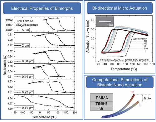
The martensitic phase transformation in Ti40.4Ni48Hf11.6 shape memory alloys is leveraged for bi-directional actuation with TiNiHf/SiO2/Si composites. The shape memory properties of magnetron sputtered Ti40.4Ni48Hf11.6 films annealed at 635°C – 5 min are influenced by film thickness and the underlying substrate. Decreasing TiNiHf film thickness from 21 μm to 110 nm results in the reduction of all characteristic transformation temperatures until a critical thickness is reached. Particularly, Ti40.4Ni48Hf11.6 thin films as low as 220 nm show transformations above room temperature when deposited on SiO2 buffer layer, which is of great interest in nano-actuation. In comparison, 220 nm films on Si substrates are austenitic at room temperature, and thus not suitable for actuation. Thermal fatigue tests on TiNiHf/SiO2/Si bimorphs demonstrate better functional fatigue characteristics than freestanding films, with an average reduction of 15°C after 125 cycles, with temperature stabilization subsequently. Experimental bi-directional actuation results are promising in the development of bistable actuators within a PMMA/TiNiHf/Si trimorph composite, whereby the additional PMMA layer undergoes a glass transition at 105°C. With the aid of constitutive modeling, a route is elaborated on how bistable actuation can be achieved at micro- to nanoscales by showing favorable thickness combinations of PMMA/TiNiHf/Si composite.
Graphical abstract
1. Introduction
Next-generation of silicon (Si)-based nanophotonic and nanomechanical devices, such as optical waveguide switches and routers in advanced communication technology, demand for ultra-small (micro and nano) actuators allowing for large displacements compared to their footprint size [Citation1]. In particular, bi-directional and bistable actuators that could be directly integrated onto Si chips are attractive for such applications [Citation2]. Actuators based on sputtered thin-film NiTiX (X = Zr, Hf, Pd, Cu, Pt, Au) shape memory alloys (SMAs) have the largest power-to-weight ratio among lightweight technologies. SMA actuators are known to exhibit limited speed. However, heat transfer scales favorably with downscaling allowing for an increase of actuation frequency. At the nanoscale, frequencies may reach the kilohertz regime depending on the heat transfer rate and fraction of transforming SMA material [Citation3]. This investigation focuses on a route for design and fabrication of quasi-stationary bi-directional and bistable switching devices with large stroke and force that could be scaled down to nanometer dimensions, which may not be achieved by other technologies. Sputtered TiNiHf SMAs are attractive for this investigation because they are low in cost, have large transformation temperatures, and offer high work density among various SMAs [Citation4–6]. SMA/Si bimorph nano-actuators have been fabricated using standard E-beam lithography, wet etching, and micro-machining with conventional plasma etching techniques (e.g. RIE, IBE) [Citation7–10]. These bimorph actuators take advantage of the combined bimorph and shape memory effect, which arises when SMAs are sputtered on a substrate with a different coefficient of thermal expansion (CTE) [Citation8–10]. In the case of this work, this is between the substrate, silicon (αSi = 2.6 10–6 K−1) [Citation11], and the two different crystallographic phases of TiNiHf (cubic and monoclinic), which are dependent on atomic composition. For example, for a TiNiHf20 alloy, austenite’s CTE is αA = 49
10−6 K−1 and the isotropic polycrystalline CTE value for martensite phase is calculated to be αM = 9.5
10−6 K−1 [Citation12,Citation13]. Another advantage of TiNiHf/Si bimorph actuators is the prospect of developing bistable actuation by adding a third layer of polymer with a glass transition temperature (Tg) that falls in between the martensite and austenite phase transformation temperatures of the SMA [Citation14–16]. Alternatively, bistable actuation can be achieved by adding an SMA with a narrow hysteresis (e.g. TiNiCu) as the third layer [Citation9,Citation17,Citation18].
Controlling actuation precisely with Ni-lean TiNiHf is challenging compared to other SMAs like Ni-rich TiNiHf, NiTi, and TiNiCu, as they suffer from lower transformation strains [Citation6], have unstable transformation temperatures with thermal cycling [Citation19], and have a low strength against dislocation plasticity [Citation20]. Furthermore, the large thermal hysteresis reflects poor crystallographic compatibility between the martensite and austenite phases [Citation21,Citation22], which is known to lead to unwanted effects such as structural/functional fatigue, and a change in volume during the phase transformation, known as the volume effect [Citation12]. The larger thermal hysteresis is detrimental to the lifetime and energy efficiency of TiNiHf devices [Citation23]. These problems may be overcome by training TiNiHf SMAs [Citation24,Citation25], aging Ni-rich NiTiHf compositions [Citation20,Citation21,Citation26,Citation27], or by designing TiNiHf-based layered bi-/multimorph composites [Citation28]. The functional and structural fatigue properties in TiNiHf can be controlled by composition and microstructure (grain size, precipitate size, precipitate homogeneity), which is dependent on annealing conditions [Citation4,Citation19]. Even though Ni-lean TiNiHf alloys are claimed to have poor functional stability, previously Bechtold et al. [Citation23] showed that 20 μm–25 μm thick Ni49.2Ti31.4Hf19.3 films can undergo a phase transformation for an average of 1.5 × 10⁶ actuation cycles when tested to a maximum critical stress of 300 MPa. However, when the maximum critical stress was increased to 450 MPa, the number of cycles until failure was reduced to an average of 65 K. Improved fatigue in these sputtered Ni-lean TiNiHf alloy samples could be due to small grain size (~100 nm) and finely dispersed small precipitates at the grain boundaries [Citation23]. Another advantage of Ni-lean TiNiHf alloys is that they can be heat treated at moderate temperatures for a short amount of time to generate fine, homogeneous distributions of coherent zone structures and Ti2 Ni-type precipitates, which can strengthen the lattice against slip [Citation4,Citation29].
Film thickness effects on the transformation temperatures of TiNiHf/Si bimorphs must be taken into account when designing TiNiHf actuators. This is specifically of interest for bistable nano-actuators because the SMA transformation temperatures need to be coupled to the transition temperatures of the third layer (e.g. polymer, additional SMA). Decreasing SMA film thickness from micro- to nanoscale is known to decrease the martensitic transformation temperatures for several SMA systems [Citation30–32]. Sputtered TiNiHf thin films are also reported to have lower transformation temperatures compared to bulk material of similar compositions, attributed possibly to be due to finer grain structures [Citation29]. Several studies explore the properties of bulk TiNiHf [Citation33–36], freestanding TiNiHf films [Citation23], TiNiHf films on Mo substrates [Citation9,Citation37], and TiNiHf films on silicon substrates [Citation24,Citation29,Citation38]; however, there are only a few studies that show the properties of sputtered TiNiHf films on silicon oxide (SiO2) buffer layers on Si substrates [Citation4].
In this work, thickness effects and functional fatigue characteristics are investigated in freestanding TiNiHf films (21 µm – 5 µm) and films 5 µm down to 110 nm on Si substrates with and without SiO2 buffer layers. The influence of film thickness on the transition temperatures of TiNiHf/Si and TiNiHf/SiO2/Si bimorphs is compared, and limits for downscaling to a scale usable for nanodevices are discussed. The possibilities of downscaling and tailoring the properties make TiNiHf a promising material in the development of bistable nano-actuators with an additional PMMA layer to the bimorph. A thermomechanically coupled finite element model is also implemented to guide the design of favorable thickness combinations of the PMMA/TiNiHf/Si composite layers to achieve such bistable nano-actuators.
2. Methods and materials
2.1 Preparation of freestanding TiNiHf films
Structured freestanding amorphous Ti40.4Ni48Hf11.6 films were fabricated into dogbone geometries through a combination of UV-lithography, DC magnetron sputtering, and a wet chemical etching process, as described in detail by Lima de Miranda et al. [Citation39]. A Von Ardenne CS730S (Von Ardenne, Germany, base pressure < mbar) cluster magnetron sputtering device was used to sputter amorphous Ti40.4Ni48Hf11.6 films onto a pre-structured substrate using a multilayer sputter deposition approach. A 4-inch Ti42Ni43Hf15 target (Ingpuls, Germany) was sputtered for 35 s (deposition layer thickness of ~57 nm, pressure of
mbar, argon flow of 25 sccm, and power of 150 W). Next, an 8-inch pure Ti target was sputtered for 10 s (deposition layer thickness of ~10 nm, pressure of
mbar, argon flow of 25 sccm, power of 100 W). By repeating this multilayer deposition sequence, amorphous freestanding Ti/TiNiHf films were sputtered with varying thickness (5 ± 0.5 μm, 10 ± 1 μm, and 21 ± 2 μm). Due to the sputter yield, films are typically 10–15% thinner at the edge of a 4-inch wafer compared to the center. Rapid thermal annealing (Createc Fischer RTA-6 SY09, Germany) was used to crystallize the amorphous films and homogenize the microstructure. Different RTA temperatures between 635°C and 750°C and times between 5 min and 60 min were tested before selecting on the final heat treatment for all samples of 635°C – 5 min.
The nominal film composition was determined using a Helios NanoLab 600 scanning electron microscopy (SEM) (FEI, Germany) equipped with an energy-dispersive X-ray spectroscopy (EDX) silicon drift detector (Oxford Instruments, UK). Qualitative analysis used Ti49.60Ni50.40 binary standard; however, the error on all reported compositional data is around ± 0.5 at.%. EDX measurements were taken for sputtered amorphous TiNiHf film on a 100 mm silicon substrate. The average film composition was determined to be Ti40.4Ni48Hf11.6 for all samples. Slight compositional variations are expected to be sources of error in the following experiments.
2.2 Preparation of TiNiHf/Si and TiNiHf/SiO2/Si bimorphs
TiNiHf/Si and TiNiHf/SiO2/Si bimorph structures were prepared using the same multilayer sputter approach described above onto chips with lateral dimensions of 20 mm × 20 mm. Amorphous Ti40.4Ni48Hf11.6 films of different thicknesses (5 ± 0.5 μm, 2 ± 0.2 μm, 0.88 ± 0.08 μm, 0.44 ± 0.04 μm, 0.22 ± 0.02 μm, and 0.11 ± 0.01 μm) were deposited and annealed on 525 ± 20 μm (100) silicon substrates (Siegert Wafer, Germany) and 1.5 μm SiO2/525 ± 25 μm (100) silicon substrates (MicroChemicals, Germany). TiNiHf films on SiO2/Si substrates are ~10% thicker than the films on Si substrates because the SiO2/Si substrates were sputtered in the direct center of the device, while the pure Si substrates were sputtered adjacent to the SiO2/Si sample. TiNiHf films with two different thicknesses (2 ±0.1 μm and 0.88 ±0.04 μm) were also sputtered onto 100 nm SiO2/ 300 ±3 μm (100) Si substrates (Si-mat silicon, Germany), pre-structured into cantilevers (3.5 mm x 20 mm) for bi-directional actuation measurements. All film composites were annealed via RTA at 635°C – 5 min.
2.3 Tensile testing
The mechanical properties of TiNiHf films were determined using a high-temperature tensile test on freestanding TiNiHf films. The dogbone geometry has been chosen with a width and length of 500 µm and 4 mm, respectively. The tensile tests were conducted using a displacement-controlled micro-tensile setup equipped with a load cell (KM26z-0.2kN, ME measuring systems) for force measurements and a digital camera (Pike 505, Allied Vision Technology) to record images for measurement of corresponding strain values using non-contact digital image correlation method. The cross-correlation of images with speckle patterns is evaluated using MATLAB code.
2.4 Differential scanning calorimetry (DSC)
Thermal analysis and thermal cycling on freestanding SMA films (thickness of 5 μm, 10 μm, 21 μm) were conducted on a DSC 204 F1 Phoenix (Netzsch, Germany) with a heating and cooling rate of 10 °Cmin−1. The transformation temperatures and latent heat of the SMA are determined using the software Proteus 7.1.0 by the tangent method. Thermal hysteresis is calculated according to , where
/
correspond to austenite start and finish temperatures and
/
correspond to martensite start and finish temperatures.
2.5 Electrical resistance measurements
Four-point resistance measurements were carried out inside a cryostat to determine the temperature-dependent electrical resistance of TiNiHf films constrained by Si and SiO2/Si substrates. Quasi-stationary conditions guaranteed that influence of temperature change is negligible during measurement. For films of micrometer thickness, probes contacting the film surface were used to connect to the setup, and for films of nanometer thickness, films were connected by wire bonding. Phase transformations were determined by change in resistance with temperature, and transformation temperatures were calculated using the tangent method.
2.6 X-Ray Diffraction (XRD)
The martensitic crystal structures and transformation temperatures of TiNiHf films on Si and SiO2/Si substrates were confirmed using temperature-dependent XRD with a SmartLab 9 kW diffractometer (Rigaku, Japan), CuKα radiation (λ = 1.5406 Å), and 2-D Hypix3000 detector operated in 1D mode. θ-2θ scans in the range of 10–100° were conducted with a step size of 0.02° and a scan speed of 20°/min. A heating stage (AntonPaar DHS 1100, Germany) and cooling stage (AntonPaar DCS 350, Germany) was used in the temperature range between –100 °C and 130 °C.
2.7 Cantilever deflection measurements
Functional fatigue behavior in bi-directional actuators was characterized by measuring cantilever deflection as a function of temperature. The cantilever deflection measurement setup contains a laser, a mirror for directing the laser onto the surface, a position-sensitive detector (PSD) to detect deflection, a Peltier element for heating and cooling, and a thermocouple.
The actuator’s stroke, , of a cantilever can be calculated using EquationEquation (1)
(1)
(1) :
where corresponds to laser dislocation on the PSD surface,
is length of the cantilever beam,
is the distance between cantilever tip and PSD (
= 117 mm), and deflection is measured as volts on the PSD (V) which is converted to displacement (mm) by using a factor dx/dU = 0.794 mm/V. Each cantilever has a size of 3.5 mm × 20 mm, with a freestanding cantilever length of 14 mm. The experiments were performed under vacuum (10−4 mbar) for each sample with a 10°C/min heating/cooling rate within a temperature range of 30°C–170°C.
2.8 Constitutive modeling
The model used to describe the SMA is in line with the model by Sedlak et al. [Citation40], extended to the finite strain case with inhomogeneous temperature fields. The model details regarding numerical procedures are given in [Citation41]. In contrast to other phenomenological finite strain SMA models, it makes use of a projection method to satisfy the inelastic volume preservation constraint [Citation42,Citation43]. Further, we assume a multiplicative split of the deformation gradient in the form of , where
is the elastic,
the inelastic, and
the thermal part of the deformation gradient
. Moreover, the volume fraction of martensite
and the inelastic right Cauchy–Green tensor
are used as the internal variables of the model at hand. Additionally, the model is implemented into the framework of generalized standard materials [Citation44], which ensures thermodynamic consistency when carefully choosing the potentials. This framework is then extended to non-constant temperatures
using a variational formulation [Citation45].
Thus, the total potential is given by , where
is the rate of the Helmholtz free energy density and
is the dissipation potential. This potential is integrated into the system and minimized to solve the energy balance as well as the linear momentum balance in the bodies considered. We assume
to be the sum of an elastic, a chemical, and a hardening-type energy. The elastic energy is given by
where and
are the Lamé parameters determined by a Reuss-like rule of mixture and
is the determinant of
. Further, the Kirchhoff stress
is given by
, where
is the elastic left Cauchy–Green tensor. For the chemical energy, we assume a standard relationship [Citation46,Citation47]:
with the volume-specific internal energy of the austenite phase , the specific entropy of the austenite phase
, the specific heat capacity
, the difference in specific entropy of the austenite and martensite phase
, the equilibrium temperature
, and the absolute temperature
. Since the inelastic strains vanish with
, the inelastic strain
is assumed to be given by
, where
is a measure for the effective transformation strain in twinned regions. Additionally, the hardening-type energy is given by (compare to Sedlak et al. [Citation40])
where is the maximum transformation strain and
and
are hardening parameters. The thermal strains and jump in volume between martensite and austenite cells are modeled by
with the thermal strain
where are the coefficients of thermal expansion and
are the reference temperatures of austenite and martensite. To model the inelastic behavior, we define the dissipation potential, depending on the direction of the transformation, to be
where is the symmetric part of the inelastic ‘velocity gradient,’
with
and
the stress at which reorientation occurs. Furthermore, the heat conduction is assumed to follow Fourier’s law with thermal conductivity
. After further numerical treatment of the volume preservation constraint and differentiability problems of the dissipation potential, we solve the problem using an active set algorithm, which is embedded into the finite element analysis software FEAP [Citation48]. The material parameters employed are given in Table S1 (in the Supporting Information).
3. Results
3.1 Functional properties of freestanding TiNiHf films
3.1.1 Thermal fatigue evaluation
The characteristic martensitic phase transformation temperatures, austenite start (), austenite finish (
), martensite start (
), martensite finish (
), and latent heat of transformation of forward (
) and reverse transformations (
) are determined by DSC. ) shows the first DSC cycle of 21 µm, 10 µm, and 5 µm thick freestanding films depicting a reduction in all characteristic transformation temperatures, with decreasing film thickness. The thermal transformation temperatures, latent heat, and thermal hysteresis (
) are given for all samples in . Only a minor influence on thermal hysteresis is noticeable with a reduction in TiNiHf film thickness from 21 μm to 5 μm. However, the transition temperatures, latent heat of transformation, and thermal hysteresis width of TiNiHf films can also be slightly increased by annealing the films at a higher temperature as shown in our previous work [Citation49].
Figure 1. (a) First DSC cycle showing Ni47.7Ti40.7Hf11.6 freestanding films annealed at 635°C – 5 min with decreasing film thickness from 21 μm to 5 μm. (b) Change in characteristic transformation temperatures in 5 μm freestanding sample in first 150 thermal cycles.
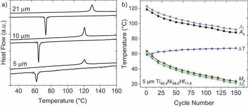
Table 1. Thermal transformation properties of fabricated freestanding TiNiHf films, determined by DSC.
Bi-directional and bistable SMA-based micro- and nano-actuators ideally should last for thousands of actuation cycles with little functional fatigue. The wide thermal hysteresis of ~ΔT = 57 °C indicates poor crystallographic compatibility between the martensite and austenite phase for the fabricated TiNiHf alloy [Citation21]. ) shows functional fatigue of 5 μm thick film after 150 thermal cycles between 0 °C and 140 °C. A decrease in all characteristic transformation temperatures can be seen where the largest change occurs within the first ~20 cycles. The ,
,
, and
temperatures continue to steadily decrease with every cycle without stabilization up to 150 cycles. A decrease in transition temperatures with thermal cycling is expected in TiNi-based alloys due to the introduction of dislocations that compensate for the crystallographic compatibility between the martensite and austenite phases [Citation21]. This fatigue behavior is observed in fabricated freestanding TiNiHf alloys indicated by a slight increase in
with every cycle. Decreasing film thickness and thermal cycling lead to a significant reduction in the latent heat of both the forward and reverse transformation (
,
), which might be beneficial for SMA actuation [Citation50].
3.1.2 Tensile testing
shows a comparison between experimental and simulated stress–strain characteristics of 21 µm thick freestanding TiNiHf films annealed at 635°C – 5 min, structured into a dogbone geometry, at various temperatures in the phase transformation regime. The samples are investigated at three different ambient temperatures of 120 °C, 135 °C, and 155 °C at a constant strain rate of s−1. Simulation results are fit to the experimental results to obtain mechanical parameters such as elastic modulus, maximum transformation strain, critical loading stress, and critical unloading stress values for the stress-induced martensitic transformation.
Figure 2. Experimental and simulated stress–strain curve of the investigated 21 µm thick TiNiHf freestanding films of dogbone geometry size of (see inset). The tests are performed at three different ambient temperatures of 120 °C, 135 °C, and 155 °C with a strain rate of
s−1.
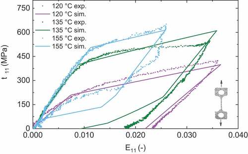
At 120°C, one-way shape memory behavior is obtained upon loading/unloading the samples up to 3.5% strain, indicating the material is in the martensite phase [Citation51]. Reorientation of the martensite variants (detwinning) is suggested to introduce the slip of dislocations. The lack of a stress plateau in Ni-lean TiNiHf alloys is characterized by their low critical stress for slipping [Citation21], strong work hardening behavior, and continuous yielding [Citation25]. The open hysteresis loop with a residual strain of 2.4% indicates the retained stress-induced martensite that is known to form when loading an SMA at a temperature Ms < < Af [Citation51]. At 135°C, the critical stress (
) for phase transformation to martensite is about 430 MPa and a maximum tested strain of 3.4%. The open hysteresis loop with a residual strain of 1.8% indicates the sample is not fully transformed to the austenite phase by 135°C. Upon loading and unloading at 155°C, the critical stress for martensitic transformation shifts to 490 MPa, and the reverse transformation starts at 260 MPa. As a result, a superelastic behavior is obtained with recoverable strain up to 2.6%. The simulated model fit for the 135°C tensile test shows a certain discrepancy with experimental data. Upon unloading, the simulation model overestimates the recoverable strain from 1.8% to 0.95%. However, the superelastic and martensitic forward transformation behavior for all three test conditions is well described by the simulation model. The small discrepancy could be due to microstructural and grain size effects which currently are not captured by the model. This includes the hardening effect that is responsible for the steep slope instead of a stress plateau for TiNiHf films.
3.2 Functional properties of TiNiHf/Si and TiNiHf/SiO2/Si bimorphs
3.2.1 Electrical resistance
The film thickness dependencies of the phase transformation properties of TiNiHf films on Si and SiO2/Si substrates are investigated to understand their impact on bi-directional actuation performance. The transformation hysteresis curves are compared in for all investigated thicknesses from 5 μm down to 0.11 µm on both substrates. Decreasing film thickness leads to a significant increase in resistance with a similar thermal hysteresis width until a critical film thickness is reached for very thin films.
Figure 3. Comparison of resistance–temperature curves of TiNiHf films of different thicknesses on (a) Si and (b) SiO2/Si substrates of 5 mm × 10 mm (see inset for the schematic). Hysteresis width gets significantly larger when films are below critical thickness, which are 0.44 µm for films on Si substrate and 0.22 µm for films on SiO2/Si substrate.
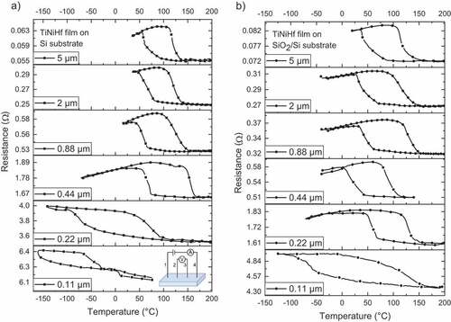
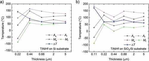
summarizes the corresponding thickness dependence of transformation temperatures and thermal hysteresis width of bimorph films. Data is not shown for the 0.11 µm film on Si substrate as electrical resistance measurements revealed only a partial phase transformation (Ms = −157.4 °C and Af = −23.4 °C) when cooling the sample from room temperature to −160 °C. According to ,
witnesses a dramatic increase when the film thickness is below 0.44 µm for films on Si substrate and below 0.22 µm for films on SiO2/Si substrate, which appear to be critical thicknesses on the corresponding substrates. When the film thickness is below this critical value, the thermal hysteresis shifts to a lower temperature range and the hysteresis width nearly doubles. In contrast, when the film thickness is larger than the critical thickness, the thermal hysteresis width and transformation temperatures show only minor variations.
Figure 4. Transformation temperatures and calculated thermal hysteresis width of TiNiHf films with different thicknesses on (a) Si substrate and (b) SiO2/Si substrate. Data is not shown for 0.1 µm-thin film on Si substrate, as transformation hysteresis is not fully seen in the temperature range −160 °C to 200 °C. All films were annealed at the same condition 635°C – 5 min.
3.2.2 Structural properties
TiNiHf is known to undergo a solid-to-solid phase transformation from a low-symmetry, low-temperature, martensite phase (monoclinic, B19’) to a high-symmetry, high-temperature, austenite phase (cubic, B2). The crystal structures of all TiNiHf films (between 110 nm and 5 μm) on Si and SiO2 substrates were evaluated at room temperature with XRD. shows XRD results at 30 °C for 110 nm, 220 nm, and 440 nm TiNiHf films on both Si and 1.5 μm SiO2/Si substrates. The preferred orientations of martensite and (110) austenite peaks are labeled. Two dominant peaks arise for the martensite phase at 40° for the (002) B19’ phase and 44° for the (020) B19’ phase. The dominant peaks for the austenite phase are located at 42° for the (110) B2 phase and 91° for the (220) B2 phase. The absence (or a weak signal) of these two austenite peaks is the indication that the sample is in martensite phase at room temperature. The large signal at 69° is the peak related to the (100) Si substrates. There were a handful of unidentifiable secondary phase peaks for TiNiHf films on Si substrates that were not observed for TiNiHf films on SiO2/Si substrates. The additional peaks could be due to a (Ti,Hf)2Ni phase that occurs when using Ti-rich TiNi film compositions [Citation4,Citation21]. For a more precise study on the precipitate phases, additional TEM measurements are necessary, which are out of scope for the current study.
Figure 5. XRD results at 30°C for 110 nm, 220 nm, and 440 nm TiNiHf films on (a) Si substrates and (b) on 1.5 μm SiO2/Si substrates. Samples were 20 mm × 20 mm in size.
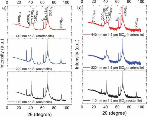
To realize many applications, the main criterion for selecting the film and film composite for martensitic phase transformation has to be above room temperature transformation. shows that 110 nm and 220 nm TiNiHf films on Si substrates are in austenite phase at room temperature. However, for 220 nm films on SiO2/Si buffer layers, XRD shows the SMA is composed of martensite B19’ phase with some residual austenite at room temperature. XRD results indicate the minimum film thicknesses required to obtain a transformation above room temperature are ~220 nm on SiO2/Si substrates and ~440 nm on Si substrates. This confirms both the dramatic film thickness effect below critical film thicknesses and the substrate dependence of this film thickness effect observed in electrical resistance measurements. Fig. S1 (Supporting Information) shows all TiNiHf film thicknesses above the critical thickness value on SiO2/Si substrates transform from the martensite phase at 30°C, to the austenite phase upon heating to 110 °C. 220 nm and 440 nm films on SiO2/ Si substrates were fully transformed to the austenite phase by 110 °C. Films with a thickness greater than 880 nm on SiO2/Si substrates still showed weak (200) and (020) martensite peaks indicating that these samples are still partially martensite at 110 °C.
Temperature-dependent XRD measurements were used to determine the transformation temperatures of TiNiHf films with thicknesses of 110 nm, 220 nm, 440 nm, 880 nm, and 5 μm on Si substrates and a 440 nm thick TiNiHf film on 1.5 μm SiO2/Si substrates. The samples were heated and cooled in 5°C increments between 30°C and 130°C at a heating rate of 10°C/s. By monitoring the change in peak intensity of the B2 austenite peaks at 42° and 91° and using a Rietveld refinement on the (110) B2 cubic austenite phase, it was possible to determine the SMA transition temperatures [Citation52]. The results of the transformation temperatures for all tested films are given in . 110 nm films on SiO2/Si substrates were in the cubic austenite phase, with no transformation taking place in the temperature range between 30 °C and 130 °C. 220 nm films on Si substrates were also found to be in the cubic austenite phase at 30 °C with no transformations taking place between 30 °C and 130 °C (Fig. S2, Supporting Information). 440 nm TiNiHf films on Si substrates were martensite at room temperature and displayed a high temperature phase transformation with = 95.4 °C and
= 108.7 °C. (Fig. S3, Supporting Information). There was not a significant change in transformation temperatures for 440 nm on Si versus 440 nm films on 1.5 μm SiO2/Si substrates. Scanning electron micrsocopy cross-sectional images of different TiNiHf film thicknesses (5 μm, 2 μm, 880 nm, and 440 nm) on Si substrates are shown in Fig. S4 (Supporting Information).
Table 2. Transition temperatures of TiNiHf films on Si substrates and SiO2/si substrates for different thicknesses determined by XRD.
Temperature-dependent XRD data was used to estimate the CTE for austenite phase of the Ti40.4Ni48Hf11.6 alloy by monitoring the change in the cubic lattice parameter while cooling the SMA over a temperature range of 120°C–85°C [Citation53]. The CTE of the austenite phase () was calculated to be
±
from XRD measurements. This value falls between the austenite CTEs reported for binary NiTi (
) [Citation54] and for a Ti29.7Ni50.3Hf20 alloy (
) [Citation13]. For computational simulations, the calculated value from XRD data is used (
=
), and for simplicity, the CTE value for martensite is estimated to be half the value of austenite (
=
).
3.3 Bi-directional actuation based on TiNiHf/SiO2/Si bimorph film composites
Cantilever deflection measurements
Actuation in SMA/Si bimorph cantilevers arises from the combined shape memory effect and CTE difference between bimorph layers [Citation6]. The different stress states in the bimorph cantilever that lead to desirable deflection arise when heating the composite to temperatures above and cooling the composite below
The maximum actuation stroke is determined by the y-deflection obtained between the martensite and austenite phases using CDM.
shows 145 cycles of deflection for 0.88 μm TiNiHf/100 nm SiO2/300 μm Si cantilever composite. The transition temperatures, thermal hysteresis, and maximum stroke upon thermal cycling are given in . A decrease in transformation temperatures and a slight decrease in the actuation stroke are observed with increasing cycles. shows the change in characteristic transformation temperatures as a function of thermal cycles for 0.88 μm TiNiHf/100 nm SiO2/300 μm Si bi-directional actuator. The thermal–mechanical hysteresis stabilized after ~120 cycles, with minor shift in transformation temperatures between cycles 120 and 145. After ~60 cycles, the temperature dropped below minimum test temperature of 30°C; therefore, the material was not fully transformed. The
temperature is marked with a green open symbol in to indicate
< 30 °C. Very small reduction in maximum actuation stroke from 32 μm to 31.5 μm within the first 40 cycles (i.e. an indication of functional fatigue) is observed which then stabilized in the subsequent cycles.
Figure 6. (a) Deflection versus temperature measurements of bi-directional TiNiHf/SiO2/Si actuators with TiNiHf film thicknesses of 0.88 μm on 100 nm buffer layer of SiO2 on 300 μm Si substrates (see inset for the sample picture). (b) Influence of functional fatigue on transition temperatures for the 0.88 μm TiNiHf/SiO2/Si composite. Cantilevers were 3.5 mm × 20 mm in size, with a freestanding cantilever length of 14 mm during measurement.
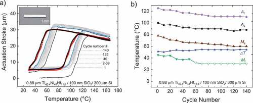
Table 3. Influence of functional fatigue on bi-directional stroke and characteristic transformation temperatures of different TiNiHf thicknesses on 100 nm SiO2/Si substrates.
3.4 Bistable actuation based on PMMA/TiNiHf /Si trimorph film composites
3.4.1 Bistable actuation principle
The unique properties of TiNiHf/Si bimorph films of large hysteresis and an temperature larger than 105 °C open the opportunity for the design of bistable actuation using a polymer layer on TiNiHf/Si composite. As depicted in the schematic in , SMA/Si bimorph structures can become bistable if combined with a polymer with matching glass transition temperature (
). That means the glass transition temperature of the polymer is required to fall within the thermal hysteresis of the SMA (
<
<
) [Citation55]. Assume the composite is in stable state I, as shown in . In order to switch to stable state II, the composite is heated above austenite finish temperature (
<
), allowing the polymer to soften and adapt to the deflected shape of the composite. Upon cooling below
, the polymer will become hard and, thereby, fixes the deflected shape that corresponds to stable state II. In order to recover stable state I, the composite is heated to intermediate temperature
(
<
), and the polymer becomes soft again and adapts to the initial shape in martensite phase, which will be fixed upon cooling to room temperature. The fixation effect will be effective if the thickness of the polymer is large enough.
Figure 7. (a) Schematic of interlaced polymer and SMA hysteresis, enabling bistability. (b) Superimposed stable states (I) and (II) for comparison. The cross section of the trimorph layers (PMMA/TiNiHf/Si) is sketched.
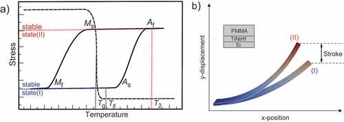
Here, we use PMMA as the polymer in a PMMA/TiNiHf/Si trimorph composite. PMMA is a standard resist material in various lithography methods such as X-ray lithography, deep UV-lithography, and E-beam lithography techniques Citation49,Citation56–58]. The glass transition temperature of PMMA is 105 , which fulfills the criteria for bistability.
3.4.2 Polymer and Si model
Since the PMMA in mind does not exhibit shape memory effects, the polymer is modeled as a passive material. This is done by using a thermally coupled viscoelastic Maxwell model for finite strains [Citation59], where the viscosity is at low temperatures below
and
at high temperatures. Thus, the polymer is soft above
, while still being stiff at colder temperatures. For simplicity, the CTE
[Citation60,Citation61,Citation62], Young’s modulus (500 MPa), and Poisson’s ratio (0.4) of the PMMA polymer are held constant in simulations. The Si layer is modeled using a thermally coupled Neo-Hookean elastic model with Young’s modulus of 130 GPa and Poisson’s ratio being equal to 0.278 [Citation61]. The CTE of Si is
[Citation11]. The SiO2 buffer layer is neglected in simulations as it is not expected to influence the mechanical properties of the composite.
3.4.3 Actuator geometry and boundary conditions
The modeled actuator has a length of 1 mm and a width of 100 µm. The Si and SMA films have a thickness of 2 µm and 1 µm, respectively. The geometry is discretized by 20 elements over its length and 6 over its width, whereas each layer of material is discretized by 4 elements over the thickness. At the left side, it is clamped, i.e. the displacements on the left side are constrained to be zero. Additionally, at the top and bottom of the thin film, a Robin boundary condition with a convective heat transfer coefficient of [Citation63] is used to model heat convection with the surrounding air, which has a temperature of
. Furthermore, Joule heating is realized through a heat source term in the TiNiHf. The actuator model is shown in .
3.4.4 Optimization of polymer thickness
The actuator’s maximum bistable stroke is strongly dependent on the polymer layer thickness. If the layer is too thin, it is not able to hold the austenite-related shape at room temperature. If the polymer layer is too thick, it hampers the stroke and limits the actuation speed as well as power consumption. Additionally, larger body forces and less freedom for the thermal hysteresis of the SMA limit the design space of the actuator. Therefore, we optimize the polymer geometry by simulating several thicknesses. For clarity, only two polymer thicknesses of this sweep are shown in , where the achieved vertical displacement and the temperature in the middle of the SMA at the end of the beam are plotted over time. In the beginning, we start with the actuator at room temperature, which is held by the polymer in stable state (I). Subsequently, the actuator undergoes a low heat cycle (1–2) in , in which the polymer softens and releases the stress, which results in the flattened, stable state (I). After that, the actuator is heated above (3–4). Next, it is cooled down to room temperature again (5), at which it returns to stable state (II) again.
Figure 8. (a) Demonstration of bistable actuation of PMMA/TiNiHf/Si through simulation assuming a of 105°C. (b) FEM simulation of maximum bistable stroke versus polymer thickness for a cantilever consisting of a PMMA/TiNiHf/Si trimorph composite with TiNiHf and Si layer thicknesses of 1 µm and 2 µm, respectively. The cantilever length
and width
are 1 mm and 100 µm, respectively.
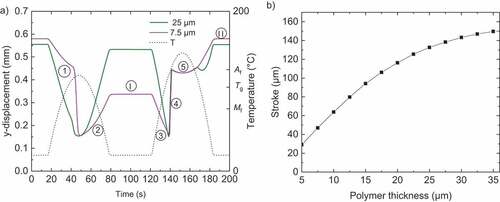
When reaching , depending on the polymer thickness, it can hold the shape (e.g. for 25 µm) or release most of the actuation (e.g. for 7.5 µm, shown in ). Additionally, since the area moment of inertia depends in a cubic manner on the polymer layer thickness, any thinner layers result in less achievable stroke. The influence of the polymer layer onto the achievable bistable stroke is depicted in , where the difference between the vertical displacement of stable states (I) and (II) is compared. Furthermore, favorable thickness combinations for smaller actuator geometries and stack sizes are listed in . The maximum relative bistable strokes (∆y/L) show a scaling-dependent decrease when reducing the lateral dimensions
from
down to
. Yet, even for the smallest bistable device, a considerable bistable stroke of 4% is expected, which is of special interest for actuator applications at ultra-small scales. Because the model at hand does not inherit any size effects, further model refinement might be required considering additional effects such as grain size, oxidation, compositional or other influences affecting the actuation behavior. Furthermore, the
of PMMA is dependent on parameters such as film thickness and polymer molecular weight. Additionally, both the
and CTE are dependent on the interfacial energy between the polymer film and substrate and the exposure dose used during structuring [Citation56–58]. These processing and scaling effects are not captured by the model and must be taken into account when designing bistable actuators with PMMA/TiNiHf/Si trimorph composites.
Table 4. Simulated stroke of downsized trimorph actuator geometries.
4. Discussion
The shape memory properties of TiNiHf/SiO2/Si bimorph composites were characterized experimentally for use as micro and nano bi-directional actuators. Controlling functional fatigue characteristics upon thermal cycling in Ni-lean TiNiHf is pivotal in the development of bi-directional actuators. DSC and CDM results showed that the transition temperatures of fabricated TiNiHf freestanding films and TiNiHf/SiO2/Si bimorph composites decrease with thermal cycling. The change in transition temperatures with cycling is reduced for TiNiHf films bound to an SiO2/Si substrate compared to the functional fatigue DSC results reported for freestanding films from . An average reduction in transition temperatures of 12 °C–18 °C is obtained for 0.88 μm TiNiHf/SiO2/Si composites after 140 cycles compared to an average reduction in transition temperatures of 29 °C–38°C for 5 μm freestanding TiNiHf films after 140 cycles. Additionally, XRD and CDM show thermal hysteresis width is also reduced for TiNiHf films constrained by SiO2 and Si substrates compared to freestanding films of similar thicknesses. This might imply an improvement in the compatibility of the austenite and martensite phases for films constrained by a substrate. The Si and SiO2/Si substrates cause an inhomogeneous stress profile at the film–substrate interface, which may affect phase transformation temperatures as it poses an additional energy barrier for the formation of martensite upon cooling [Citation8].
Based on the analysis of our experimental results, we can infer a pronounced substrate influence as well as a dramatic film thickness effect below a substrate-dependent critical film thickness on the phase transformation properties of TiNiHf films. Freestanding TiNiHf films show a thickness-dependent decrease of all characteristic transformation temperatures of ~10 °C when reducing thickness from 21 µm to 5 µm. Similarly, decreasing the SMA’s thickness was found to decrease the martensitic transformation temperatures for SMA wires (e.g. NiMnGa [Citation63]), freestanding films (e.g. TiNiCu [Citation32], NiTi [Citation30,Citation31]), and sputtered bimorph systems (e.g. NiMnGa/Si [Citation8], NiTi/Si [Citation31], NiTi/Pt [Citation64,Citation65], Ti2NiCu/Pt [Citation32]). This thickness effect can also be seen for TiNiHf with decreasing film thickness from 5 µm down to 110 nm constrained on Si and SiO2/Si substrates. There is a critical thickness of TiNiHf films on both Si and SiO2/Si substrates, below which the thermal hysteresis width increases significantly. Temperature-dependent electrical resistance measurements and XRD measurements are in agreement that these values are between 110 nm and 220 nm for films on SiO2/Si substrates and between 220 nm and 440 nm for films on Si substrates.
This shows evidence that the interface between the substrate and TiNiHf film plays an important role in the phase transformation and is more pronounced below a critical thickness. The existence of the observed critical thickness values could also be ascribed to a change in the composition of the TiNiHf film due to diffusion at the surface and interface of the substrate during the annealing process. One explanation of the change is a TiOx oxidation layer on the surface of the SMA film [Citation31,Citation65], which is claimed to affect films with a thickness below 1 µm [Citation32,Citation65]. The oxidation layer will create a Ti-lean zone beneath, which is much thicker than the oxidation layer, changing the composition of the film. The effect of the SiO2 buffer layer on the change of the critical thickness to lower values might be attributed to the effect of diffusion as well. Jarrige et al. [Citation65] propose that for binary NiTi systems, there is an additional TiOx oxidation layer between the film and SiO2/Si substrate, and this layer can hinder the diffusion of Ni and Si atoms between the film and the substrate, as was observed for films annealed on Si substrates. Furthermore, the stress at the TiNiHf/Si interface might be reduced due to stress release by the intermediate SiOx layer, which affects phase transformation at small SMA layer thicknesses. These considerations help to understand that the critical thickness of TiNiHf films on SiO2/Si substrate could be smaller than that on Si substrate. However, further investigations on the layer sequence (addition of buffer layers and diffusion barriers like Si3N4 or Ta) of bimorph sample sections are needed for better understanding.
The transition temperatures deduced from different experimental methods of DSC, XRD, electrical resistance, and bi-directional deflection reveal systematic deviations. The different length scales and different loading conditions may cause major differences. While XRD probes undergo phase transformation at the local scale, electrical resistance reveals average values of the whole test specimen. Bi-directional bending reflects the non-uniform stress profiles during beam bending, which is absent in DSC. Another difference is ascribed to the different time scales of temperature cycling in the phase transformation regime. In particular, electrical resistance measurements have been performed by providing sufficient waiting time between data points to enable quasi-stationary equilibrium conditions, while DSC experiments have been conducted using a fixed heating and cooling rate. However, these details are not the focus of this investigation. Conclusions are drawn based on the dependencies observed by each experimental method independently, while direct comparisons are avoided.
The experimental results shown in this work envisage a possible route for developing bistable actuators using additional polymer layer to TiNiHf/Si bimorphs. The biggest challenge in experimentally realizing such bistable devices is tailoring transformation temperatures of TiNiHf to match the of PMMA. Simulations incorporated the experimental results on TiNiHf phase transformation properties accounting for substrate influence and film thickness effects that arise when downscaling to nanofilms. Simulation results indicated that trimorph PMMA/TiNiHf/Si film composites exhibit large bistable actuation with scaling-dependent bistable stroke per length
. The simulation results should be considered as an outlook and guideline for future experimental work.
5. Conclusions
For the investigated chemical composition of Ti40.4Ni48Hf11.6 and optimized annealing conditions of 635°C – 5 min, it is found that decreasing the layer thickness of TiNiHf in bimorph composites decreases the phase transformation temperatures. A large reduction of /
by more than 100 °C is observed when TiNiHf film thickness drops below a critical thickness. The onset of the film thickness effect depends on the substrate. For Si substrates, critical thickness occurs between 440 nm and 220 nm, while for 1.5 μm SiO2 buffer/Si substrate it occurs between 220 nm and 110 nm. Functional fatigue was improved for TiNiHf films in bi-directional TiNiHf/SiO2/Si composites as compared to freestanding TiNiHf films. The fabricated bi-directional actuator demonstrated a stable actuation stroke after 40 thermal cycles and thermal stability after 125 cycles. Freestanding films, on the other hand, achieved were not stabilized in the first 150 thermal cycles. Tailoring the substrate and film properties of TiNiHf films above room temperature leads to the possibility to use these films for advanced nano- or micro-actuation. To further investigate the utility of these films for the actuation, simulations were carried out by adding an additional PMMA layer to show that with this material system, bistable actuation can be achieved at nanoscales. Once functional fatigue is controlled in sputtered TiNiHf/SiO2/Si film composites, these results show they are promising materials for nanoscale actuation to enable novel applications in nanomechanics and photonics.
Acknowledgments
S. Curtis gratefully acknowledges support from the National Science Foundation Graduate Research Fellowship under Grant No. DGE 1840340. We acknowledge Kaiju Lu at the Institute for Applied Materials (KIT-IAM) for access to temperature-dependent tensile test experiments. The authors would like to thank Afrin Shara for her assistance with fabrication and thermal characterization.
Disclosure statement
No potential conflict of interest was reported by the author(s).
Additional information
Funding
References
- Errando-Herranz C, Takabayashi AY, Edinger P, et al. MEMS for photonic integrated circuits. IEEE J Sel Top Quantum Electron. 2019;26(2):1.
- Ollier E. Optical MEMS devices based on moving waveguides. IEEE J Sel Top Quantum Electron. 2002;8(1):155.
- Lee H-T, Kim M-S, Lee G-Y, et al. Shape memory alloy (sma)-based microscale actuators with 60\% deformation rate and 1.6 kHz actuation speed. Small. 2018;14(23):1801023.
- König D, Zarnetta R, Savan A, et al. Phase transformation, structural and functional fatigue properties of Ti–Ni–Hf shape memory thin films. Acta Materialia. 2011;59(8):3267.
- Karaca HE, Saghaian SM, Ded G, et al. Effects of nanoprecipitation on the shape memory and material properties of an Ni-rich NiTiHf high temperature shape memory alloy. Acta Materialia. 2013;61(19):7422.
- Karakoc O, Hayrettin C, Bass M, et al. Effects of upper cycle temperature on the actuation fatigue response of NiTiHf high temperature shape memory alloys. Acta Materialia. 2017;138(185). DOI:10.1016/j.actamat.2017.07.035
- Choudhary N, Kaur D. Shape memory alloy thin films and heterostructures for MEMS applications: a review. Sens Actuators A. 2016;242(162). DOI:10.1016/j.sna.2016.02.026
- Lambrecht F, Lay C, Aseguinolaza IR, et al. NiMnGa/Si shape memory bimorph nanoactuation. Shape Memory and Superelasticity. 2016;2(4):347
- Winzek B, Schmitz S, Rumpf H, et al. Recent developments in shape memory thin film technology. Mater Sci Eng A. 2004;378(1–2):40.
- Rastjoo S, Fechner R, Bumke L, et al. Development and co-integration of a SMA/Si bimorph nanoactuator for Si photonic circuits. Microelectronic Engineering. 2020;(225). p. 111257.
- Watanabe H, Yamada N, Okaji M. Linear thermal expansion coefficient of silicon from 293 to 1000 K. Int J Thermophys. 2004;25(1):221.
- Shuitcev A, Vasin RN, Fan XM, et al. Volume effect upon martensitic transformation in Ti29. 7Ni50. 3Hf20 high temperature shape memory alloy. Scr Mater. 2020;178:67.
- Shuitcev A, Vasin RN, Balagurov АM, et al. Thermal expansion of martensite in Ti29. 7Ni50. 3Hf20 shape memory alloy. Intermetallics. 2020;125:106889.
- Winzek B, Sterzl T, Quandt E Bistable thin film composites with TiHfNi-shape memory alloys. Transducers ’01 Eurosensors XV Berlin, Heidelberg, Germany. 2001. p. 706–709.Springer.
- Taya M, Liang Y, Namli OC, et al. Design of two-way reversible bending actuator based on a shape memory alloy/shape memory polymer composite. Smart Mater Struct. 2013;22(10):105003.
- Sterzl T, Winzek B, Rumpf H, et al. Bistable shape memory composites for switches, grippers and adjustable capacitors in Proceedings of the 8th International Conference on New Actuators, Actuator Bremen, Germany (2002), pp. 91–94.
- Vitushinsky R, Schmitz S, Ludwig A. Bistable thin-film shape memory actuators for applications in tactile displays. J Microelectromech Syst. 2008;18(1):186.
- Winzek B, Schmitz S, Vitushinsky R. Shape memory actuators in mobile robots for planetary surface exploration in Tools and Technologies for Future Planetary Exploration Noordwijk, The Netherlands. 2004: 115–120
- Karaca HE, Acar E, Tobe H, et al. NiTiHf-based shape memory alloys. Mater Sci Technol. 2014;30(13):1530.
- Karakoc O, Hayrettin C, Evirgen A, et al. Role of microstructure on the actuation fatigue performance of Ni-Rich NiTiHf high temperature shape memory alloys. Acta Materialia. 2019;175(107). DOI:10.1016/j.actamat.2019.05.051
- Tong Y, Shuitcev A, Zheng: Y. Recent development of TiNi-based shape memory alloys with high cycle stability and high transformation temperature. Adv Eng Mater. 2020;22(4):1900496.
- Evirgen A, Karaman I, Santamarta R, et al. Relationship between crystallographic compatibility and thermal hysteresis in Ni-rich NiTiHf and NiTiZr high temperature shape memory alloys. Acta Materialia. 2016;121(374). DOI:10.1016/j.actamat.2016.08.065
- Bechtold C, Chluba C, Zamponi C, et al. Fabrication and characterization of freestanding NiTi based thin film materials for shape memory micro-actuator applications. Shape Memory and Superelasticity. 2019;5(4):327
- Motemani Y, McCluskey PJ, Zhao C, et al. Analysis of Ti–Ni–Hf shape memory alloys by combinatorial nanocalorimetry. Acta materialia. 2011;59(20):7602.
- Meng XL, Zheng YF, Cai W, et al. Two-way shape memory effect of a TiNiHf high temperature shape memory alloy. J Alloys Compd. 2004;372(1–2):180.
- Meng XL, Cai W, Chen F, et al. Effect of aging on martensitic transformation and microstructure in Ni-rich TiNiHf shape memory alloy. Scr Mater. 2006;54(9):1599.
- Meng XL, Cai W, Fu YD, et al. Shape-memory behaviors in an aged Ni-rich TiNiHf high temperature shape-memory alloy. Intermetallics. 2008;16(5):698.
- Mandepudi SK, Ackler HD. Processing and characterization of composite shape memory alloy (SMA) thin film structures for microactuators. Behavior and Mechanics of Multifunctional Materials and Composites. 2010. 7644.
- Grummon DS. Thin-film shape-memory materials for high-temperature applications. JOM. 2003;55(12):24.
- Waitz T, Kazykhanov V, Karnthaler HP. Martensitic phase transformations in nanocrystalline NiTi studied by TEM. Acta Materialia. 2004;52(1):137.
- Ishida A, Sato: M. Thickness effect on shape memory behavior of Ti-50.0 at % Ni thin film. . Acta Materialia. 2003;51(18):5571
- König D, Ehmann M, Thienhaus S, et al. Micro-to nanostructured devices for the characterization of scaling effects in shape-memory thin films. J Microelectromech Syst. 2010;19(5):1264.
- Meng XL, Cai W, Fu YD, et al. Martensite structure in Ti–Ni–Hf–Cu quaternary alloy ribbons containing (Ti, Hf) 2Ni precipitates. Acta Materialia. 2010;58(10):3751.
- Meng XL, Cai W, Wang LM, et al. Microstructure of stress-induced martensite in a Ti–Ni–Hf high temperature shape memory alloy. Scr Mater. 2001;45(10):1177.
- Meng XL, Cai W, Zheng YF, et al. Stress-induced martensitic transformation behavior of a Ti–Ni–Hf high temperature shape memory alloy. Mater Lett. 2002;55(1–2):111.
- Yi X, Meng X, Cai W, et al. Multi-stage martensitic transformation behaviors and microstructural characteristics of Ti-Ni-Hf high temperature shape memory alloy powders. J Alloys Compd. 2019;781(644). DOI:10.1016/j.jallcom.2018.12.064
- Winzek B, Sterzl T, Rumpf H, et al. Composites of different shape memory alloys and polymers for complex actuator motions in. Journal de Physique IV (Proceedings). 2003:1163–1168. DOI: 10.1051/jp4:20031089.
- Sanjabi S, Cao YZ, Barber ZH. Multi-target sputter deposition of Ni50Ti50- xHfx shape memory thin films for high temperature microactuator application. Sens Actuators A. 2005;121(2):543.
- Lima De Miranda R, Zamponi C, Quandt E. Micropatterned freestanding superelastic TiNi films. Adv Eng Mater. 2013;15(1–2):66.
- Sedlák P, Frost M, Benešová B, et al. Thermomechanical model for NiTi-based shape memory alloys including R-phase and material anisotropy under multi-axial loadings. Int J Plast. 2012;39(132). DOI:10.1016/j.ijplas.2012.06.008
- Sielenkämper M, Wulfinghoff S. A thermomechanical finite strain shape memory alloy model and its application to bistable actuators. In: Acta Mechanica. 2022.
- Hurtado DE, Stainier L, Ortiz M. The special-linear update: An application of differential manifold theory to the update of isochoric plasticity flow rules. Int J Numer Method Biomed Eng. 2014;97(4):298.
- Sielenkämper M, Dittmann J, Wulfinghoff S. Numerical strategies for variational updates in large strain inelasticity with incompressibility constraint. Int J Numer Method Biomed Eng. 2022;123(1):245–267.
- Halphen B, Nguyen QS Sur les matériaux standard généralisés(1975).
- Yang Q, Stainier L, Ortiz M. A variational formulation of the coupled thermo-mechanical boundary-value problem for general dissipative solids. J Mech Phys Solids. 2006;54(2):401.
- Lexcellent C, Boubakar ML, Bouvet C, et al. About modelling the shape memory alloy behaviour based on the phase transformation surface identification under proportional loading and anisothermal conditions. Int J Solids Struct. 2006;43(3):613.
- Panico M, Brinson LC. A three-dimensional phenomenological model for martensite reorientation in shape memory alloys. J Mech Phys Solids. 2007;55(11):2491.
- Taylor RL FEAP - Finite Element Analysis Program 2017.
- Arivanandhan G, Li Z, Curtis S Temperature Homogenization of Co-Integrated Shape Memory—Silicon Bimorph Actuators, et al. in Multidisciplinary Digital Publishing Institute Proceedings. 2020;(64), p. 8.
- Tabesh M, Lester B, Hartl D, et al. Influence of the latent heat of transformation and thermomechanical coupling on the performance of shape memory alloy actuators Proceedings of the ASME 2012 Conference on Smart Materials, Adaptive Structures and Intelligent Systems. 2012(2);237–248.
- Turner TL Thermomechanical Response of Shape Memory Alloy Hybrid Composites (DIANE Publishing, 2001).
- Uchil J, Fernandes FMB, Mahesh KK. X-ray diffraction study of the phase transformations in NiTi shape memory alloy. Mater Charact. 2007;58(3):243.
- Zamkovskaya A, Maksimova E, Nauhatsky I, et al. X-ray diffraction investigations of the thermal expansion of iron borate FeBO3 crystals in Journal of Physics: Conference Series Saint-Petersburg, Russia 2017. p. 12030.
- Qiu S, Krishnan VB, Padula SA, et al. Measurement of the lattice plane strain and phase fraction evolution during heating and cooling in shape memory NiTi. Appl Phys Lett. 2009;95(14):141906.
- Winzek B, Sterzl T, Rumpf H Thin film shape memory composites Nato conference on martensitic phase transformation Metz, France . Metz, France; 2002.
- Fryer DS, Peters RD, Kim EJ, et al. Dependence of the glass transition temperature of polymer films on interfacial energy and thickness. Macromolecules. 2001;34(16):5627.
- Lan T, Torkelson JM. Methacrylate-based polymer films useful in lithographic applications exhibit different glass transition temperature-confinement effects at high and low molecular weight. Polymer. 2014;55(5):1249.
- Kahle O, Wielsch U, Metzner H, et al. Glass transition temperature and thermal expansion behaviour of polymer films investigated by variable temperature spectroscopic ellipsometry. Thin Solid Films. 1998;313-314(803–807).
- Reese S, Govindjee S. Theoretical and numerical aspects in the thermo-viscoelastic material behaviour of rubber-like polymers. Mech Time-Dependent Mater. 1997;1(4):357.
- S. H. Goods. Thermal expansion and hydration behavior of PMMA moulding materials for LIGA applications (2003).
- Hopcroft MA, Nix WD, Kenny TW. What is the young’s modulus of silicon? J Microelectromech Syst. 2010;19(2):229.
- Zhang Y, Li M, Wang YD, et al. Superelasticity and serration behavior in small-sized NiMnGa alloys. Adv Eng Mater. 2014;16(8):955.
- Knick CR, Smith GL, Morris C. J, et al. Rapid and low power laser actuation of sputter-deposited NiTi shape memory alloy (SMA) MEMS thermal bimorph actuators. Sens Actuators A. 2019;291(48–57).
- Lega P, Nedospasov I, Orlov A, et al. On the Fundamental Limits of the Size of the Shape Memory Nanoactuators Posed by Martensitic Transition in Ti2NiCu Shape Memory Alloy on Nano-Scale. 2019 IEEE international conference on ManipulationManufacturing and Measurement on the Nanoscale (3M-NANO) Zhenjiang, China; 2019. p. 90–93.
- Jarrige I, Holliger P, Jonnard P. Diffusion processes in NiTi/Si, NiTi/SiO2 and NiTi/Si3N4 systems under annealing. Thin Solid Films. 2004;458(1–2):314.