
 ?Mathematical formulae have been encoded as MathML and are displayed in this HTML version using MathJax in order to improve their display. Uncheck the box to turn MathJax off. This feature requires Javascript. Click on a formula to zoom.
Abstract
This paper studies the trajectory tracking problem of quadrotor unmanned aerial vehicle (QUAV) with model nonlinearities and external disturbances via event-triggered control technique. Dividing the QUAV system into position subsystem and attitude subsystem, an adaptive fuzzy control algorithm is designed in position subsystem to provide desired pitch and roll angles for the attitude subsystem. Then, by constructing an event-triggered mechanism, an event-triggered adaptive fuzzy control algorithm is presented in the attitude subsystem, where the control law and the fuzzy parameter adaptive law are updated in an aperiodic form. Based on Lyapunov stability theory, it is proved that all signals in the closed-loop system are uniformly ultimately bounded via the impulsive dynamical system tool, and the tracking errors converge to a small neighbourhood of the origin. Besides, it is proved that there is a positive lower bound between the intersample time to avoid Zeno behaviour. Finally, simulation results illustrate that the proposed control scheme can guarantee the trajectory tracking performance of the QUAV system, while it can reduce the update frequency of the controller and improve the resource utilization.
1. Introduction
Recently, QUAV has been widely applied in various fields, such as transportation, video surveillance, business performance and post-disaster rescue. In these areas, it is often required to achieve accurate tracking performance (Adlakha & Zheng, Citation2020). However, QUAV is an under-actuated and multi-input multi-output system with nonlinearities and strong coupling characteristics. The uncertain terms together with external disturbances have great affect on the tracking performance. Thus, it is more challenging to design the tracking control algorithms of QUAV (Özbek et al., Citation2015).
Numerous research results on the trajectory tracking of QUAV are available (Antonio-Toledo et al., Citation2018; Chen et al., Citation2016; Choi & Ahn, Citation2015; Emam & Fakharian, Citation2016; Liu et al., Citation2016). For example, a set point tracking control is presented for QUAV with known dynamics via the feedback linearization method in Choi and Ahn (Citation2015). A sliding mode controller is designed for QUAV with uncertain parameters and external disturbances in Chen et al. (Citation2016) and Antonio-Toledo et al. (Citation2018). Robust compensation technique is introduced to restrain the model uncertainties and external disturbance in Liu et al. (Citation2016). Hybrid robust H and controllers are constructed to suppress the influence of measurement noise and external disturbances based on LMI method in Emam and Fakharian (Citation2016). In addition, adaptive trajectory control algorithms are proposed to identify the upper bounds of unknown parameters and external disturbances in Zuo (Citation2013), Antonelli et al. (Citation2017) and Wang et al. (Citation2017). State estimation technique is adopted to QUAV systems (Luo et al., Citation2021, Citation2020). In Zhang et al. (Citation2020), Ai and Yu (Citation2020) and Zhang, J. Q. et al. (Citation2019), trajectory tracking control methods based on active disturbance rejection control are proposed by introducing disturbance observers and extended state observers.
The intelligent adaptive control based on fuzzy logic systems (FLSs) or neural networks (NNs) becomes an effective tool to solve the control problem of uncertain nonlinear systems (Li et al., Citation2010; Tong et al., Citation2014; Wang & Huang, Citation2005). An adaptive NN position tracking controller based on backstepping recursive technique is designed in Ariffanan and Basri (Citation2018), where the time-varying external disturbances are approximated by NNs and the controller parameters are optimized by gravitational search algorithm. Using FLSs to approximate unknown external disturbances, an adaptive fuzzy position tracking control algorithm is presented in Xu et al. (Citation2019). In the work (Zhou et al., Citation2018), an adaptive NN finite-time tracking control algorithm is proposed, which can effectively restrain the influence of input saturation on the control performance. By introducing a fuzzy state observer to estimate the system states, an adaptive fuzzy output feedback trajectory tracking control is designed in Mallavalli and Fekih (Citation2020) and Wang and Wang (Citation2018). Despite some effective control algorithms are developed for the trajectory tracking of QUAV, most of the aforementioned control algorithms are continuously updating, even though it has achieved satisfactory control performance.
In practical application, the control algorithm of QUAV is implemented by airborne embedded micro processing unit. Therefore, the continuous control algorithms or the fixed period updating control algorithms will increase the processor computation, which will further lead to the redundant communication and energy consumption. Note that event-triggered control (ETC) has been receiving increased attention and fruitful theoretical researches have been developed (Li, Alsaadi et al., Citation2020; Li, Wang et al., Citation2020; Li & &Yang, Citation2018; Postoyan et al., Citation2015; Xing et al., Citation2017). The ETC algorithm is updated in an aperiodic form according to the performance index while maintaining satisfied control performance. On the above basis, the trajectory tracking control problem of QUAV based on ETC is studied in Zhang, J. Q. et al. (Citation2019), Wang et al. (Citation2019) and Wang et al. (Citation2020). In Zhang, M. et al. (Citation2019), using weight multi-model method to model the nonlinear QUAV system, a position tracking controller is designed based on LMI technique, and an event-triggered mechanism is designed to determine the update instants of control signal. Robust sliding mode controllers are proposed both in the position and attitude loop to eliminate the external disturbances in Wang et al. (Citation2019), where the attitude tracking controller is updated in an aperiodic form based on the event-triggered mechanism. In Wang et al. (Citation2020), a robust adaptive attitude tracking controller based on ETC is proposed, where the upper bound of the external disturbance is estimated via the adaptive control technique. It is worth pointing out that the mentioned ETC based trajectory tracking control algorithms limit to QUAV with known dynamics. To our best knowledge, it is still an open problem for the intelligent adaptive ETC based on the trajectory tracking of QUAV with unknown dynamics and external disturbances, which motivates our research.
Based on the above research results, this paper proposes an adaptive fuzzy trajectory tracking control algorithm based on ETC technique for QUAV with model nonlinearities and external disturbances. In the control design, an adaptive fuzzy position tracking control is designed first. Then, an adaptive event-triggered mechanism is constructed in the attitude subsystem, and an event-triggered adaptive fuzzy attitude tracking control is developed. The contributions are summarized as follows.
In this article, an event-triggered mechanism is introduced in the attitude control loop to determine the instants of information transmission. Based on the designed event-triggered mechanism, the adaptive fuzzy attitude tracking controller is updated only when the prescribed error exceeds a given threshold, which is different from the continuously updating control algorithms given in Zuo (Citation2013), Antonelli et al. (Citation2017), Wang et al. (Citation2017), Zhang et al. (Citation2020), Ai and Yu (Citation2020), Zhang, M. et al. (Citation2019), Ariffanan and Basri (Citation2018), Xu et al. (Citation2019), Zhou et al. (Citation2018), Mallavalli and Fekih (Citation2020) and Wang and Wang (Citation2018). Under the proposed control protocol, the QUAV system can achieve satisfactory control performance while the calculation cost and communication pressure are greatly reduced.
By utilizing FLSs to identify the lumped nonlinearities online, an event-triggered adaptive fuzzy tracking control is developed for QUAV with model nonlinearities and external disturbances. Note that the existing ETC algorithms in Zhang, M. et al. (Citation2019), Wang et al. (Citation2019) and Wang et al. (Citation2020) require the precise model information of QUAV. Besides, an adaptive event-triggered mechanism is constructed based on measurement error and the fuzzy adaptive parameters in this article, and both the controller and the adaptive parameter in the attitude control loop are updated in an aperiodic form under the designed event-triggered mechanism, while the adaptive parameter is continuously updated under the event-triggered mechanism in Wanget al. (Citation2020).
2. Problem description
2.1. The model of the QUAV
In Figure , take the four machine arms intersection as the coordinate centre, then the body coordinate of the ‘X’ type QUAV system
can be built, where
axis is points to the forward direction of the nose,
axis is points to the opposite extension of the earth's centre and the positive direction of the
axis is determined by the right-hand rule.
Figure 1. The coordinate of the QUAV system.
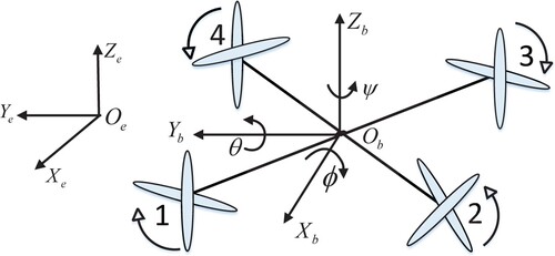
Take the QUAV take-off position as the origin of the earth coordinate system
, where the direction of the
axis points to the East, the direction of the
axis points to the reverse extension line of the
axis which pointing to the earth centre, and the direction of the
axis is determined by the right-hand rule.
The position coordinate and the attitude coordinate of QUAV are established under the earth coordinate and the body coordinate, respectively. The two coordinates can be transformed through the rotation matrix. The position subsystem and the attitude subsystem of QUAV will be established respectively for analysis in this section.
The mathematical model of the QUAV position subsystem can be expressed as Wang et al. (Citation2017)
(1)
(1) where
(2)
(2)
(3)
(3)
(4)
(4)
and
denote the position vector and velocity vector of the QUAV.
is the input of the position subsystem,
represents the sum of the lift generated by the four rotors.
is the Euler angle vector, where ψ, θ, ϕ are the yaw, pitch and roll angle, which rotate around the Z, Y and X axes respectively. The nonlinear external disturbance is express as
. Moreover,
, m, g are the air damping coefficient, the mass of the QUAV and the acceleration of the gravity.
The mathematical model of the QUAV attitude subsystem can be expressed as
(5)
(5) where
(6)
(6)
(7)
(7)
and
denote the angular velocity vector and the input torque vector of the attitude subsystem. The nonlinear external disturbance is express as
. Moreover,
diag
and l is the inertia matrix of the QUAV and the distance from one of the four motors to the centre of the QUAV.
2.2. Fuzzy logic system
An FLS consists of the knowledge base, the fuzzifier, the fuzzy inference engine and the defuzzifier. The fuzzy inference engine comprises a collection of the following if-then rules:
where
and
are the FLS input and output, respectively.
and
represent fuzzy sets.
, where N represents the number of the rules. Through singleton function, centre average defuzzification and product inference, the FLS can be expressed as
(8)
(8) where
and
are the fuzzy functions of the
and
,
. Define the fuzzy basis function as
(9)
(9) By choosing
and
, the FLS can be expressed as
(10)
(10)
Lemma 2.1
Let be a continuous function defined on a compact set
. Then for any constant
, there exists an FLS such as
(11)
(11)
According to Lemma 2.1, the unknown nonlinear part and
of the position subsystem (Equation1
(1)
(1) ) and the attitude subsystem (Equation5
(5)
(5) ) can be approximated by an FLS as follows.
(12)
(12) where
and
represent the optimal parameter vector and the fuzzy basis function vector. Moreover, the minimum fuzzy approximation errors
satisfies the unequal formula
, where
are the arbitrary positive constants in the compact set
, and
and
are the compact sets of the
and
.
Assumption 2.1
The given desired trajectory and the desired yaw angle
are known and their first and second derivatives are bounded.
Assumption 2.2
The fuzzy basis function vector satisfies the global Lipschitz continuity condition, such that
, where
is the known constants.
Remark 2.1
Assumption 2.1 is a reasonable and mild assumption, since in the trajectory tracking of QUAV, the desired trajectory and yaw angle always change in a certain region. Assumption 2.2 indicates that the fuzzy basis function vector satisfies the local Lipschitz continuity condition. It is a common assumption in fuzzy or NN-based control design. Similar assumption can also be found in Tong et al. (Citation2014).
3. Adaptive fuzzy position tracking control design
In this section, an adaptive fuzzy trajectory tracking control algorithm will be performed in the position loop based on backstepping control technique.
Step 3.1
Define the position tracking error vector for the subsystem (Equation1(1)
(1) ) as
(13)
(13) Differentiating (Equation13
(13)
(13) ) along with (Equation1
(1)
(1) ), we have
(14)
(14) The virtual control law is designed as
(15)
(15) where
is the gain matrix.
Let pass through a first-order filter to obtain the filtered output
:
(16)
(16) where
is filter time constant. Then, the filter error is constructed as
(17)
(17) From (Equation16
(16)
(16) ) and (Equation17
(17)
(17) ), we obtain
(18)
(18) Considering (Equation15
(15)
(15) ) and (Equation17
(17)
(17) ), (Equation14
(14)
(14) ) can be rewritten as
(19)
(19) where
will be given in the next step.
Step 3.2
The error surface at this step is chosen as
(20)
(20) Differentiating (Equation20
(20)
(20) ) along with (Equation1
(1)
(1) ) and (Equation12
(12)
(12) ) yields
(21)
(21) where
is the fuzzy basis function vectors.
The actual control law is constructed as
(22)
(22) where
diag
is the gain matrix.
is the estimation of
.
The updated law of is designed as
(23)
(23) where
and
are design constants.
4. Event-triggered adaptive fuzzy attitude tracking control design
The adaptive fuzzy attitude tracking controller is updated only when an event occurs. Hence, zero-order hold (ZOH) is used to retain the last event-sampled state. The event-triggered error is defined as
(24)
(24) where
is the current measured state vector and
is the state vector held by the ZOH.
The error between the current external disturbance and the external disturbance held by the ZOH
is defined as
(25)
(25) Let
,(
) be a monotonically increasing sequence of the triggering instants, and the first triggering instant occurs at
. Then, the state vectors
held by the ZOH can be expressed as
(26)
(26) To proceeding to the design of the attitude tracking controller, considering (Equation3
(3)
(3) ) and (Equation22
(22)
(22) ), we obtain the sum of the QUAV lift force as
(27)
(27) Then, the desired roll angle
and the desired pitch angle
can be obtained by inverse solving (3) as
(28)
(28)
(29)
(29) Now, we are in the position of designing the attitude tracking controller.
Step 1. Define the attitude tracking error vector as
(30)
(30) where
.
Differentiating (Equation30(30)
(30) ) along with (Equation5
(5)
(5) ), we have
(31)
(31) The event-triggered virtual control law during
is constructed as
(32)
(32) where
is the gain matrix. Moreover,
, so we obtain
(33)
(33) Substituting (Equation32
(32)
(32) ) into (Equation31
(31)
(31) ) and considering (Equation24
(24)
(24) ) yields
(34)
(34) where
will be given in the next step.
Step 2. The error surface at this step is chosen as
(35)
(35) Differentiating (Equation35
(35)
(35) ) along with (Equation5
(5)
(5) ) and (Equation12
(12)
(12) ), we obtain
(36)
(36) where
.
The event-triggered actual control law during
is constructed as
(37)
(37) where
is the gain matrix.
is the estimation of
.
.
. Then, we have
(38)
(38) From (Equation24
(24)
(24) ) and (Equation37
(37)
(37) ), (Equation36
(36)
(36) ) is given by
(39)
(39) where
.
The updated law of fuzzy parameter vector is designed as
(40)
(40) where
is the adaptive law at the triggering instants.
,
,
are the design parameters.
5. Stability analysis
In this section, the stability of the QUAV position subsystem is first provided. Then, the boundedness of parameter estimate error is analyse, and the stability of the QUAV attitude subsystem is given. Finally, the Zeno phenomenon is excluded under the proposed trajectory tracking control algorithm.
5.1. Stability analysis of the position loop
Theorem 5.1
Consider the nonlinear QUAV position model (Equation1(1)
(1) ) satisfying Assumption 2.1, the virtual control law (Equation15
(15)
(15) ); the actual control law (Equation22
(22)
(22) ), and the fuzzy parameter updating law (Equation23
(23)
(23) ). Then, the trajectory tracking errors are uniformly ultimately bounded.
Proof.
Defined the Lyapunov function of the position loop as
(41)
(41) Differentiate (Equation41
(41)
(41) ) along with (Equation19
(19)
(19) ) and (Equation21
(21)
(21) ) yields
(42)
(42) It follows from (Equation18
(18)
(18) ) that
(43)
(43) For any
and
, the sets
and the sets
are compact in
and
, respectively.
is also compact in
. Therefore,
has a maximum
on
.
Then, (Equation43(43)
(43) ) can be expressed by
(44)
(44) From (Equation15
(15)
(15) ), (Equation22
(22)
(22) ), (Equation44
(44)
(44) ), (Equation42
(42)
(42) ) can be written as
(45)
(45) Using the Young's inequality, we get
(46)
(46) Then, (Equation45
(45)
(45) ) is further expressed as
(47)
(47) Choose
, where ϑ a positive constant. Then (Equation47
(47)
(47) ) can be reexpressed as
(48)
(48) where
.
Equation (Equation48(48)
(48) ) means that
is bounded eventually. Thus, all signals of the position close-loop system are uniformly ultimately bounded. Moreover, we can obtain that
. Thus, increasing the value of ϑ, the tracking error
can be as small as possible.
5.2. Boundedness of fuzzy parameter estimate error
Theorem 5.2
Consider the nonlinear QUAV attitude model (Equation5(5)
(5) ) satisfying Assumptions 2.1 and 2.2, the virtual control law (Equation32
(32)
(32) ); the actual control law (Equation37
(37)
(37) ), and the fuzzy parameter updating law (Equation40
(40)
(40) ). Then, the parameter estimate errors are uniformly ultimately bounded.
Proof.
The fuzzy parameter updating law is updated only when an event occurs, and remaining unchanged until the next event-sampled occurs. Thus, the proof can be divided into two cases.
Case 1: During the flow interval .
Consider the following Lyapunov function:
(49)
(49) The time derivative of
along with (Equation40
(40)
(40) ) yields
(50)
(50) It follows from (Equation50
(50)
(50) ) that
remains as a constant during the flow interval. Moreover, the value of the initial parameter estimation is
and
is bounded. Then,
is bounded.
Case 2: At the triggering instant .
According to (Equation49(49)
(49) ), the first difference of
is given by
(51)
(51) Define
,
. Then, from (40), we have
(52)
(52) Considering (Equation51
(51)
(51) ) and (Equation52
(52)
(52) ), then substituting
yields
(53)
(53) where
.
Using the Young's inequality, we have
(54)
(54) where
is the boundary of
.
Choose a positive parameter satisfing
. Then (54) can be written as
(55)
(55) where
.
Let , namely
, and
, Then (Equation55
(55)
(55) ) can be further expressed as
(56)
(56) where
.
It follows from (Equation56(56)
(56) ) that
as long as
. Thus,
is uniformly ultimately bounded.
From the above two cases, the fuzzy parameter estimate error remains as a constant during the flow interval, and bounded at the triggering instants. Therefore,
is uniformly ultimately bounded.
5.3. Attitude closed-loop system stability
Theorem 5.3
Consider the nonlinear QUAV attitude model (Equation5(5)
(5) ) satisfying Assumptions 2.1 and 2.2, the virtual control law (Equation32
(32)
(32) ), the actual control law (Equation37
(37)
(37) ), and the fuzzy parameter updating law (Equation40
(40)
(40) ). Then, for any bounded initial conditions, all signals of the closed-loop attitude systems are uniformly bounded, and the attitude tracking error converges to the neighbourhood of zero.
Proof.
The proof can be divided into two cases.
Case 1: During the flow interval .
Consider the following Lyapunov function:
(57)
(57)
where
(58)
(58) The time derivative of
along (Equation34
(34)
(34) ) and (Equation39
(39)
(39) ) can be written as
(59)
(59) Let
. From
and Assumption 2.2, we have
60
60 From (Equation59
(59)
(59) ) and (Equation60
60
60 ), we obtain
61
61 An adaptive event-triggered condition is designed as
(62)
(62) where
,
,
,
,
.
The event-triggered condition can be expressed as
(63)
(63) where
,
,
.
Substituting (Equation62(62)
(62) ) into (Equation61
61
61 ) yields
(64)
(64) where
.
Then, (Equation64(64)
(64) ) can be further expressed as
(65)
(65) The time derivative of
along (Equation33
(33)
(33) ) and (Equation38
(38)
(38) ) can be described by
(66)
(66) Considering
and the first equation in (Equation40
(40)
(40) ), we obtain
(67)
(67) The derivative of V along (Equation65
(65)
(65) )–(Equation67
(67)
(67) ) becomes
(68)
(68) where
and
is the minimum eigenvalue of the matrix. Choose positive matrixs
, such that
(69)
(69) Then, it follows from (Equation68
(68)
(68) ) that
as long as
. Therefore,
, namely
is bounded. During the flow interval
, both
and
are constants, it can be derived that
and
are bounded.
Case 2: At the triggering instant .
The first difference of (Equation57(57)
(57) ) yields
(70)
(70) Let state vectors
when the event-sampled occurs
. According to (Equation30
(30)
(30) ) and (Equation35
(35)
(35) ), we have
(71)
(71) Substituting (Equation71
(71)
(71) ) into (Equation70
(70)
(70) ) yields
(72)
(72)
(73)
(73) where
.
Considering (Equation56(56)
(56) ), (Equation72
(72)
(72) ) and (Equation73
(73)
(73) ), we obtain
(74)
(74) where
.
From (Equation74(74)
(74) ), we get
as long as
and
. Therefore,
and
at the triggering instant
.
From the above two cases, it is proved that all signals of the attitude closed-loop systems are uniformly and ultimately bounded, and the attitude tracking error can converge to the neighbourhood of zero by properly selecting the design parameters.
Remark 5.1
To improve the resource utilization, an event-triggered trajectory tracking algorithm is presented. The spirit of the presented algorithm is that the controller in the attitude subsystem is updated in a aperiodic form, and the triggered instants are determined by the event-triggered condition (Equation63(63)
(63) ) related to the measurement errors (Equation24
(24)
(24) ) and (Equation25
(25)
(25) ). If the event-trigger condition is violated, the measurement error exceeds a certain threshold, and the current attitude controller should be updated and transmitted; otherwise, the attitude controller remains unchange.
5.4. Minimum interevent time
Theorem 5.4
Consider the nonlinear QUAV attitude model (Equation5(5)
(5) ), the virtual control law (Equation32
(32)
(32) ), the actual control law (Equation37
(37)
(37) ), and the fuzzy parameter updating law (Equation40
(40)
(40) ) by the violation of event-triggered condition (Equation63
(63)
(63) ). Suppose Assumptions 2.1 to 2.2 hold. Then, the event-triggered minimum intersample time T is lower bounded by a nonzero positive constant. Namely, Zeno behaviour is completely excluded.
Proof.
Recalling the error dynamics (Equation34(34)
(34) ) and (Equation39
(39)
(39) ) for
, it can be rewritten in the following form:
(75)
(75) where
and
are nonlinear functions satisfying the following inequality
(76)
(76) It follows from (Equation75
(75)
(75) ) that
(77)
(77) where
.
.
Notice that
(78)
(78) From (Equation77
(77)
(77) ) and (Equation78
(78)
(78) ), under the initial condition
for
, we can obtain the solution of the above inequality for
(79)
(79) According to the event-triggered condition and the errors boundary, we have
(80)
(80) Then, the event-triggered minimum intersample time T can be expressed as
(81)
(81) It follows from (Equation81
(81)
(81) ) that during the event-triggered interevent time
, the minimum intersample time T is bounded away from zero, namely, the Zeno phenomenon can be completely excluded.
6. Simulation studies
In this section, the effectiveness of the proposed adaptive fuzzy controller is demonstrated through the QUAV system. The system parameters of the QUAV with nonlinear external disturbances are shown in Table .
Table 1. The parameter value of the QUAV.
The nonlinear external disturbance is set as . The desire trajectory and the desire yaw angle are chosen as
and
, respectively. In simulation, the initial values of position vector and velocity vector are set as
. The initial values of Euler angle vector and the angular velocity vector are set as
.
The controller parameters are chosen as ,
,
;
,
,
,
,
,
,
,
,
,
,
,
,
.
Fuzzy membership functions are chosen as
The simulation time is set as
, and the sampling time is
. The position tracking performance in the 3-D space and the tracking errors in the QUAV position loop are presented in Figures . Figure shows the fast response and the desired tracking performance in the position subsystem. From Figures –, it can be seen that the tracking errors of X, Y, Z directions are lower than 0.03m after
. The attitude tracking performance and the tracking errors in the QUAV attitude loop are given in Figures . It is clearly shown that the precise trajectory tracking is achieved with only the fast changes at the moment of taking-off. Moreover, the tracking error of yaw angle is within
, and the tracking error of roll angle and pitch angle approaches to zero, which meet the actual flight requirements. The total lift force of the QUAV is depicted in Figure , which changes around
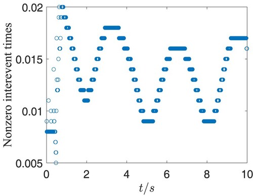
eventually satisfying the practical requirement. The event-triggered torques in the attitude loop are presented in Figures , and they converge to zero after tracking the desired attitude angles. Figures and provide the interevent time
and the threshold of the event-triggered error, from which we can see Zeno behaviour is excluded in the attitude subsystem under the proposed event-triggered control algorithm. In addition, the event-triggered control algorithm in the attitude loop updated 778 times, while 10,000 times' updating is needed if using the traditional time-triggered control algorithm. Thus, the developed adaptive fuzzy trajectory tracking control not only can guarantee the desired control performance, but also can greatly reduce the number of data transmission by
.
Figure 2. The position three-dimensional trajectory tracking curve.
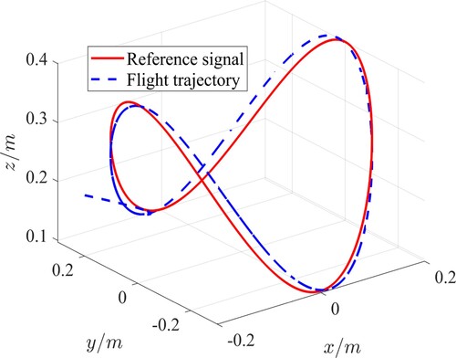
Figure 3. The tracking error of the X axis.
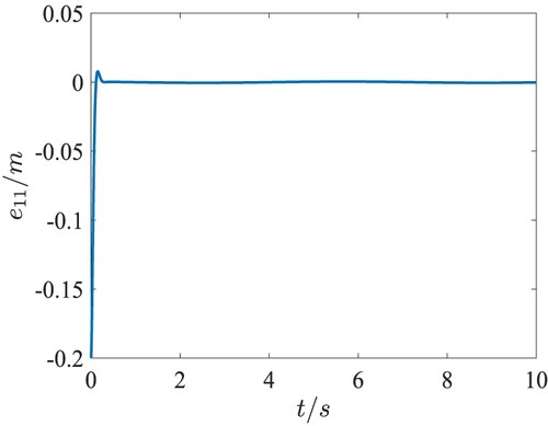
Figure 4. The tracking error of the Y axis.
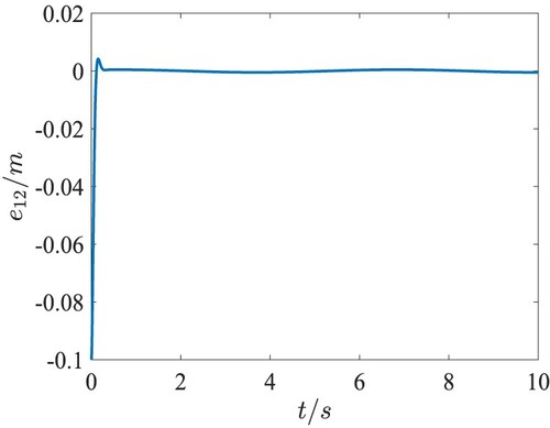
Figure 5. The tracking error of the Z axis.
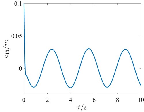
Figure 6. The tracking curve of the yaw angle ψ.
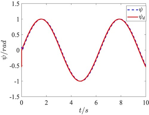
Figure 7. The tracking curve of the pitch angle θ.
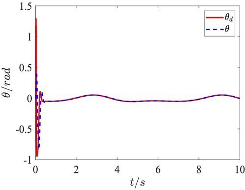
Figure 8. The tracking curve of the roll angle ϕ.
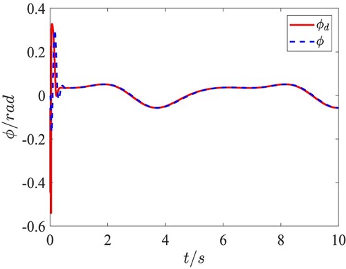
Figure 9. The tracking error of the yaw angle ψ.
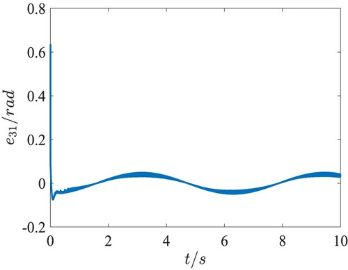
Figure 10. The tracking error of the pitch angle θ.
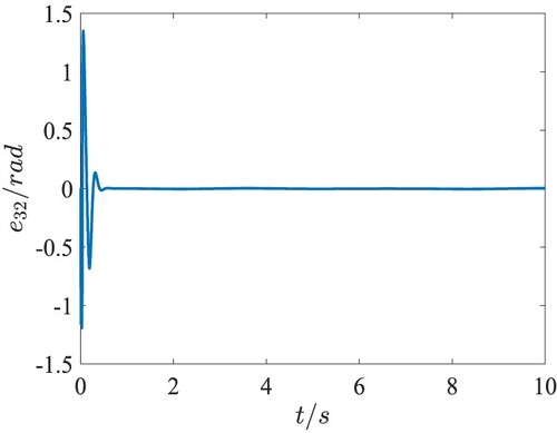
Figure 11. The tracking error of the roll angle ϕ.
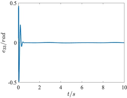
Figure 12. The curve of the control input .
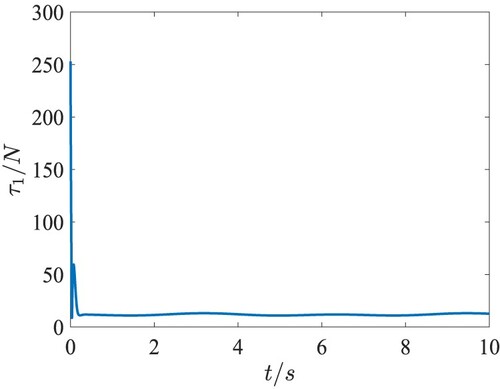
Figure 13. The curve of the control input .
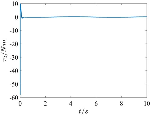
Figure 14. The curve of the control input .
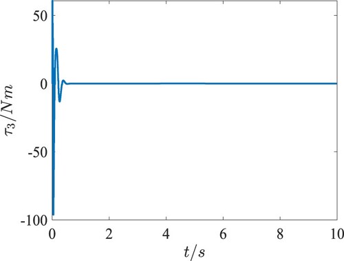
Figure 15. The curve of the control input .
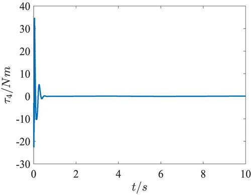
Figure 16. The curve of the event-triggered threshold.
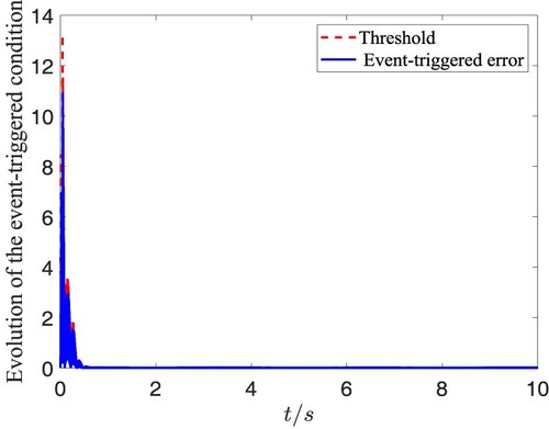
Figure 17. The interval of the triggered time.
7. Conclusion
This article studied the trajectory tracking problem for the QUAV system with model nonlinearity and external disturbances. An adaptive fuzzy control algorithm is applied in the position subsystem to provide desired pitch and roll angles for the attitude subsystem. Then, an adaptive fuzzy event-triggered attitude tracking control algorithm is designed, in which the control law and the parameter adaptive law are updated only when the event-triggered error exceeds the given threshold. It is proven that the trajectory tracking of the QUAV is guaranteed under the developed adaptive fuzzy control algorithm. Moreover, the controller updating times and data transmission are greatly reduced, which improves the utilization of the system resources. Future research includes the dynamic ETC based trajectory tracking of the QUAV system or the ETC based cooperative control of multiple QUAV systems.
Disclosure statement
No potential conflict of interest was reported by the authors.
Additional information
Funding
References
- Adlakha, R., & Zheng, M. H. (2020). An optimization-based iterative learning control design method for UAV's trajectory tracking. In American Control Conference (ACC) (pp. 1353–1359). IEEE.
- Ai, X. L., & Yu, J. Q. (2020). Fixed-time trajectory tracking for a quadrotor with external disturbances: A flatness-based sliding mode control approach. Aerospace Science and Technology, 89(6), 58–76. doi:10.1016/j.ast.2019.03.059
- Antonelli, G., Cataldi, E., Arrichiello, F., Giordano, P. R., Chiaverini, S., & Franchi, A. (2017). Adaptive trajectory tracking for quadrotor MAVs in presence of parameter uncertainties and external disturbances. IEEE Transactions on Control Systems Technology, 26(1), 248–254. https://doi.org/10.1109/TCST.2017.2650679
- Antonio-Toledo, M. E., Sanchez, E. N., Alanis, A. Y., Florez, J. A., & M. A. Perez-Cisneros (2018). Real-time integral backstepping with sliding mode control for a quadrotor UAV. IFAC-PapersOnLine, 51(13), 549–554. https://doi.org/10.1016/j.ifacol.2018.07.337
- Ariffanan, M., & Basri, M. (2018). Trajectory tracking control of autonomous quadrotor helicopter using robust neural adaptive backstepping approach. Journal of Aerospace Engineering, 31(2), 1–15. doi:10.1061/AS.1943-5525.0000804
- Chen, F. Y., Jiang, R. Q., Zhang, K. K., Jiang, B., & Tao, G. (2016). Robust backstepping sliding-mode control and observer-based fault estimation for a quadrotor UAV. IEEE Transactions on Industrial Electronics, 63(8), 5044–5056. https://doi.org/10.1109/TIE.2016.2547365
- Choi, Y. C., & Ahn, H. S. (2015). Nonlinear control of quadrotor for point tracking: Actual implementation and experimental tests. IEEE/ASME Transactions on Mechatronics, 20(3), 1179–1192. https://doi.org/10.1109/TMECH.2014.2329945
- Emam, M., & Fakharian, A. (2016). Attitude tracking of quadrotor UAV via mixed H2/ H∞ controller: An LMI based approach. In Mediterranean Conference on Control and Automation (pp. 390–395). IEEE.
- Li, Q., Alsaadi, F. E., & Alsaadi, F. E. (2020). Dynamic eventtriggered mechanism for H1 non-fragile state estimation of complex networks under randomly occurring sensor saturations. Information Sciences, 509(1), 304–316. https://doi.org/10.1016/j.ins.2019.08.063.
- Li, Q., Wang, Z. D., Li, N., & Sheng, W. G. (2020). A dynamic event-triggered approach to recursive filtering for complex networks with switching topologies subject to random sensor failures. IEEE Transactions on Neural Networks and Learning Systems, 31(10), 4381–4388. https://doi.org/10.1109/TNNLS.5962385
- Li, T. S., Wang, D., Feng, G., & Tong, S. C. (2010). A DSC approach to robust adaptive NN tracking control for strict-feedback nonlinear systems. IEEE Transactions on Systems, Man, and Cybernetics, Part B: Cybernetics, 40(13), 915–927. doi:10.1109/TSMCB.2009.2033563
- Li, Y. X., & Yang, G. H. (2018). Event-triggered adaptive backstepping control for parametric strict-feedback nonlinear systems. International Journal of Robust and Nonlinear Control, 28(3), 976–1000. https://doi.org/10.1002/rnc.v28.3
- Liu, H., Li, D. J., Zuo, Z. Y., & Zhong, Y. S. (2016). Robust three-loop trajectory tracking control for quadrotors with multiple uncertainties. IEEE Transactions on Industrial Electronics, 63(4), 2263–2274. doi:10.1109/TIE.2016.2514339
- Luo, Y. Q., Wang, Z. D., Chen, Y., & Yi, X. J. (2021). H1 state estimation for coupled stochastic complex networks with periodical communication protocol and intermittent nonlinearity switching. IEEE Transactions on Network Science and Engineering, 1–12. doi:10.1109/TNSE.2021.3058220
- Luo, Y. Q., Wang, Z. D., Wei, G. L., & Alsaadi, F. E. (2020). Nonfragile l2−l∞ fault estimation for Markovian jump 2−D systems with specified power bounds. IEEE Transactions on Systems, Man, and Cybernetics: Systems, 50(5), 1964–1975. https://doi.org/10.1109/TSMC.6221021
- Mallavalli, S., & Fekih, A. (2020). A fault tolerant tracking control for a quadrotor UAV subject to simultaneous actuator faults and exogenous disturbances. International Journal of Control, 93(3), 655–668. https://doi.org/10.1080/00207179.2018.1484173
- Özbek, N. S., Önkol, M., & Efe, M. Ö. (2015). Feedback control strategies for quadrotor-type aerial robots: A survey. Transactions of the Institute of Measurement and Control, 38(5), 529–554. doi:10.1177/0142331215608427
- Postoyan, R., Tabuada, P., Nesic, D., & Anta, A. (2015). A framework for the event-triggered stabilization of nonlinear systems. IEEE Transactions on Automatic Control, 60(4), 982–996. https://doi.org/10.1109/TAC.2014.2363603
- Tong, S. C., Wang, T., Li, Y. M., & Zhang, H. G. (2014). Adaptive neural network output feedback control for stochastic nonlinear systems with unknown dead-zone and unmodeled dynamics. IEEE Transactions on Cybernetics, 44(6), 910–921. https://doi.org/10.1109/TCYB.6221036
- Wang, D., & Huang, J. (2005). Neural network-based adaptive dynamic surface control for a class of uncertain nonlinear systems in strict-feedback form. IEEE Transactions on Neural Networks and Learning Systems, 16(1), 195–202. https://doi.org/10.1109/TNN.2004.839354
- Wang, J., Ma, X., Zong, Q., & Wang, D. D. (2019). Trajectory tracking and sliding mode event-triggered control for a quadrotor unmanned aerial vehicle. Control Theory & Application, 36(7), 1083–1089. doi:10.7641/CTA.2018.80149
- Wang, J., Wang, P., & Ma, X. (2020). Adaptive event-triggered control for quadrotor aircraft with output constraints. Aerospace Science and Technology, 105(10), 1–13. doi:10.1016/j.ast.2020.105935
- Wang, N., & Wang, Y. (2018). Fuzzy uncertainty observer based adaptive dynamic surface control for trajectory tracking of a quadrotor. Acta Automatica Sinica, 44(4), 685–695. doi:10.16383/j.aas.2017.c160481
- Wang, N., Wang, Y., & Er, M. joo. (2017). Adaptive dynamic surface trajectory tracking control of a quadrotor unmanned aerial vehicle. Control Theory & Applications, 34(9), 1185–1194. doi:10.7641/CTA.2017.60867
- Xing, L. T., Wen, C. Y., Liu, Z. T., Su, H. Y., & Cai, J. P. (2017). Event-triggered adaptive control for a class of uncertain nonlinear systems. IEEE Transactions on Automatic Control, 62(4), 2071–2076. https://doi.org/10.1109/TAC.2016.2594204
- Xu, Q. Z., Wang, Z. S., & Zhen, Z. Y. (2019). Adaptive neural network finite time control for quadrotor UAV with unknown input saturation. Nonlinear Dynamics, 98(3), 1973–1998. https://doi.org/10.1007/s11071-019-05301-1
- Zhang, J. Q., Gu, D. W., Ren, Z. H., & Wen, B. C. (2019). Robust trajectory tracking controller for quadrotor helicopter based on a novel composite control scheme. Aerospace Science and Technology, 85(2), 199–215. https://doi.org/10.1016/j.ast.2018.12.013
- Zhang, M., Ding, Z. T., Huang, J., & Huang, T. X. (2019). Tracking control for unmanned aerial vehicles with time-delays based on event-triggered mechanism. Control Engineering and Applied Informatics, 21(3), 12–19.
- Zhang, Y., Chen, Z. Q., & Sun, M. W. (2020). Trajectory tracking control for a quadrotor unmanned aerial vehicle based on dynamic surface active disturbance rejection control. Transactions of the Institute of Measurement and Control, 42(12), 2198–2205. https://doi.org/10.1177/0142331220909003
- Zhou, L. H., Zhang, J. Q., Dou, J. X., & Wen, B. C. (2018). A fuzzy adaptive backstepping control based on mass observer for trajectory tracking of a quadrotor UAV. International Journal of Adaptive Control and Signal Processing, 32(12), 1675–1693. https://doi.org/10.1002/acs.v32.12
- Zuo, Z. Y. (2013). Adaptive trajectory tracking control design with command filtered compensation for a quadrotor. Journal of Vibration and Control, 19(1), 94–108. https://doi.org/10.1177/1077546311431270