
 ?Mathematical formulae have been encoded as MathML and are displayed in this HTML version using MathJax in order to improve their display. Uncheck the box to turn MathJax off. This feature requires Javascript. Click on a formula to zoom.
Abstract
In this paper, aiming at the actuator fault-tolerant trajectory tracking problem of two-wheeled differential-driven mobile robots, a super-twisting fractional-order sliding mode fault-tolerant control method combined with a fault observer is proposed. The method not only ensures the pose tracking of the robot in normal condition but also guarantees the tracking performance while the fault occurs. The proposed method mainly includes: A fractional-order sliding mode surface which improves the transient response is utilized to design the fault-tolerant controller, and the super twisting reaching algorithm is adopted to reduce the chattering; A fault observer is designed to estimate the fault value, ensures system stability and safety through real-time compensation. Finally, the proposed fault-tolerant control method is verified by numerical simulation. The results show that the method proposed in this paper can effectively reduce the impact of actuator fault and ensure trajectory tracking performance. And the advantage of the control strategy over the general sliding mode controller is that compared with the integer-order sliding mode control (IOSMC), the fractional-order sliding mode control (FOSMC) we designed in this paper converges all the error states to zero faster, and the tracking error chattering is smaller.
1. Introduction
Due to the remarkable manoeuvrability, flexibility, and dexterity, the application of two-wheeled mobile robots is very wide, and the robot can often be seen in manufacturing, medical care, military, and other industries (Choset, Citation2005). To efficiently fulfil the various complicated practical tasks, a high-performance control strategy needs to be developed for the robot. Thus, the control problem of the wheeled mobile robot has attracted much attention. Many efforts have been devoted to research the tracking problems of wheeled mobile robots in recent years, and scholars have obtained a series of valuable results about the controller design of mobile robots. A variety of intelligent, advanced, and valid control methodologies have been developed, mainly including model predictive control, adaptive control, fuzzy control, neural network control, and sliding mode control (Jin et al., Citation2019; Yang et al., Citation2017; Yazdjerdi & Meskin, Citation2017; Yu et al., Citation2019; Z. Chen et al., Citation2021). In Z. Chen et al. (Citation2021), the adaptive neural networks were used to approximate unknown robot dynamics when the robot parameters are uncertain. The works of (Citation2017; S. Wei et al., Citation2013; Kang et al., Citation2013) considered the robust control scheme for mobile robots in the presence of sideslip and slip. However, in the above-mentioned control method, the robustness and stability of the system need to be further improved, especially consider the faults in the system.
Compared with others, sliding mode control stands out with superior control properties like robustness against the lumped uncertainties and faults, high tracking precision. and in addition, it is simple in design. Therefore, the sliding mode control has been extensively employed in the field of robot control in literature. Researchers have obtained many rich research results, from the most classic linear sliding mode control, to terminal sliding mode control, non-singular terminal sliding mode control (Vo & Kang, Citation2020), fast non-singular terminal sliding mode control (M. Van et al., Citation2019), and integral sliding mode control (J. Lee et al., Citation2017), etc. In X. Yang et al. (Citation2019), an integral sliding mode controller based on a nonlinear disturbance observer was discussed, which enables the mobile robot to achieve trajectory tracking in the presence of external disturbances. In C. Ren et al. (Citation2019), a three-wheeled omnidirectional robot was investigated, based on sliding mode control and the extended state observer techniques, the authors discussed a friction compensation control approach. Although the sliding mode controller is robust to uncertainty, there is an inevitable chattering problem. To reduce chattering, researchers have proposed an exponential reaching algorithm (ERA), and high-order sliding mode technology, such as a super twisting algorithm (STA), and a continuous twisting algorithm.
However, these traditional sliding mode control methods also have many shortcomings, such as slow convergence speed. Thus, the fractional sliding mode has been developed. As a generalization of the traditional integer-order differentiation and integration to non-integer order, the fractional-order theory has been studied by scholars for 300 years as a pure mathematics theory. It is characterized by attenuating old data and storing new data, the data can be used more discriminatively, hence the fractional-order controller is more stable or at least as stable as the integer-order (J. Huang et al., Citation2014; F. M. Zaihidee et al., Citation2019), and has a faster response time. But unfortunately, no one has discovered its actual value until the recent decades and began to be widely applied in science and engineering disciplines.
So far, many controllers have combined fractional order calculus, the most common is the combination of fractional order with classical PID controller indicated as (Dumlu & Erenturk, Citation2014; Viola & Angel, Citation2019). Attracted by the advantages of
controllers, more and more researchers have introduced fractional order calculus in their different controllers, many other fractional controllers have been discovered which includes fractional adaptive controllers (N. Nikdel et al., Citation2016) and FOSMC (J. Huang et al., Citation2014; F. M. Gao et al., Citation2020; Zaihidee et al., Citation2019). Fractional-order (FO) controllers have been widely demonstrated that it has faster convergence and better stability than their IO counterparts. Thus, FO controllers have been broadly applied for complex systems, such as robot manipulators, fractional chaotic systems. FOSMC utilizes fractional calculus in constructing its sliding surface. Compared with the traditional IOSMC, the additional degrees of freedom of the integral and derivative operators of FOSMC can further improve the performance of the controller and FOSMC has many advantages against IOSMC in eliminating system uncertainties and reducing tracking error, and it has less chattering, faster response.
Furthermore, in the process of working, due to the complexity and danger of the work environment, the mobile robot may have a variety of faults (Guo & Chen, Citation2020), and the actuator is a component that is relatively prone to failure. Therefore, how to ensure their reliability and safety is very important to their efficient operation. To minimize the impact of actuator faults on robot performance, fault-tolerant control of the robot is required, which usually has two research directions, and they are active fault-tolerant control and passive fault-tolerant control (Zhang et al., Citation2020). In passive fault-tolerant control, adaptive technology is an effective method to deal with faults (Wang et al., Citation2016). Through the adaptive mechanism, the changes of system parameters and component failures can be quickly estimated. In Ma et al. (Citation2017), they aimed at the actuator failure of the two-link mobile robot and compensates for the failure through adaptive technology. In Z. Shen et al. (Citation2018), they further discussed the robust adaptive fault-tolerant control when the robot actuator fails when the centre of mass is uncertain and there is sideslip and slip. However, the adaptive technology cannot accurately estimate the magnitude of the fault, which is extremely inconvenient for the subsequent maintenance of the robot.
To precisely estimate the effects of faults acting on the robot system, a simple and efficient resolution is to design observers. Observers play a very important role in modern control systems, which make many of the states that cannot be measured by the sensor becomes available, and greatly improves the control performance. In the active fault-tolerant control, the fault information is obtained and estimated by the fault observer which can not only monitor the state of the robot system and provide information for maintenance, but also use the observed fault value as compensation information in the controller to ensure the controller is stable and reliable. Researching this trend, many researchers have been paid attention to develop an effective observer to approximate the faults, numerous observers based on control schemes have been established (W. Chen et al., Citation2016). With the learning ability and high accuracy estimation, the neural network (NN) observer has been widely employed, however, the learning ability makes the system more complicated. The nonlinear disturbance observer is simpler in structure and can estimate the faults with certain accuracy, thus has great advantages in practical applications. (A. T. Vo and H. Kang, Citation2020) use a disturbance observer to estimate uncertain dynamics and faults.
Inspired by the above article, in this study, aiming at the problem of trajectory tracking of mobile robots, considering the possible actuator faults in the actual operation of the robot, we proposed a super-twisting fractional-order sliding mode fault-tolerant control strategy using the fault observer (a nonlinear disturbance observer). Aiming at the shortcomings of the slow transient response of traditional sliding mode control, the fractional-order theory is introduced to design the sliding mode surface. To improve the safety and reliability of the system to resist actuator fault, the FOSMC strategy utilizes the fault information observed by the fault observer to achieve compensation for actuator fault. Aiming at the chattering problem of traditional sliding mode control, we used the STA algorithm to suppress the chattering phenomenon. Due to the utilization of the fractional-order manifold and STA algorithm, faster convergence, better robustness, and smaller chattering and steady-state error are obtained, and due to the compensation of the fault observer, the safety and reliability of the system are guaranteed. The main contributions and innovations of this article are as follows
The dynamic model with the fault of the two-wheel differential mobile robot is established considering the actuator fault. The form of the model is concise and easy to apply.
A fault observer is designed according to the robot model inspired by existing observers to observe the robot fault information, which ensures system stability and safety through real-time compensation.
Compared with the traditional sliding mode controller (C. Azzabi & Nouri, Citation2021; Goswami & Padhy, Citation2018; Ren et al., Citation2019), the fractional-order surface and super twisting algorithm effectively reduce chattering, make the error states converge to zero faster, and the tracking error is smaller, thereby improving the performance of the system.
The rest of this article is as follows. In section II, the basic knowledge of fractional calculus is introduced. In section III, the kinematics and dynamics models of the mobile robot are introduced, and the robot model under fault conditions is established. In section IV, the auxiliary kinematics controller is designed first, then the fault observer is designed based on the robot dynamics fault model, and then the fractional sliding mode fault-tolerant controller is designed based on the dynamics model. In section V, the effectiveness of the fault-tolerant controller is verified by simulation. Section VI gives some conclusions.
2. Preliminaries
To calculate the non-integer order differential and integral of a function, there are currently several methods. This paper uses the Riemann-Liouville method to calculate the value of the fractional integral or differential. The Riemann-Liouville fractional calculus is expressed as follows
Fractional Derivative: The fractional derivative of order
using Riemann-Liouville is defined as (De Oliveira & Tenreiro Machado, Citation2014)
Fractional Integral: The fractional integral of order
3. Kinematics and dynamics model of mobile robot
3.1. Kinematics model of mobile robot
The mobile robot studied in this paper is a two-wheeled differential-driven robot. Its front part is two driving wheels, which are independently driven by a motor, and the rear part is a follower universal wheel, which supports the robot body. The robot is shown in .
Figure 1. Wheeled mobile robot with two independent driving wheels.
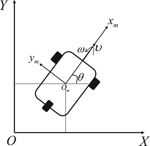
The is the geostationary coordinate system, and the
is the robot body frame. The posture state of the mobile robot in the ground coordinate system
is defined as
,
represents the position of the robot in the global coordinate system, θ is the direction angle of the mobile robot (the angle between the forward direction of the mobile robot and the positive direction of the horizontal axis of the global coordinate system).
and
are the linear velocity and rotational angular velocity along the robot's symmetry axis, respectively.
In the ideal situation, without considering friction and slip, the kinematics model of the mobile robot in the global coordinate system can be expressed as
(3)
(3)
3.2. Dynamic model
According to the analysis of Lagrange mechanics, the dynamic model of the mobile robot can be obtained as
(4)
(4)
where
represents the positive definite inertia matrix,
represents the centrifugal force and the Georgian force matrix.
represents the gravity term of the system,
is the input force transformation matrix, and
represents the input moment vector.
By taking time derivatives of equation Equation(3)(6)
(6) , it yields
(5)
(5)
By taking (5) into (4) and multiply
to the left, it yields
(6)
(6)
According to (Citation2009),
. The robot is moving on the plane, so the gravity term of the system is zero. Therefore, the dynamic model of the robot can be rewritten as
(7)
(7)
where
The control torque of the mobile robot is provided by two DC motors. When the robot actuator fails, the expected output torque is inconsistent with the actual output torque. Generally, the robot actuator failure can be expressed as
(8)
(8) where
represents the actual output when the actuator fails and
is the expected output of the actuator.
is a positive number greater than zero and less than 1.
indicates a time-varying actuator bias fault. When the actuator bias fault exists,
, otherwise,
.
When the robot fails, to facilitate the design of the controller, the dynamic model can be simplified to
(9)
(9)
where
is the composite fault signal, and
is the time when the fault occurs.
4. Design of fault-tolerant controller
According to the established mobile robot model, we carry out the design of the robot controller. Because the actuator may malfunction during the operation of the robot, this is usually reflected in the dynamic model of the robot. To facilitate the design of the controller, the robot controller is designed into two parts: inner loop control and outer loop control. The outer loop controller is a kinematics controller, given the auxiliary linear velocity and angular velocity of the robot movement. The inner loop controller controls the torque to track the output of the outer loop controller. The control block diagram is shown in .
Figure 2. Overall control block diagram.
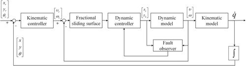
The kinematics controller receives the desired position and angle and the current position and angle
of the robot, determines the linear velocity and angular velocity
, and finally, sends to the fractional sliding surface. The fractional sliding surface receives the auxiliary linear velocity and angular velocity outputted by the kinematics controller and current linear velocity and angular velocity
. The fault observer observes the fault signal according to the previous control quantity
and the current linear velocity and angular velocity
of the robot and sends it to the dynamic controller. The dynamic controller outputs the control quantity
according to the fractional sliding mode surface and the fault observer to control the speed of the robot. As long as the dynamic controller can track the output of the kinematics controller, the robot can reach the desired position. The specific implementation process of each part of the overall control block diagram will be introduced in detail later.
4.1. Kinematics controller
The reference posture of the robot satisfies the following equation if the desired posture of the robot is defined as
(10)
(10)
where
are the linear velocity and angular velocity of the reference trajectory of the mobile robot, respectively. Assuming that the reference velocity and its derivative can be obtained and is bounded, the reference velocity and the reference direction angle can be calculated by the following formula
(11)
(11)
One of the purposes of the research is to make the actual position of the wheeled mobile robot in the working process meet the following requirement
(12)
(12)
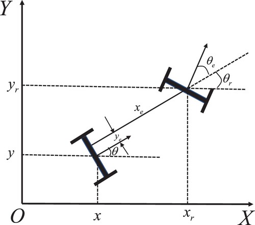
Therefore, the error of the current posture of the mobile robot relative to the expected posture in the robot's body frame can be obtained as
(13)
(13)
where
is the tracking error, which is expressed on the robot body frame, as shown in .
Figure 3. Robot posture error coordinates scheme.
Taking time derivatives of the above equation Equation(13)(17)
(17) and substituting equations Equation(3)
(6)
(6) and Equation(10)
(14)
(14) to obtain the robot error kinematics model
(14)
(14)
Under the new state variables
, the trajectory tracking problem of the mobile robot is transformed into the stability problem of the tracking error model (14).
The auxiliary kinematics controller is designed using the backstepping method as follows
(15)
(15)
where
,
,
are the kinematics controller parameters to be designed, and they are all positive numbers.
Taking the Lyapunov function as
(16)
(16)
Taking time derivatives of the Lyapunov function
, And substituting the kinematics controller (15) into
, it yields
Since the parameters
and
of the WMR kinematics controller are greater than zero, there is
, and
. according to the Lyapunov stability theory, the designed WMR kinematics controller can make trajectory tracking errors converge to zero.
4.2. Dynamic controller
In this subsection, the dynamics fault-tolerant controller is designed according to the dynamic model of the mobile robot. Firstly, considering the design of the fault observation scheme, and making the following assumptions: the fault is bounded, and the differential of the fault is also bounded, namely
(17)
(17)
where
and
are two positive scalars. Because there is no prior knowledge about the actual fault signal community in practical applications, the assumption is a bit strict. However, we can know with certainty that the upper bound of the fault signal exists.
The fault observer is designed as follows
(18)
(18)
where
is the estimated value of the fault,
is the auxiliary variable,
and
are the vector functions to be designed, and satisfies the following relationship
(19)
(19)
From equation Equation(9)
(13)
(13) , it yields
(20)
(20)
Defining the observation error as
The derivation of the above equation can be obtained as
Based on the assumptions about failure, the above equation can be approximated as
(21)
(21)
If the parameters
are selected reasonably, the above equation can be gradually stabilized. The problem is that due to approximate processing, there are requirements for the fault type, and the faults that change too quickly cannot be effectively estimated and there are steady-state errors.
It can be known from the kinematics controller that as long as the robot moves at the designed velocity, it can run along the desired trajectory. However, in the actual system, the robot is often difficult to run at the designed velocity. In the case of an actuator failure, the designed velocity is more difficult to achieve. To guarantee the control performance that will not be greatly attenuated in the presence of a fault, it is necessary to design a dynamic controller ensuring the robot can effectively track the velocity designed by the kinematics controller.
Defining the velocity tracking error vector as
(22)
(22)
According to the fractional-order theory, the following fractional-order sliding mode surface is designed
(23)
(23)
where
is greater than zero.
By taking time derivatives of the sliding mode surface, from (9), (22), and (23), it yields
(24)
(24)
To satisfy the condition of sliding mode condition, the reaching rate of super twisting sliding mode is adopted, and its expression is
(25)
(25)
where
,
,
,
,
is positive numbers and
are sign functions.
The dynamic fault-tolerant controller is designed as
(26)
(26)
is the generalized inverse. To further reduce chattering, an S-type continuous function is used instead of the sign function. The S-type continuous function is
(27)
(27)
Taking the Lyapunov function as
(28)
(28)
By the Lyapunov stability theorem, when
, the system is stable and satisfies the sliding mode reaching condition. Derivation of
can be obtained as
(29)
(29)
By substituting the controller (26) into (29), it yields
(30)
(30)
According to the assumption that the fault is bounded and differentiable, the fault estimation error is also bounded and much smaller than the boundary value of fault. We can choose large enough parameters
to suppress the tracking error. Then
According to the Lyapunov stability theory, thedesigned WMR dynamic controller can finally make the velocity tracking errors converge to zero.
5. Simulation
In this section, to verify the effectiveness of the fault-tolerant trajectory tracking controller designed, the trajectory tracking of the mobile robot is simulated by using the Simulink tool in MATLAB software. The actual physical parameters of the WMR model are: ,
,
,
, where
is the mass of the robot,
is the distance from the driving wheel to the symmetry axis of the robot body,
is the radius of the driving wheel,
is the moment of inertia of the driving wheel.
This paper proposed a fault-tolerant control method based on fractional-order sliding mode control, which corresponds to the integer-order. To compare the performance of these two methods, the integral square error (ISE), integral absolute error (IAE), and time multiplying absolute error integral (ITAE) are used to evaluate the trajectory tracking performance, the expression is as follows
(31)
(31)
where the
is tracking error, the
represents time. These three indicators can reflect the tracking effect from different aspects. The smaller the value, the better the control performance.
The controller parameters are shown in .
Table 1. Controller parameters.
When s, the following fault signals are injected
(32)
(32)
where
.
Case 1: In the first case, the robot has to follow a circle shape in the presence of the actuator fault, the reference velocity is taken as ,
and the expected initial pose is taken as
, the actual initial posture is taken as
, and the initial velocity is taken as
,
.
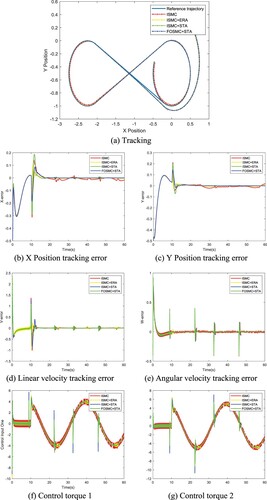
shows the trajectory tracking curve, trajectory tracking error, velocity tracking error, and control torque input of different control methods in the presence of the fault. The ‘ISMC’ represents integer-order integral sliding mode control with isokinetic approaching law, the ‘ISMC + ERA’ represents integer-order integral sliding mode control with exponential reaching algorithm, the ‘ISMC + STA’ represents integer-order integral sliding mode control with the super twisting algorithm, the ‘FOSMC + STA’ represents fractional-order sliding mode control with the super twisting algorithm.
Figure 4. Robot following circle shape trajectory.
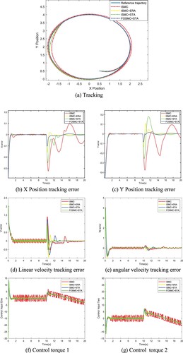
It can be seen that when there is no fault, all the control methods can make the trajectory error and the velocity tracking error quickly approaches zero, the basic requirements of the controller are met.
When s, due to the failure of the actuator, the output of the actuator could not reach the expected output, the trajectory tracking and velocity tracking instantaneously caused a large error. However, due to the introduction of the fault observer, the fault can be compensated to a certain extent. The method proposed in this work can make the tracking error gradually converges to zero again, without further expansion leading to the final divergence. The ‘ISMC + ERA’ and ‘ISMC + STA’ can also do this, but our method has the smallest tracking error, chattering, and overshoot.
(b) and (c) show the position tracking errors, benefiting from fractional-order calculus and super twisting algorithm, it can be seen that regardless of whether there is actuator failure, the tracking error, chattering, and overshoot of ‘FOSMC + STA’ are smallest.
(d) and (e) show the velocity tracking errors, we can get the same conclusion as position tracking errors. in addition, it can be seen that ‘FOSMC + STA’ has a faster response time than others because fractional-order calculus is used in the ddynamics controller to control the velocity of the mobile robot instead of the position, therefore, the characteristic of faster response is shown in the velocity tracking.
(f) and (g) show the control input, it can be seen that due to the performance loss of the actuator, the controller output becomes larger than the value under normal conditions to offset the effect of the actuator failure, which is consistent with our subjective perception.
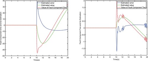
shows the observed effect of the fault observer on the fault. It can be seen that the estimation effect of the fault observer on the fault is not very ideal, and there is a certain error between the estimated value of the fault and the true value. Because some of the assumptions are more stringent. However, this estimation error can be tolerated, and the estimation error is bounded. Due to the robustness of the sliding mode method, this error can be overcome and ultimately ensure the stability of the controller. This has been explained in the stability certificate.
Figure 5. Fault observation performance.
Tables and respectively show the performance index comparison between the ‘ISMC’, ‘ISMC + ERA’, ‘ISMC + STA’ and our ‘FOSMC + STA’ method in position tracking. It can be seen that the FOSMC method designed in this paper achieves better results than the others integer-order control method, almost all indicators are the best.
Table 2. X-axis tracking performance indicators.
Table 3. Y-axis tracking performance indicators.
Case 2: In the second case, the robot has to follow an eight shape path in the presence of actuator fault, the expected initial pose is taken as , the actual initial posture is taken as
, the initial velocity is taken as
,
. the reference velocities
and
are given in .
Table 4. Reference velocities and
in tracking eight path.
The performance of eight shape trajectory tracking is shown in . (a) shows the tracking trajectory. (b) and (c) show the position tracking errors, (d) and (e) show the velocity tracking errors, (f) and (g) show the control input. Same as case one the ‘ISMC’ represents integer-order integral sliding mode control with isokinetic approaching law, the ‘ISMC + ERA’ represents integer-order integral sliding mode control with exponential reaching algorithm, the ‘ISMC + STA’ represents integer-order integral sliding mode control with the super twisting algorithm, the ‘FOSMC + STA’ represents fractional-order sliding mode control with the super twisting algorithm.
Figure 6. Robot following the eight-shape trajectory.
We can see from that there are some differences between tracking eight-shape and tracking circle. after the fault occurs, the tracking error becomes very exaggerated. At the same time, it can be seen from that the fault observer immediately detects the occurrence of the fault and gives the value of fault, due to the use of fault-tolerant control strategies, the tracking error is quickly suppressed and almost converges to zero. The difference is that the tracking error presents periodic changes, and there will be ‘spurs’ in the tracking error within one cycle. This is due to the periodical sudden changes in the angle of the eight-shape, and the controller needs some time to overcome this sudden change. But anyway, we can see that the control method proposed in this article has better control performance, which is manifested in the smallest tracking error and the smallest fluctuation.
Figure 7. Fault observation performance.
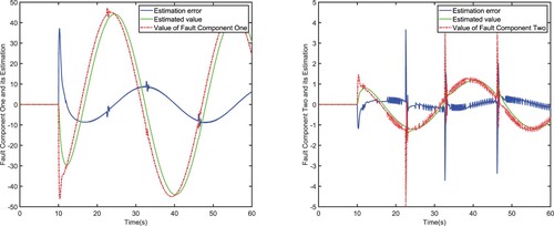
shows the observation result of the actuator fault. It can be seen that the fault observer can observe the value of the fault to a certain extent, but the accuracy needs to be improved.
Tables and respectively show the performance index comparison between the ‘ISMC’, ‘ISMC + ERA’, ‘ISMC + STA’ and our ‘FOSMC + STA’ method in position tracking. In the performance parameters, the smaller the value, the better the performance. From a quantitative perspective, it can also be seen that the method in this article has better performance.
Table 5. X-axis tracking performance indicators.
Table 6. Y-axis tracking performance indicators.
All in all, from the figures and tables, the same conclusion can be drawn as the circular trajectory. But because of the complexity of ‘8’ trajectories, the tracking error fluctuates more. In general, the ‘FOSMC + STA’ has the best tracking performance.
6. Conclusion
For the possible actuator failures of two-wheel differential mobile robots in actual work, this paper proposed a fault-tolerant control strategy based on fault observer and super twisting FOSMC. The validity of the scheme is verified by numerical simulation, after the fault of the faulty actuator occurs, the fault-tolerant controller can respond quickly, reducing the impact of the fault, and restoring the control performance to an acceptable range. Comparing the FOSMC designed in this paper with the IOSMC, the method in this paper has superior performance in the evaluation index.
Data availability
The datasets generated during and/or analysed during the current study are available from the corresponding author on reasonable request.
Disclosure statement
No potential conflict of interest was reported by the author(s).
Additional information
Funding
References
- Azzabi, A., & Nouri, K. (2021). Design of a robust tracking controller for a nonholonomic mobile robot based on sliding mode with adaptive gain. International Journal of Advanced Robotic Systems, 18(1), 172988142098708. https://doi.org/10.1177/1729881420987082
- Chen, C. Y., Li, T., Yeh, Y. C., & Chang, C. C. (2009). Design and implementation of an adaptive sliding-mode dynamic controller for wheeled mobile robots. Mechatronics, 19(2), 156–166. https://doi.org/10.1016/j.mechatronics.2008.09.004
- Chen, M. (2017). Disturbance attenuation Tracking Control for Wheeled Mobile Robots With Skidding and slipping. IEEE Transactions on Industrial Electronics, 64(4), 3359–3368. https://doi.org/10.1109/TIE.2016.2613839
- Chen, W., Yang, J., Guo, L., & Li, S. (2016). Disturbance-Observer-Based control and related methods—An overview. IEEE Transactions on Industrial Electronics, 63(2), 1083–1095. https://doi.org/10.1109/TIE.2015.2478397
- Chen, Z., Liu, Y., He, W., Qiao, H., & Ji, H. (2021). Adaptive-Neural-Network-Based Trajectory Tracking Control for a nonholonomic wheeled mobile robot With velocity constraints. IEEE Transactions on Industrial Electronics, 68(6), 5057–5067. https://doi.org/10.1109/TIE.2020.2989711
- Choset, H. (2005). Principles of Robot Motion: Theory, Algorithms, and Implementations. MIT Press.
- Dumlu, A., & Erenturk, K. (2014). Trajectory Tracking Control for a 3-DOF Parallel Manipulator using fractional-order PIλDμ control. IEEE Transactions on Industrial Electronics, 61(7), 3417–3426. https://doi.org/10.1109/TIE.2013.2278964
- Gao, P., Zhang, G., Ouyang, H., & Mei, L. (2020). An Adaptive super twisting nonlinear fractional order PID sliding mode Control of Permanent Magnet Synchronous Motor speed regulation system based on Extended State observer. IEEE Access, 8, 53498–53510. https://doi.org/10.1109/ACCESS.2020.2980390
- Goswami, N. K., & Padhy, P. K. (2018). Sliding mode controller design for trajectory tracking of a non-holonomic mobile robot with disturbance. Computers & Electrical Engineering, 72, 307–323. https://doi.org/10.1016/j.compeleceng.2018.09.021
- Guo, B., & Chen, Y. (2020). Robust Adaptive Fault-Tolerant Control of four-wheel independently actuated Electric vehicles. IEEE Transactions on Industrial Informatics, 16(5), 2882–2894. https://doi.org/10.1109/TII.2018.2889292
- Huang, J., Lei, C., Shi, X., Li, H., & Xiang, Z. (2014). Composite integral sliding mode control for PMSM. 2014 33rd Chinese control Conference (CCC). IEEE.
- Jin, X. Z., Zhao, Y. X., Wang, H., Zhao, Z., & Dong, X. P. (2019). Adaptive fault-tolerant control of mobile robots with actuator faults and unknown parameters. IET Control Theory and Applications, 13(11), 1665–1672. https://doi.org/10.1049/iet-cta.2018.5492
- Kang, H. S., Kim, Y. T., Hyun, C. H., & Park, M. (2013). Generalized Extended State Observer approach to robust tracking Control for Wheeled mobile robot with Skidding and slipping. International Journal of Advanced Robotic Systems, 10(3), 155. https://doi.org/10.5772/55738
- Lee, J., Chang, P. H., & Jin, M. (2017). Adaptive integral sliding mode control With time-delay estimation for robot manipulators. IEEE Transactions on Industrial Electronics, 64(8), 6796–6804. https://doi.org/10.1109/TIE.2017.2698416
- Ma, Y., Cocquempot, V., Najjar, M. E. B. E., & Jiang, B. (2017). Multidesign integration based Adaptive Actuator Failure compensation control for Two linked 2WD mobile robots. IEEE/ASME Transactions on Mechatronics, 22(5), 2174–2185. https://doi.org/10.1109/TMECH.2017.2731523
- De Oliveira, E. C., & Tenreiro Machado, J. A. (2014). A Review of definitions for fractional derivatives and integral. Mathematical Problems in Engineering, 2014(2), 1–6. https://doi.org/10.1155/2014/238459
- Nikdel, N., Badamchizadeh, M., Azimirad, V., & Nazari, M. A. (2016). Fractional-Order Adaptive Backstepping control of Robotic Manipulators in the presence of model uncertainties and external disturbances. IEEE Transactions on Industrial Electronics, 63(10), 6249–6256. https://doi.org/10.1109/TIE.2016.2577624
- Ren, C., Li, X., Yang, X., & Ma, S. (2019). Extended State Observer-Based sliding mode control of an omnidirectional mobile robot With friction compensation. IEEE Transactions on Industrial Electronics, 66(12), 9480–9489. https://doi.org/10.1109/TIE.2019.2892678
- Shen, Z., Ma, Y., & Song, Y. (2018). Robust Adaptive Fault-Tolerant Control of mobile Robots With varying center of mass. IEEE Transactions on Industrial Electronics, 65(3), 2419–2428. https://doi.org/10.1109/TIE.2017.2740845
- Van, M., Mavrovouniotis, M., & Ge, S. S. (2019). An Adaptive Backstepping nonsingular Fast Terminal Sliding Mode control for robust fault tolerant Control of Robot manipulators. IEEE Transactions on Systems, Man, and Cybernetics: Systems, 49(7), 1448–1458. https://doi.org/10.1109/TSMC.2017.2782246
- Viola, J., & Angel, L. (2019). Delta Parallel Robotic Manipulator Tracking Control using fractional order controllers. IEEE Latin America Transactions, 17(3), 393–400. https://doi.org/10.1109/TLA.2019.8863309
- Vo, A. T., & Kang, H. (2020). A novel fault-tolerant control method for Robot Manipulators based on Non-singular Fast Terminal sliding mode control and disturbance observer. IEEE Access, 8, 109388–109400. https://doi.org/10.1109/ACCESS.2020.300-1391
- Wang, C., Wen, C., & Yan, L. (2016). Adaptive Actuator Failure Compensation for a class of nonlinear Systems With unknown control direction. IEEE Transactions on Automatic Control, 62(1), 385–392. https://doi.org/10.1109/TAC.2016.2524202
- Wei, S., Uthaichana, K., Žefran, M., & DeCarlo, R. (2013). Hybrid model predictive control for the stabilization of wheeled mobile robots subject to wheel slippage. IEEE Transactions on Control Systems Technology, 21(6), 2181–2193. https://doi.org/10.1109/TCST.2012.2227964
- Yang, H., Guo, M., Xia, Y., & Cheng, L. (2017). Trajectory tracking for wheeled mobile robots via model predictive control with softening constraints. IET Control Theory & Applications, 12(2), 206–214. https://doi.org/10.1049/iet-cta.2017.0395
- Yang, X., Wei, P., Zhang, Y., Liu, X., & Yang, L. (2019). Disturbance observer based on biologically Inspired integral sliding mode control for trajectory tracking of mobile robots. IEEE Access, 7, 48382–48391. https://doi.org/10.1109/ACCESS.2019.2907126
- Yazdjerdi, P., & Meskin, N. (2017). Fault tolerant control of differential drive mobile robots using sliding mode controller. 2017 5th International Conference on control, instrumentation, and Automation (ICCIA). IEEE.
- Yu, Z., Zhang, Y., Qu, Y., Su, C. Y., Zhang, Y., & Xing, Z. (2019). Fault-Tolerant Adaptive neural control of multi-UAVs against actuator faults. 2019 International Conference on unmanned aircraft Systems (ICUAS).
- Zaihidee, F. M., Mekhilef, S., & Mubin, M. (2019). Application of fractional order sliding mode control for speed control of Permanent Magnet Synchronous motor. IEEE Access, 7, 101765–101774. https://doi.org/10.1109/ACCESS.2019.293-1324
- Zhang, S., Li, Y., Liu, S., et al. (2020). A Review on fault-tolerant control for robots. 2020 35th youth academic annual Conference of Chinese association of Automation (YAC).