
 ?Mathematical formulae have been encoded as MathML and are displayed in this HTML version using MathJax in order to improve their display. Uncheck the box to turn MathJax off. This feature requires Javascript. Click on a formula to zoom.
Abstract
In the robotic applications, wheel-legged robot provides many advantages such as lightweight, superior performance, low energy consumption and wide development prospects. Especially, in some emergent cases, it has the ability to move flexibly, pass obstacles and work in both outdoor and indoor environment. In this paper, a novel design of wheel-legged platform for robotic investigation is presented. Firstly, the principle diagram of underactuated robot (UR) is outlined owing to the model of inverted pendulum. Then, several theoretical computations are suggested to ensure the ability to work as its desired control. Later, an overview of mechanical design in 3D is described as well as the design of electrical circuit is demonstrated based on these requirements. To validate the feasibility and effectiveness of our approach, several numerical simulations are carried out.
1. Introduction
Mobile robot is a well-known field with great applications, widely deployed from all aspects of daily life, such as vacuum cleaner robot (Amitha et al., Citation2020), home entertainment robot (Wang et al., Citation2020), hotel service robot (Fuentes-Moraleda et al., Citation2020) or patrol robot (Yan et al., Citation2021). At present, mobile robots could be classified into two sub-classes such wheeled and legged robots. Although these developments gain successful outcomes, they are limited in complicated terrains or outdoor environment. Various techniques have been investigated to overcome these problems, i.e. special wheel configuration (Rea & Ottaviano, Citation2018; Zhou et al., Citation2020), passive suspension (Bouton et al., Citation2020; Du et al., Citation2020; Rea & Ottaviano, Citation2018) or specific control (Caicedo et al., Citation2020). Nevertheless, either wheeled or legged robots are not proper for variable terrains but only for specific ones.
For alternative solutions, the underactuated robot becomes an excellent approach. This hybrid configuration combines the benefits of wheels and legs; hence, it could enhance the maneuverability and passing ability on any terrains (Bai et al., Citation2018). With a novel structure of wheels, the wheel-legged robot is able to climb obstacles that are the immense challenges for conventional robots. Traditionally, this type of robot is also known as rotating legs robot (Medeiros et al., Citation2020). Their legs without rim and the movement is mainly based on spokes. The rotating legs significantly simplify the body structure and control method. Many investigations on this theme have been developed, for example, whegs robot (Jiang et al., Citation2019; Kecskés et al., Citation2021; Szczecinski & Quinn, Citation2018), sTetro (Ilyas et al., Citation2018) or transleg (Wang & Lin, Citation2021). However, they trade off the system stability and maneuverability in regular wheeled robot. As a result, there are trends to obtain hybrid configuration between wheel and leg for mobile robot applications. They could be mentioned as tripple wheeled robot (Mertyüz et al., Citation2020), transformable robot with independent motion of wheels and legs (Bruzzone et al., Citation2018). For these reasons, the topics of wheel-legged robot has attracted many researchers and practitioners.
To tackle these troubles that conventional robot meets, a solution for reconfigurable mechanism on mobile robot gains more attentions. It could flexibly change the motion states if wheels or legs are utilized by activating a transformable mechanism. In this means, the method of moving-by-wheel is turned on if robot locates on flat terrain. In the other case, the method of moving-by-leg is triggered if robot stays on rugged terrain. Thanks to the hybrid configuration, the wheel-legged mobile robot is able to decide which motion states are better depending on the terrains.
Recently, a large number of wheel-legged robots has been successfully developed. Fuhar robot (Mertyüz et al., Citation2020) was classified each wheel into three components linked by two joints. Then, driving motors are added to each joint in order to create a flexible actuation. In the same way, the wheels of Lywal robot (Xue et al., Citation2021) are divided into two halves and converted into a leg. The extra actuations that cause more consuming energy and not a compact structure, could be implemented. To avoid the excessive energy consumption, WheeLeR (Zheng & Lee, Citation2019) could alter between wheeled mode and wheel-legged mode by a special trigger device without any motor. The mechanism is based on an unique geared structure, allowing the wheel to transform between two modes, potentially adapting to varying ground conditions. Unlike the extendable radius mentioned above, some other investigators utilize axial push-pull to achieve transformation among working modes. In (Zarrouk & Yehezkel, Citation2018), each circle wheel of robot is splitted into C-shape leg by collapsing two semi-circles along axial direction. Therefore, it can operate either as an equivalent rolling robot or quadruped robot.
2. Background works
In our era, the bio-inspired approach is always proper for robot design. Developers rely on observing the motion of species along with its shape in order to suggest their idea. Commonly, a study on the customs of animal is based on its locomotion. By perceiving a biomimetic approach, it is possible to categorize the modes of locomotion into three main environments such as aerial, marine, and terrain. For each type, it is characterized by the physical principles. depicts an overview of various underactuated robots for different locomotions.
Table 1. An overview of the state-of-art related researches
In several years ago, there are numerous articles in the domain of underactuated robotics. Although it is more complicated than full-drive robot, the underactuated robot has many benefits such as efficient energy-consumption, economical material-usage and requirement of little space (He et al., Citation2019). Generally, there are several classes of underactuated robots which are categorized based on the non-holonomic constraints as well as mechanisms (He et al., Citation2022). To summarize the overall kinds, shortly explains the classifications and mechanisms of URs.
Table 2. Summary of recent studies in underactuated robot
3. Computational design for hybrid mechanism
3.1. Principle diagram
This robot which works in rugged and changeable terrains, under low ground or over obstacles, has a compact design and carry a light cargo. It is maneuverable to operate at low speed for the purposes of exploration and observation. Due to the characteristics of easy manipulation and simple structure, the diagram of a three-wheel vehicle with an active front wheel as is proper with requirements. In addition, when robot goes across complex and unknown terrains, the third self-selecting wheel may be obstructed. Hence, the appropriate design is the three-wheel diagram with two active front wheels. The rear wheel is omitted using a free-slide tail. This slide needs to be implemented with a smooth profile to reduce friction against the ground.
Figure 1. Principle diagram of robot structure.
3.2. Inverted pendulum model
According to the working method of inverted pendulum as , the spinning wheel in foot mode acts as a pendulum model at each step.
Figure 2. Model of inverted pendulum (a) stable position, (b) marginal position, (c) impact position.
It is considered that n is the number of pins on the wheel, and the angle for each pin is computed as below
Whenever robot moves, the vertical displacement is
Movement of each robot leg:
The relationship of velocity between the highest and lowest positions is
In the impact position, a part of the lost energy that causes deformation and is converted to heat, is as following
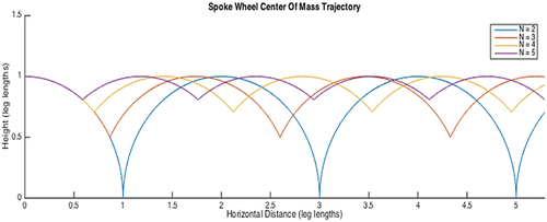
If the number of legs is significantly larger, the center of mass is closer to a straight line, so the undulation is more minor as . At the same time, the values of and
are smaller, therefore robot works more efficient. It is a reason to explain the motion of circular wheel to have the highest efficiency of consuming energy.
Figure 3. The angular trajectory of wheels according to the exchange of legs.
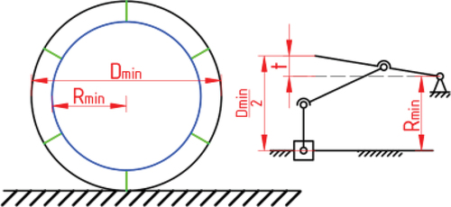
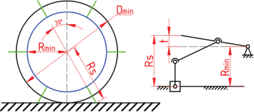
3.3. Off-road ability
If the foot mode is activated, the number of feet would affect on how robot crosses the terrain. Rmin and Rmax are minimum and maximum radius of the swivel foot wheel. Hmax is maximum height of obstacle which wheel could climb over as .
Figure 4. Description for maximum dimensions of obstacle.
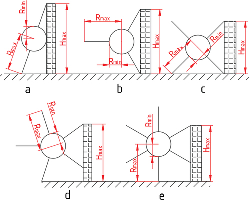
with n = 3,
with n = 4,
with n = 5,
with n = 6,
Generally, the ability to overcome obstacle goes down when the number of legs augments. Nevertheless, the efficiency of consuming energy is higher, and the robot’s motion is smoother and less bumpy when the number of gears increases. On the other hand, because of larger number of legs, it is more difficult to fabricate, and the durability of this mechanism would decrease. As a result, the number of legs in this design is limited to six. The details for the proper election of robot’s legs are evaluated in Appendix A. Besides, the most optimal solution is six feet based on many criteria such as energy loss, obstacle height, and center of mass displacement.
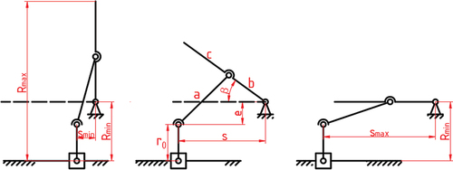
3.4. Analysis of dimensional parameters on wheel-legged
The analysis of dynamic model is illustrated as . Fn is the external force and Fms is the frictional force acting on the wheel. a, b, c, e, r0, Rmin, Rmax are the dimensional parameters of the mechanism structure as .
Figure 5. Analysis of forces when moving.
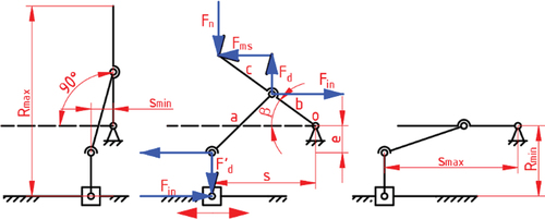
Figure 6. Description for dimensional parameters of wheel.
In fact, some critical items such that the weight of the robot or the angular momentum should be taken into account. Therefore, in the dynamical computation, the number of forces and dimensions must be evaluated.
From , the balancing moment at point O is derived,
where
In case there is only one leg to contact as , the ratio between and
is established as equation (13). Similarly, in the case of two-leg contact, we have
Figure 7. Initial position to move for one-leg contact.
In , simultaneously causes two moments at two legs.
Figure 8. Initial position to move for two-leg contact.
The ratio depends on some parameters such a, b, c, e,
and
where a, b, c and e are the manufacturing parameters,
depends on the terrain surface, and
. It could be seen clearly that this ratio is proportional to
.
It is considered that robot get under the low ground 70 mm. Hence, . Since n = 6, we obtain
. To overcome the obstacle, then
. And
. Later, the dimensional parameters of robot could be chosen as .
Table 3. List of dimensional values for wheel-legged mechanism
In both cases, it is recognized that the ratio peaks at the initial position before climbing, then it decreases gradually and increases slightly near target. In the case of two-leg contact, it requires less forces. Thus, it might be more efficient and consumes less energy.
According to Newton law, the forces or torques at the center point C are as ,
Figure 9. Analysis of forces to overcome the obstacle.
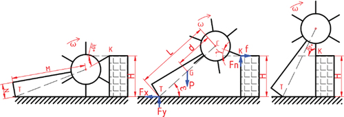
X axis
Y axis
Moment
From the relationship in geometry, we have,
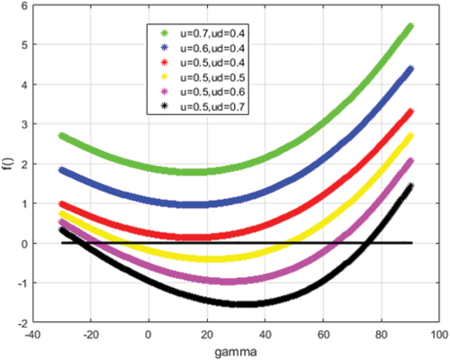
In our tests, the friction coefficient between robot’s leg and ground is approximately . And the coefficient between robot’s tail and ground is about
. Sequently, the function
is studied to validate the slippery phenomenon. These results are shown as .
Figure 10. Result of function when overcoming the obstacle with μ = 0,5, μd = 0,4 and H = 97,5 mm.
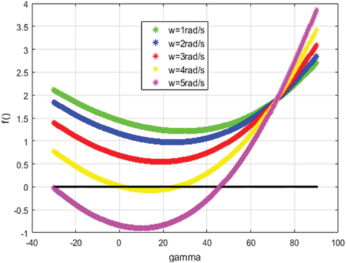
Figure 11. Result of function when overcoming the obstacle with ω = 3,7 rad/s and H = 97,5 mm.
3.5. Mechanical design
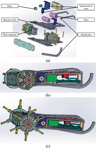
After analyzing and computing the components, in this part, the 3D model is established for the purpose of assembly as ), demonstration of wheel mode as ) and leg mode as ). This design has solved the existing challenges, for example, the problem of reducing impact and increasing friction by covering a rubber pad in the wheel rim. At each top of foot, it is designed a minor groove to attach more rubber cushions which play a significant role in assisting the robot legs to enlarge friction. Thereby, increasing the ability to overcome obstacle could be achieved. Also, it supports robot to reduce the impact on electrical equipment, smoothly operate, extend the life-cycle of the leg structure.
Figure 12. 3D model of hybrid mechanism, (a) component assembly, (b) motion state in wheel mode and (c) motion state in leg mode.
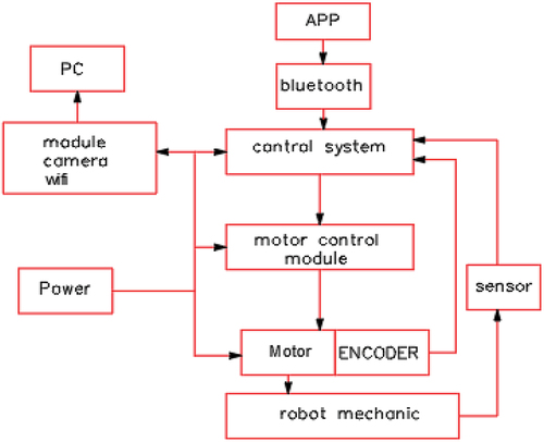
4. Electrical design
In , an overview of electrical connection among components is shown. The APP block which transmits the control signal wirelessly to the bluetooth block placed on the robot body, is the control program from the smartphone. The bluetooth block is the module to receive the wireless control signal and transfer it to the controller. The control system block is the robot’s controller, collects control signals via bluetooth connection. This controller drives the servo motors through the block of motor control. Sensing blocks include sensors that attached on the robot. The power block provides current to both controller and peripheral devices. The wifi camera module is named as CCTV block that captures image data from environment and deliver to host computer (PC block).
Figure 13. Diagram of electrical connection.
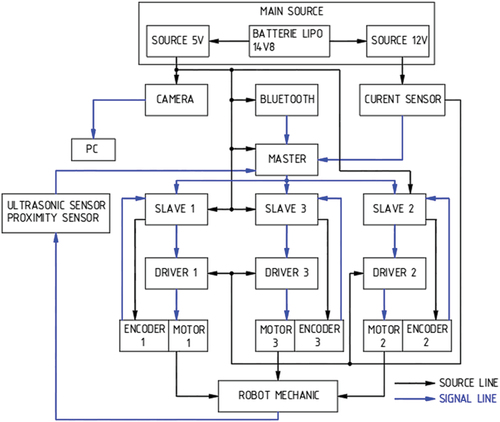
represents an outline of the hierarchical control for the robot system. For the mobility and flexibiliy, robot uses a battery source that is depressurized to 5 V and 12 V levels in two different sources: 12 V power source for the driving motors and 5 V power source for microcontroller, camera, and bluetooth module. Additionally, more sensing devices such as ultrasonic sensor and proximity sensor, are connected in this control scheme.
Figure 14. Diagram of hierarchical control in robot system.
5. Design of control algorithm
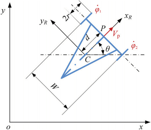
5.1. Analysis of kinetic constraints
We assume that the starting and ending points are and
correspondingly while C is the vehicle’s center of gravity and P is the midpoint of the line between two active axes as . d, W and Rs is the distance between C and P, the width of robot and the turning radius respectively.
are angular rotation between left and right wheel, and horizontal line.
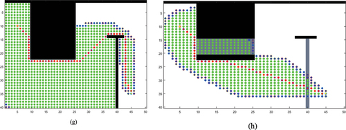
Figure 15. Illustration of kinetic constraints for robot model.
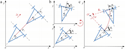
In , different motions such straight movement, turning movement and circular movement are depicted. In detail, each motion must be evaluated in order to drive the servo motor to track the reference trajectory.
Figure 16. Illustration of various motions for robot model.
Case (a) straight movement:
Case (b) turning movement:
Case (c) circular movement with radius Rs:
5.2. Planning strategy
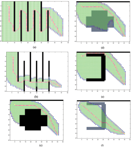
In this paper, the A-star algorithm to find the shortest path is recommended because of its effectiveness and simple implementation. This algorithm would evaluate and select potential paths until the goal is reached. It is assumed that g(n) and h(n) are the cost function of the trajectory from the starting point to the current point and the heuristic function for minimum cost to target point from current point respectively. Then, the sum function f(n) is set as the addition g(n) + h(n). Commonly, if the sum function f(n) is smaller, the point n has the higher priority. The cost of heuristic function h(n) indicate how short the path from the current point to the target point is. We consider that on the map, the colors of flat points, good obstacle points and impassable obstacle points are white, gray and black correspondingly. The cost to move beyond the white point, the black point and the gray point are assumed to be 1, infinity, and 1,378 respectively. The demonstration of the path planning using A* algorithm is performed. In the path of the conventional robot is very long while it is shorter with wheel-legged robot. By assigning a few locations with obstacles that robot could overcome, it would search a new and better trajectory. In , the path of hybrid robot is not affected since the obstacles are dense and the cost of overtaking is excellent. Hence, robot avoids the barriers like as conventional wheel robot. In , the obstacle is not dense, and the cost to overcome is not significant. Therefore, robot decides to utilize its legs to overcome the barriers and choose the shorter and better path. In , it presents the response for two different types of obstacles. Obstacle in front of robot is very dense, consequently robot searches the path of the ordinary wheel to go around. But the second obstacle is small enough for robot to deploy its leg to pass. Totally, the length of trajectory is still shorter than that of regular wheel robot.
Figure 17. Illustration of path planning using A–star algorithm.
In the real-world tests, robot is attached with a global positioning system (GPS) tracking device to attain the current location in relative to the world coordinate on the map as . With modern GPS devices, the tracking accuracy could be less than 3 meters which satisfy most of the industrial requirements. After reaching to the desired area, robot is switched to manual control mode to explore the next target.
Figure 18. Tracking trajectory using the proposed model.
During the tracking process found by the A-star algorithm, robot would scan and detect the unknown obstacles ahead. To assist this work, additional sensing devices such ultrasonic sensors are attached on the hardware body as . The fusing range of these sensors could improve the sensitive ability of detection. For instance, S1 and S2 sensor precisely detect and estimate the both distance and position of an object in the working range of robot while S3 sensor determine whether the obstacle could be overcome or not.
Figure 19. Installation of ultrasonic sensor on robot.
6. Results of research
To validate the proposed design, a test scenario is launched in virtual environment like the real-world application as . It is suggested that robot should be verified in many situations such as static context where the arrangement of objects is in order and chaotic one for any arrangement. In both cases, robot utilizes the same settings of proposed design in hardware platform and planning strategy. In addition, there are several hard obstacles with black colour that robot could not overcome since the height is too high to climb. Otherwise, an object with gray colour indicates that robot could trigger the leg mode to ascend. The motion planning strategy of robot is also forced under the effects of those objects. In common case, the planning scheme easily generates the free trajectory for robot. However, the path candidate could be changed if robot detect the passable obstacles. Subsequently, the working routine of planning strategy is to navigate to target position directly. Whenever detecting an obstacle, robot utilizes its sensors to identify whether it could overcome or not. Then, if this object is possibly surpassed by robot’s leg, it would regenerate the other trajectory toward target position. Otherwise, robot tracks along the profile of obstacle, for example, the autonomous navigation by wall-following scheme, until it comes to next obstacle or free space. This routine is repeated in many cycles while robot navigates in test scenario.
Figure 20. Working map in static context (a) and chaotic one (b).
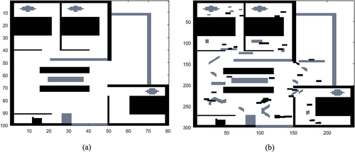
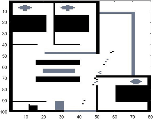
In some complicated cases, robot must deal with the uncertain objects which appear or move in the entire map. It is considered as dynamically planning strategy for the practical situations. In order to represent small unknown obstacles as , the working map is designed to contain actual obstacles with higher resolution, that the size of one unit cell in known map will be equivalently equal to the size of nine unit cells.
Figure 21. Update obstacles after planning by A–star.
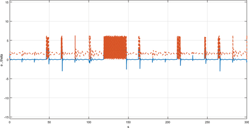
In , red line indicates the desired trajectory found by A-star algorithm in order to ensure the shortest path to target. A blue one performs the real path where robot tries to track as desired line. In reality, the practical trajectory is generated in fluctuated manner since the nonlinear factors exist in hardware. dedicates the tracking results of error and angle while robot navigates in the working map.
Figure 22. Tracking performance of reference trajectory (dash) and actual trajectory (continuous).
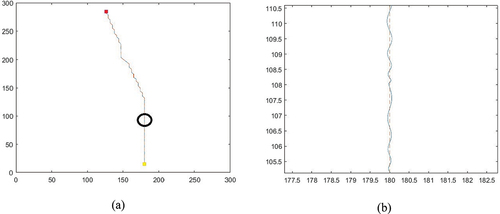
Figure 23. Tracking performance of error (blue) and angle (red).
7. Conclusions
In this paper, a novel design of reconfigurable mechanism for robotic applications is presented. The concept of wheel-legged robot allows the flexible movement in rugged or changeable terrain. To carry out the appropriate design, modeling and computational mechanics ensure the ability to overcome obstacles. The dimensional parameters of robot as well as maximum height of obstacle are identified in 3D design. For the path planning, the A-star algorithm is implemented to search the shortest path. Unlike conventional method, this wheel-legged robot could choose the best trajectory by overcoming obstacles. From these simulation results, it could be seen clearly that the proposed approach is feasible, effective and proper for various applications in rugged or outdoor environment.
Nomenclature
Table
Acknowledgements
We acknowledge the support of time and facilities from Ho Chi Minh City University of Technology (HCMUT), VNU-HCM for this study.
Disclosure statement
No potential conflict of interest was reported by the author(s).
Additional information
Funding
References
- Amitha, S., Raj, P. N., Sonika, H. P., Urs, S., Tejashwini, B., Kulkarni, S. A., & Jha, V. (2020, December). Segregated waste collector with robotic vacuum cleaner using internet of things. In 2020 IEEE International Symposium on Sustainable Energy, Signal Processing and Cyber Security (iSSSC) (pp. 1–25). IEEE.
- Bai, L., Guan, J., Chen, X., Hou, J., & Duan, W. (2018). An optional passive/active transformable wheel-legged mobility concept for search and rescue robots. Robotics and Autonomous Systems, 107, 145–155. https://doi.org/10.1016/j.robot.2018.06.005
- Bouton, A., Grand, C., & Benamar, F. (2020). Design and control of a compliant wheel-on-leg rover which conforms to uneven terrain. IEEE/ASME Transactions on Mechatronics, 25(5), 2354–2363. https://doi.org/10.1109/TMECH.2020.2973752
- Bruzzone, L., Fanghella, P., Berselli, G., & Bilancia, P. (2018, June). Additive manufacturing-oriented redesign of Mantis 3.0 hybrid robot. In International Conference on Robotics in Alpe-Adria Danube Region (pp. 272–280). Springer, Cham.
- Caicedo, J. M. G., Rodríguez, A. B., & Mora, A. A. V. (2020). Suspension effect in tip-over stability and steerability of robots moving on sloping terrains. IEEE Latin America Transactions, 18(8), 1381–1389. https://doi.org/10.1109/TLA.2020.9111673
- Cho, H., Jeong, S. K., Ji, D. H., Tran, N. H., Vu, M. T., & Choi, H. S. (2020). Study on control system of integrated unmanned surface vehicle and underwater vehicle. Sensors, 20(9), 2633. https://doi.org/10.3390/s20092633
- Du, W., Fnadi, M., & Benamar, F. (2020). Whole-body motion tracking for a quadruped-on-wheel robot via a compact-form controller with improved prioritized optimization. IEEE Robotics and Automation Letters, 5(2), 516–523. https://doi.org/10.1109/LRA.2019.2963822
- Fuentes-Moraleda, L., Diaz-Perez, P., Orea-Giner, A., Munoz-Mazon, A., & Villace-Molinero, T. (2020). Interaction between hotel service robots and humans: A hotel-specific Service Robot Acceptance Model (sRAM). Tourism Management Perspectives, 36, 100751. https://doi.org/10.1016/j.tmp.2020.100751
- He, B., Wang, S., & Liu, Y. (2019). Underactuated robotics: A review. International Journal of Advanced Robotic Systems, 16(4) https://doi.org/10.1177/1729881419862164
- He, B., Xu, F., & Zhang, P. (2022). Kinematics approach to energy efficiency for non-holonomic underactuated robotics in sustainable manufacturing. The International Journal of Advanced Manufacturing Technology, 119(1), 1123–1138. https://doi.org/10.1007/s00170-021-08305-7
- Huang, Z., Lai, X., Zhang, P., Meng, Q., & Wu, M. (2020). A general control strategy for planar 3-DoF underactuated manipulators with one passive joint. Information Sciences, 534, 139–153. https://doi.org/10.1016/j.ins.2020.05.002
- Ilyas, M., Yuyao, S., Mohan, R. E., Devarassu, M., & Kalimuthu, M. (2018). Design of sTetro: A modular, reconfigurable, and autonomous staircase cleaning robot. Journal of Sensors, 2018, 1–16. https://doi.org/10.1155/2018/8190802
- Jiang, H., Xu, G., Zeng, W., & Gao, F. (2019). Design and kinematic modeling of a passively-actively transformable mobile robot. Mechanism and Machine Theory, 142, 103591. https://doi.org/10.1016/j.mechmachtheory.2019.103591
- Karásek, M., Muijres, F. T., De Wagter, C., Remes, B. D., & De Croon, G. C. (2018). A tailless aerial robotic flapper reveals that flies use torque coupling in rapid banked turns. Science, 361(6407), 1089–1094. https://doi.org/10.1126/science.aat0350
- Kecskés, I., Odry, A., Tadić, V., & Odry, P. (2021). Simultaneous calibration of a hexapod robot and an IMU sensor model based on raw measurements. IEEE Sensors Journal, 21(13), 14887–14898. https://doi.org/10.1109/JSEN.2021.3074272
- Khan, A. T., Li, S., & Zhou, X. (2021). Trajectory optimization of 5-link biped robot using beetle antennae search. IEEE Transactions on Circuits and Systems II: Express Briefs, 68(10), 3276–3280 https://doi.org/10.1109/TCSII.2021.3062639.
- Medeiros, V. S., Jelavic, E., Bjelonic, M., Siegwart, R., Meggiolaro, M. A., & Hutter, M. (2020). Trajectory optimization for wheeled-legged quadrupedal robots driving in challenging terrain. IEEE Robotics and Automation Letters, 5(3), 4172–4179. https://doi.org/10.1109/LRA.2020.2990720
- Meng, Q., Lai, X., Yan, Z., & Wu, M. (2020). Tip position control and vibration suppression of a planar two-link rigid-flexible underactuated manipulator. IEEE Transactions on Cybernetics, 1–13. https://doi.org/10.1109/TCYB.2020.3035366
- Mertyüz, İ., Tanyıldızı, A. K., Taşar, B., Tatar, A. B., & Yakut, O. (2020). FUHAR: A transformable wheel-legged hybrid mobile robot. Robotics and Autonomous Systems, 133, 103627. https://doi.org/10.1016/j.robot.2020.103627
- Nguyen, S. T., & La, H. M. (2021). A climbing robot for steel bridge inspection. Journal of Intelligent & Robotic Systems, 102(4), 1–21. https://doi.org/10.1007/s10846-020-01266-1
- Phan, H. V., & Park, H. C. (2019). Insect-inspired, tailless, hover-capable flapping-wing robots: Recent progress, challenges, and future directions. Progress in Aerospace Sciences, 111, 100573. https://doi.org/10.1016/j.paerosci.2019.100573
- Rafsanjani, A., Zhang, Y., Liu, B., Rubinstein, S. M., & Bertoldi, K. (2018). Kirigami skins make a simple soft actuator crawl. Science Robotics, 3(15), eaar7555. https://doi.org/10.1126/scirobotics.aar7555
- Rea, P., & Ottaviano, E. (2018). Design and development of an inspection robotic system for indoor applications. Robotics and Computer-Integrated Manufacturing, 49, 143–151. https://doi.org/10.1016/j.rcim.2017.06.005
- Romano, D., & Stefanini, C. (2021). Unveiling social distancing mechanisms via a fish-robot hybrid interaction. Biological Cybernetics, 115, 565–573. https://doi.org/10.1007/s00422-021-00867-9
- Sahoo, A., Dwivedy, S. K., & Robi, P. S. (2019). Advancements in the field of autonomous underwater vehicle. Ocean Engineering, 181, 145–160. https://doi.org/10.1016/j.oceaneng.2019.04.011
- Shavarani, S. M., Nejad, M. G., Rismanchian, F., & Izbirak, G. (2018). Application of hierarchical facility location problem for optimization of a drone delivery system: A case study of Amazon prime air in the city of San Francisco. The International Journal of Advanced Manufacturing Technology, 95(9), 3141–3153. https://doi.org/10.1007/s00170-017-1363-1
- Szczecinski, N. S., & Quinn, R. D. (2018). Leg-local neural mechanisms for searching and learning enhance robotic locomotion. Biological Cybernetics, 112(1), 99–112. https://doi.org/10.1007/s00422-017-0726-x
- Wang, Z., Tian, G., & Shao, X. (2020). Home service robot task planning using semantic knowledge and probabilistic inference. Knowledge-Based Systems, 204, 106174. https://doi.org/10.1016/j.knosys.2020.106174
- Wang, T. H., & Lin, P. C. (2021). A reduced-order-model-based motion selection strategy in a leg-wheel transformable robot. IEEE/ASME Transactions on Mechatronics, 1–7. https://doi.org/10.1109/TMECH.2021.3126606
- Wu, Y., Yao, D., & Xiao, X. (2018). The effects of ground compliance on flexible planar passive biped dynamic walking. Journal of Mechanical Science and Technology, 32(4), 1793–1804. https://doi.org/10.1007/s12206-018-0336-0
- Xue, Y., Yuan, X., Wang, Y., Yang, Y., Lu, S., Zhang, B., … Xiao, X. (2021, May). Lywal: A leg-wheel transformable quadruped robot with picking up and transport functions. In 2021 IEEE International Conference on Robotics and Automation (ICRA) (pp. 2935–2941). IEEE.
- Yan, D., Cao, H., Wang, T., Chen, R., & Xue, S. (2021). Graph-based knowledge acquisition with convolutional networks for distribution network patrol robots. IEEE Transactions on Artificial Intelligence, 2(5), 384–393. https://doi.org/10.1109/TAI.2021.3087116
- Zarrouk, D., & Yehezkel, L. (2018). Rising STAR: A highly reconfigurable sprawl tuned robot. IEEE Robotics and Automation Letters, 3(3), 1888–1895. https://doi.org/10.1109/LRA.2018.2805165
- Zhang, P., Lai, X., Wang, Y., Su, C. Y., & Wu, M. (2018). A quick position control strategy based on optimization algorithm for a class of first-order nonholonomic system. Information Sciences, 460, 264–278. https://doi.org/10.1016/j.ins.2018.05.054
- Zheng, C., & Lee, K. (2019, May). WheeLeR: Wheel-leg reconfigurable mechanism with passive gears for mobile robot applications. In 2019 International Conference on Robotics and Automation (ICRA) (pp. 9292–9298). IEEE.
- Zhou, X., He, J., He, Q., Ren, C., He, M., & He, M. (2020). Motion kinematics analysis of a horse inspired terrain-adaptive unmanned vehicle with four hydraulic swing arms. IEEE Access, 8, 194351–194362. https://doi.org/10.1109/ACCESS.2020.3033148
Appendix A
To adapt with various obstacles and different terrains, the conditions to elect the number of legs n depend on the minimization of the vertical displacement ∆H and its loss energy Eloss while Hmax is large. Thus, the criteria TC to select the proper solution is
From equation (6) to (10), the ability to climb would be decreased when the number of legs n increases, but the effective energy is better and the motion of robot is smoother. Additionally, the large number of legs n could cause some difficulties in manufacturing and poor structural strength. Hence, in the scope of this research, the number of legs n should be limited to six (n ≤ 6).
Substituting Equationequation (2)(2)
(2) and (Equation5
(5)
(5) ), then equation (A.1) becomes
For each case, the number of legs n varies from 2 to 6 as follow
From those computations, it could be seen clearly that robot should have six legs for the proper design.