?Mathematical formulae have been encoded as MathML and are displayed in this HTML version using MathJax in order to improve their display. Uncheck the box to turn MathJax off. This feature requires Javascript. Click on a formula to zoom.
Abstract
The human foot structure has been evaluated, especially on its contribution to stable bipedal locomotion. This paper presents a bevel-geared mechanical bioinspired robotic foot that emulates the rotational motions of the human subtalar and oblique midtarsal joints. The motions generate a yaw moment at touch-down and may contribute to suppressing yaw rotation of the whole body. We develop a musculoskeletal biped robot equipped with feet and conduct walking experiments to measure the generated yaw moment during walking. Experimental results demonstrate that the peak of the yaw moment and the amplitude change of the torso yaw rotation significantly decrease by 41.4% and 13.0% with the geared foot, respectively. This study proposes a mechanical design for reducing the yaw moment and whole-body rotation of a bipedal walking robot without complicated control.
GRAPHICAL ABSTRACT
1. Introduction
During bipedal walking, yaw moment is inevitably generated at the support foot due to the acceleration and deceleration of the swing leg [Citation1–3]. For stable walking, it must be counterbalanced [Citation1]. Large yaw moments cause the support foot to slip easily and the robot becomes unstable [Citation2,Citation4]. Because the yaw moment increases with the walking velocity, it has a great effect on fast walking [Citation1,Citation5]. To suppress this yaw moment, conventional methods carefully control the upper body motion to generate the contrary yaw moment. For example, the arm swing motion is effective for yaw moment reduction in humans [Citation6,Citation7] and is widely applied to bipedal walking robots [Citation4,Citation8]. The yaw rotational movement of the torso can reduce the moment as well [Citation2,Citation5,Citation9].
In recent years, some studies have suggested that the human foot structure has high potential in improving the performance of bipedal locomotion through embodied intelligence [Citation10] without complicated control [Citation11–16]. The medial longitudinal arch with elastic plantar fascia can absorb the impact [Citation13], adapt to uneven terrain [Citation11], and make the robot jump higher [Citation14]. The bioinspired robotic foot with the oblique joint can be applied to reduce the torso's rolling during walking [Citation15]. A recent study suggested that the structural motion of the oblique joint can reduce the yaw moment in bipedal walking [Citation16].
This paper describes the design of a bioinspired robotic foot with a bevel-geared mechanism that emulates the rotational motions of the human subtalar joint (STJ) and oblique midtarsal joint (OMTJ). The motions of these two joints are supposed to generate the moments to mechanically compensate the yaw moment, which is generated at the support foot during bipedal walking. The yaw rotation of the robot's torso is suppressed by the yaw moment, accordingly.
In the human foot, the STJ and OMTJ are two main oblique joints [Citation17,Citation18]. Their rotational motions affect the yaw moment generation during bipedal walking [Citation16,Citation19, Citation20]. It is difficult and not practical to completely clone the structures of these two joint to design the robotic foot [Citation12]. According to functional anatomical reports on the human foot [Citation21–24], the interlocking rotational movements of STJ and OMTJ can be partially simplified using the motion of the bevel-geared mechanism [Citation25].
We developed a bioinspired robotic foot with a mechanism composed of three bevel gears. To compare the generation of the yaw moment under the conditions of with/without the developed mechanism during the robotic bipedal walking, we also built a rigid foot as a comparative base in the experiment. The rigid foot and bevel-geared foot were equipped on a developed musculoskeletal bipedal walking robot, and the robotic bipedal walking experiment is conducted. The yaw moment and torso yaw rotation were measured by a force plate and a motion capture system.
The results show that the bevel-gear foot significantly decreases 41.4% of the internal peak of the yaw moment during the first half of the stance phase. In the torso yaw rotation result, the bevel-geared mechanical foot significantly decreases the amplitude by 13.0% during the stance phase. This study proposes a novel application for the bioinspired robotic foot design and also highlights the importance of the human foot morphology.
2. Development of the bevel-geared mechanical foot
2.1. Bevel-geared mechanical foot
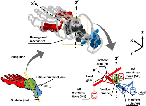
The design of the bevel-geared mechanical foot is illustrated in Figure . The left side of Figure illustrates the STJ and OMTJ of the human foot. They both form the oblique axis [Citation17,Citation18]. These joints allow the foot to move in triplane motion; pronation/supination. These movements are mainly generated by the coupling force of the body weight and ground reaction force, which apply to the human foot bones [Citation21,Citation26]. The STJ and OMTJ allow the hindfoot and forefoot to rotate simultaneously and adapt the rotation of each other [Citation21–24,Citation27,Citation28]. The STJ allows the hindfoot to pronate during the first half of stance phase (i.e. from initial contact to midstance phases) and spinate during the latter half (i.e. form midstance to toe-off phases) [Citation27,Citation29]. Meanwhile, the OMTJ allows the forefoot to supinate during the first half of stance phase and pronate [Citation18,Citation27,Citation30]. In biomechanics study, this combinational movement is represented by the lamina pedis model [Citation24]. The motion of the STJ also drives the talus to compensate for the rotation of the tibia in the transverse plane [Citation31]. In this study, we focus on mimicking and utilizing the rotational motions of the STJ and OMTJ in the transverse and frontal planes (i.e. the rotations of the yaw and roll axes). The motions of the pronation/supination in the transverse and frontal planes are abduction/adduction and eversion/inversion. Following the mechanical model of the human foot [Citation22,Citation23], the twisted plate model [Citation24,Citation27], the anatomical functions reports [Citation17,Citation18,Citation32], equilibrium theory [Citation21], and mechanical mechanism design, we use the bevel gears to simplify the structures of the STJ and OMTJ. The structural simplification is shown in the middle of Figure . To generate the rotation, the moment arm has to be considered. The moment arms of the STJ and OMTJ change with to the deformation of the bones of the human foot during walking. Owing to the challenge of realizing this complex variable structure, we assume that the moment arms of the STJ and OMTJ are fixed in this study. The right side of Figure illustrates the kinematic diagram of the bevel-geared mechanical foot.
Figure 1. Conceptual design of the bevel-geared mechanical foot. The left lower side shows the human foot structure and subtalar and oblique midtarsal joints. The middle shows the structural simplification of the human foot to bevel-geared mechanical foot. The right lower side shows the kinematic diagram of the bevel-geared mechanical foot. The blue, green, and red parts represent the hindfoot, talus, and forefoot, respectively. The and
represent the rolling and yawing axes of the robotic foot, respectively
2.2. Yaw moment generation
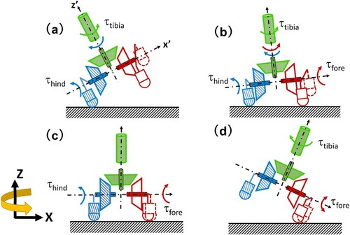
The designed motion and yaw moment generation procedure of the bevel-geared mechanical foot are illustrated in Figure . At the initial contact phase, the heel contacts the ground; owing to the coupling force generated by the ground reaction force and body weight, the hindfoot starts to evert and generates the hindfoot moment () and external yaw moment at the vertical joint (VJ). This external yaw moment suppresses the generation of the internal yaw moment of the tibia (
). Additionally, because of the transmission of the bevel-geared mechanism, the forefoot inverts simultaneously. At the loading response phase, owing to the inversion at the previous phase, the fifth metatarsal bone starts to land on the ground first and causes the forefoot to evert and generate the forefoot moment (
) and yaw moment at the vertical joint to counterbalance the yaw moment, which is generated by the hindfoot. At the midstance phase, the heel, first metatarsal, and fifth metatarsal bones land on the ground. Owing to the bevel-geared mechanism, the moments of the hindfoot and forefoot lock the vertical joint to support the lower limb. At the heel-off phase, because the moment arms of the first and fifth metatarsal bones are similar, the forefoot generates a moment (
) to continually lock the bevel-geared mechanism and support the lower limb. By this process, the designed robotic foot produces a contrary yaw moment to suppress the generation of the internal yaw moment of the tibia, reduce the rotation of the torso during the first half of the stance phase, and support the lower limb at the latter half of the stance phase.
Figure 2. The movements and yaw moment generation process during the stance phase of the bevel-geared mechanical foot. This figure shows the x–z plane view. (a) Initial contact phase, (b) loading response phase, (c) midstance phase, (d) heel-off phase. Where the ,
, and
represent the generated moments of the hindfoot, forefoot, and tibia, respectively. The
and
represent the rolling and yawing axes of the robotic foot, respectively.
2.3. Hardware design
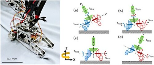
Following the above development concepts, the bioinspired bevel-geared mechanical foot is developed. It is illustrated in Figure . The configuration of bevel-geared foot is shown in Figure . This foot has four parts; the forefoot, talus, gear mechanism, and hindfoot. It has four joints and two degrees of freedom. The bevel-geared mechanism integrates the three joints, the hindfoot, forefoot, and vertical joints, and provides one degree of freedom to realize the interlocking rotational moments. The hindfoot and forefoot joints allow the hindfoot and forefoot to evert/invert. The vertical joint connects the talus to drive it to internally/externally rotate. At the talus, it has a joint, which is functionally equivalent to the human talocrural joint (i.e. ankle joint). It allows the foot to dorsiflex/plantarflex. The length and height of this foot are 210 mm and 149 mm, respectively Its heel and forefoot are 27 mm and 107 mm in width, respectively. The weight of the foot is 1.39 kg. To make the hindfoot and forefoot rotate when the ground reaction force is applied on the heel and the contact point of the forefoot, the moment arms of the hindfoot and forefoot are 25 mm and 45 mm, respectively. We referred to the average length of subtalar joint moment arm (i.e. approximately 23 mm) [Citation33] and the foot breadth horizontal length (i.e.approximately 91.4 mm) [Citation34], the biomimicking robotic foot designs [Citation15,Citation16] and the empirical tests to determine the moment arms of the hindfoot and forefoot and the size of the bevel-geared mechanical foot. The empirical tests are the robot's body supporting and robotic bipedal walking. The bevel-geared mechanism is composed of three bevel gears (KHK Co. SMB2-25) and illustrated in the right side of Figure . The interlocking movement of the robotic foot is shown in the supplementary video of S1-GearFoot-movements. According to the anatomy investigation, the moving ranges of the eversion and inversion of the human foot are 20 and 30
, respectively [Citation35]. The limitation of eversion and inversion ranges of the bevel-gear foot is the same as the findings of the human foot. This limitation is realized by two movement limiting plates (Figure (b)).
Figure 3. The bevel-geared mechanical foot (right foot) and the bevel-geared mechanism.
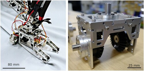
Figure 4. Configuration and corresponding relationship with human foot of bevel-geared mechanical foot. This figure shows the right foot. The green, blue, red, and gray parts represent the talus, hindfoot, forefoot, and bevel-geared mechanism, respectively. The VJ, HJ, FJ, M1, and M5 represent the vertical joint, hindfoot joint, forefoot joint, first metatarsal bone, and fifth metatarsal bone, respectively.
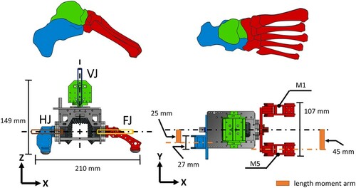
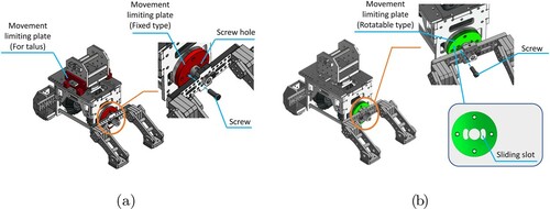
Figure 5. The tested feet, (a) Rigid foot, (b) Bevel-geared mechanical foot.
3. Robotic bipedal walking experiment and results
The purpose of this experiment was to examine the performance of the test feet on a biped walking robot. We measured the yaw moment and torso yaw rotation during the stance phase of the developed musculoskeletal biped walking robot.
3.1. Setup of the biped walking experiment
3.1.1. Comparative conditions
To conduct the comparative experiment with/without the bevel-geared foot mechanism, we made two tested feet for the comparative conditions. The detailed design purposes are listed below.
Rigid foot condition (a): Foot without the bevel-geared mechanism
Bevel-geared foot condition (b): Foot with the bevel-geared mechanism
The rigid foot is illustrated in Figure . The rigid foot weighed 1.42 kg. The rigid foot condition is built using the bevel-geared mechanical foot, aluminum plates, and screws. At the two sides of the talus, the two aluminum movement limiting plates fix the vertical joint and prevent the vertical rotation of the talus. The screws are used to fix all the joints of the bevel-geared mechanical foot. The difference between the rigid and bevel-geared feet is the bevel-geared foot was installed in the rotatable movement limiting plate and without the talus limiting plate.
3.1.2. Musculoskeletal biped walking robot
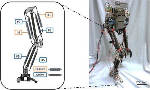
In the experiment, we installed the rigid foot and bioinspired robotic foot on the developed musculoskeletal biped walking robot. Figure illustrates the musculoskeletal biped walking robot and its setup of the pneumatic artificial muscle (PAM). This musculoskeletal biped walking robot weighed 6.2 kg, was 1 m tall, and 0.31 m wide, with a length of 0.16 m. Each leg had a hip, knee, and ankle joints (i.e. the talocrural joints of the test robotic feet), which were actuated by antagonistic movements [Citation36]. To clearly observe the contributions of the test feet, the hip and knee joints of the walking robot were only allowed for flexion/extension. To simplify the control sequence and implement antagonistic movements, only the gluteus maximus (#2), vastus lateralis (#3), tibialis anterior (#5), and soleus (#6) in this robot were equipped with the PAMs. The other muscles were equipped with springs. The diameter of the inner tube of the PAMs was 10 mm. The lengths of the gluteus maximus, vastus lateralis, tibialis anterior, and soleus were 150, 230, 210, and 210 mm, and the stiffness of the tibialis anterior and iliacus were all 6.4 N/mm. The operational pressure in this experiment was 0.6 MPa. For the robot to walk, we created a simple control pattern to control the PAMs to drive the legs. The detailed content of the control pattern is shown in the appendix.
Figure 6. Musculoskeletal biped walking robot and muscle setup. #1–#6 represent Iliacus, Gluteus maximus, Vastus lateralis, Popliteus, Tibialis Anterior, and Soleus muscles, respectively.
3.1.3. Experimental environment and data measurement
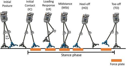
The experimental environment and walking procedure are shown in Figures and . The robot was initially held by the experimenter and the left leg was raised by approximately 20 (Initial posture phase) and subsequently released. It stepped forward and made contact with the force plate. The yaw moment during the single support phase was measured using the force plate.
Figure 7. Environment for the walking experiment. Int+ and Ext- represent internal and external rational directions, respectively.
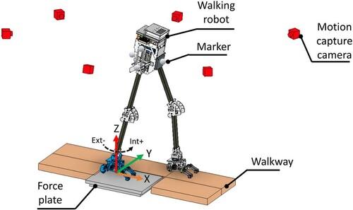
Figure 8. Walking procedure. The blue foot represents right foot.
In this study, the yaw moment is measured by a force plate (Tec Gihan Co., Ltd., TF-3040) in the walking experiment. The experiments were conducted using the right foot, and the measurement coordinate system is shown in Figure . The sampling rate was 1 kHz. To determine the contact timing of each part of the robotic foot, we measured the rotations of the bevel-gear foot. We installed a magnetic rotary position sensor (ams AG Co., AS5600) at the hindfoot joint. The sampling rate was 100 Hz. We used a motion capture system which is included the tracking software (OptiTrack Co. Motive Tracker) and six cameras (OptiTrack Co., Flex 13) to measure the torso yaw rotation of the bipedal walking during the stance phase. The sampling rate was 100 Hz.
3.1.4. Statistical method and data analysis
The yaw moment results were filtered using a 4th order low-pass Butterworth filter with a 15 Hz cutoff frequency [Citation16]. The foot rotational angle and torso rotation results were filtered using the same filter with a 5 Hz cutoff frequency. The filter was programmed using python and integrated the Scipy and Pandas libraries. The results of internal rotation pecks and torso yaw rotational amplitude changes were tested by using Wilcoxon rank sum test (p<0.01). It was processed using R language.
3.2. Experimental results
Figures and illustrate the measurements of the yaw moment. The timing of the phase of gait in each condition was different. The initial contact phases (IC) of the rigid and bevel-geared feet all occurred at 0% of the stance phase. The loading response phases (LR) of the rigid and bevel-geared feet occurred at approximately 27.8% and 30.6% of the stance phase, respectively. The midstance phases (MSt) of the rigid and bevel-geared feet occurred at approximately 39.7% and 42.2% of the stance phase, respectively. The heel-off phases (HO) of the rigid and bevel-geared feet occurred at approximately 55.32% and 60.2% of the stance phase, respectively. The toe-off phases (TO) of the rigid and bevel-gear feet occurred at approximately 94.7% and 95.2% of the stance phase, respectively.
Figure 9. Yaw moments during the robot walking experiment. The blue and red lines are the averages of the rigid foot and bevel-geared mechanical foot; the light blue shadows are the standard deviation variability bands. The n represents the number of trials, (a) Rigid foot, (b) Bevel-geared mechanical foot.
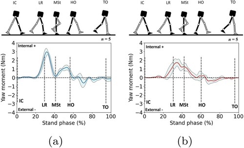
Figure 10. Internal yaw moment peaks. The labels of Rigid and Gear represent the rigid foot and bevel-geared mechanical foot, respectively. ** represent p<0.01.
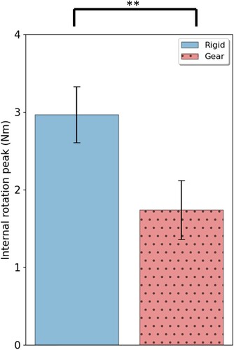
The internal rotation peaks of the yaw moment of the rigid and bevel-geared feet occurred at approximately 31.8% and 34.5% of the stance phase, respectively. The average values of the peak of the rigid and bevel-geared feet were Nm and
Nm, respectively. The value for the bevel-geared foot was approximately 41.4% lower than that of the rigid foot.
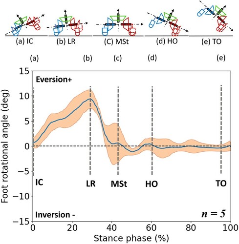
The rotations of the bevel-geared foot in the robotic walking are shown in Figure . The average value was calculated by measurements across five experiments on each foot. The peak amplitudes of the eversion and inversion of the hindfoot were approximately and
, respectively
The torso yaw rotation results are shown in Figures and . The average value is calculated by measurements across five experiments on each foot. With the rigid foot, the robot rotated from approximately 3.5 to 26.1
. With the bevel-geared foot, the robot rotated from approximately 2.8
to 21.7
. The amplitude changes of the rigid foot and bevel-geared foot were
and
, respectively. The bevel-geared foot was approximately 13.0% lower than the rigid foot. These amplitude changes of the tested feet were calculated by the minimum and maximum magnitude of the torso yaw rotational angles.
Figure 11. Torso yaw rotation in the robotic bipedal walking. The blue and red lines are the averages of the rigid foot and bevel-geared mechanical foot; the light blue shadows are the standard deviation variability bands. The n represents the number of trials, (a) Rigid foot, (b) Bevel-geared mechanical foot.
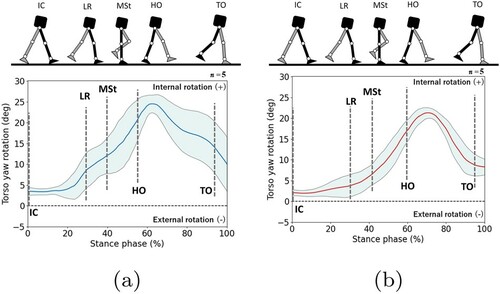
Figure 12. Amplitude change of torso yaw rotation. The labels of Rigid and Gear represent the rigid foot and bevel-geared mechanical foot, respectively. ** represent p<0.01.
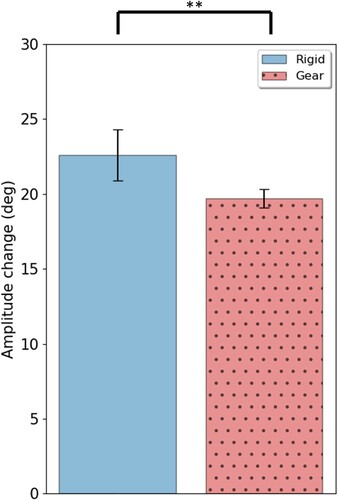
Figure 13. Rotational angle of the bevel-geared mechanical foot. The blue line is the average; the orange shadows are the standard deviation variability bands. The n represents the number of trials.
4. Discussion
This study developed a robotic foot equipped with a bevel-geared mechanism that mimics the rotations of the subtalar and oblique midtarsal joints to passively suppress the yaw moment generated at the support foot and reduce the torso yaw rotation of the robot during the stance phase walking.
In the yaw moment results, the rigid and bevel-geared feet both exhibited the significant internal yaw moment peak at the first half and the external yaw moment peak at the latter half of the stance phase. The rigid foot and robot's hip and knees have no mechanism or structure to directly affect the yaw moment's generation. Therefore, the resulting yaw moment of the rigid foot can be regarded as that is generated by the torso rotation induced by the swing leg's motion. The internal yaw moment peak of the bevel-geared foot was significantly smaller than that of the rigid foot. This result suggests that the bevel-geared foot suppressed the yaw moment generation. Following the measurement of the rotational angle of the bevel-geared foot (See Figure ), it shows that the eversion of the bevel-geared foot generated the external yaw moment to suppress the internal yaw moment generation through the bevel-geared mechanism of the robotic bipedal walking. Observing the yaw moment results of the latter half of the stance phase (i.e. the duration from the HO to TO phases), the bevel-gear foot exhibited a smoother curve than the rigid foot. By observing the measurement of the torso yaw rotation (See Figure ), it seems that the reduction of the yaw moment at the first half of the stance phase resulted in the decrease of the torso yaw rotation, and then reduction of the yaw moment generation in the latter half. However, because the inertia of the bipedal walking robot during the walking changed, this hypothesis still needs more discussion.
The torso yaw rotation results showed that the bevel-geared foot contributed to a significant decrease in the torso rotation in the yaw direction during the robotic bipedal walking. Observing the curve changes of the rigid and bevel-geared feet, the results show that the bevel-geared foot had a relatively fast return than the rigid foot after the internal rotation.
In the conventional yaw moment compensator design, most of the studies need to carefully control the motion of the robot and develop a mathematical model [Citation1,Citation2,Citation4,Citation8]. By contrast, this study implants the embedding intelligence of the human foot structural movement to develop a novel foot mechanism to passively suppress the yaw moment generation and reduce the torso yaw rotation during the bipedal walking without any control.
The weight distribution of the bevel-geared mechanical foot in relation to the robot's weight (i.e. approximately 22.4%) is higher than the human foot's distribution accounts to the human body (i.e. approximately 1.38%) [Citation37]. It means that the geared foot is heavier than the average weight of the human foot. When comparing the robotic foot's weight of our previously developed robotic foot [Citation16] (i.e. approximately 0.7 kg), the geared foot is also heavier than it. Owing to the foot being the terminal portion of the leg, theoretically, the foot's weight significantly affects the dynamic motion of the swing leg and the displacement change of the center of mass during walking. Both dynamic motion of the swing leg and the displacement change of the center of mass are relevant to the walking stability [Citation38,Citation39]. Meanwhile, the dynamic motions of the swing leg are one of the primary origins of the yaw moment and torso yaw rotation [Citation2,Citation5]. It seems that the foot's weight might effet the swing leg motion, yaw moment generation, torso yaw rotation, and thereby walking stability. However, in this study, we only focus on the contribution of the bioinspired bevel-geared mechanism on yaw moment compensation and reduction of torso yaw rotation. The effects of the foot's weight and dynamic motions of the swing leg need more study in the near future.
Comparing the human foot structure, the moment arms of the bevel-geared foot are designed as fixed. However, the moment arms of the subtalar and oblique midtarsal joints are the variable. Therefore, the contributions of the variable moment arm caught our attention. Furthermore, the human arch structural deformation contributes to the impact absorption during bipedal walking [Citation40,Citation41] and is widely applied to the robotic feet design to improve the bipedal walking [Citation12,Citation13] and hopping [Citation14]. This structural deformation of the human arch (i.e. truss mechanism [Citation13]) produces the rotational motion at the midfoot joint. This rotation is supposed to be applied to drive the bevel-geared mechanism to generate the suppressing yaw moment. Therefore, the ground reaction force might be absorbed and converted to generate the suppressing yaw moment by the combinational mechanism of the human arch and bevel-geared mechanism. Nevertheless, this preliminary design is still at the concept stage. Further research and discussion are needed.
We only demonstrate the results during the stance phase in this walking experiment. Further study is necessary under the steady walking condition (i.e. the continuous stable walking). Additionally, due to the influencing factor of the robot's lower limb on the yaw moment generation and reduction of the torso yaw rotation during the robotic bipedal walking is still debatable. The underlying mechanism will be studied in the near future.
5. Conclusion
In this study, we developed a novel bioinspired robotic foot with a bevel-geared mechanism to mimic the interlocking rotational motions of the human foot. We then utilized these rotations to generate yaw moment to suppress the generation of the yaw moment that is induced at the support foot during walking and reduced the torso rotation of the robot in the yaw direction. Not like conventional methods, this study partially imitated the human foot mechanism to passively reduce the yaw moment without any control. This study also highlights the importance of the morphology and embedding intelligence of the human foot.
Supplemental Material
Download MP4 Video (3.3 MB)Supplemental Material
Download MP4 Video (48.3 MB)Acknowledgments
The authors appreciate Dr. Hirono Ohashi for the advice in data visualization, Dr. Arne Hitzmann, Mr. Tyler Kessler, Hiroaki Tanaka, Kazuma Enomoto, and Yiqi Li of Osaka University for their help and advice during this study. Editage Ltd. helped us to improve the English language quality of the manuscript.
Disclosure statement
No potential conflict of interest was reported by the author(s).
Additional information
Notes on contributors
Tsung-Yuan Chen
Tsung-Yuan Chen received the B. Eng., degree in Dept. of Mechanical Engineering from Tatung University, Taipei, M. Eng., degree in Graduate school of Mechanical Engineering from National Cheng Kung University, Taiwan in 2011. Currently, he is a Ph.D. candidate in Graduate school of Engineering Science from Osaka University. His research interests include bioinspired robotic foot, humanoid robot and pneumatic system control.
Shunsuke Shigaki
Shunsuke Shigaki is an assistant professor of the Graduate School of Engineering Science, Osaka University, Japan. He received the B. Eng., M. Eng., and Ph.D. degrees in mechanical and control system engineering from the Tokyo Institute of Technology, Tokyo, Japan in 2013, 2015, and 2018, respectively. He was a Japan Society for the Promotion of Science (JSPS) Research Fellow for Young Scientist (DC1) from April 2015 to March 2018. He worked for Yokohama National University as an Assistant Professor with the Division of Systems Research from April 2018 to March 2019. His research interests include bioinspired robotics and algorithms, soft robotics, machine learning, and neuroethology.
Koh Hosoda
Koh Hosoda received his PhD degree in Mechanical Engineering from Kyoto University, Japan in 1993. He was an assistant professor of Mechanical Engineering Department from 1993 to 1997, and an associate professor of Graduate School of Engineering from 1997 to 2010, at Osaka University. He was a guest professor in Artificial Intelligence Laboratory, University of Zurich from April 1998 to March 1999. He was a group leader of JST Asada ERATO Project from 2005 to 2010. From 2010 to 2014, he was a professor of Graduate School of Information Science and Technology, Osaka University. Since 2014, he has been a professor of Graduate School of Engineering Science, Osaka University.
Related Research Data
References
- Ueda J, Shirase K, Matsumoto Y, et al. Momentum compensation for fast dynamic walking of humanoids based on pelvic rotation of contact sport athletes. 4th IEEE/RAS Int Conf Humanoid Rob. 2004;2:592–607.
- Ugurlu B, Saglia JA, Tsagarakis NG, et al. Yaw moment compensation for bipedal robots via intrinsic angular momentum constraint. Int J Humanoid Rob. 2012;09(04):1250033.
- Zhu C, Kawamura A. What is the real frictional constraint in biped walking? Discussion on frictional slip with rotation. IEEE/RSJ International Conference on Intelligent Robots and Systems; 2006 Oct; Beijing; p. 5762–5768.
- Yang L, Deng C. Yaw moment compensation for humanoid robot via arms swinging. Open Auto Control Syst J. 2014 12;6:1371–1377.
- Zhao F, Gao J. Anti-slip gait planning for a humanoid robot in fast walking. Appl Sci. 2019;9(13):2657.
- Li Y, Wang W, Crompton R, et al. Free vertical moments and transverse forces in human walking and their role in relation to arm-swing. J Exp Biology. 2001;204(1):47–58.
- Steven C H, Peter A G, Kuo AD. Dynamic arm swinging in human walking. Proc R Soc London B: Biol Sci. 2009;276:3679–3688.
- Yasutaka Fujimoto AK. Robust control of biped walking robot with yaw moment compensation by arm motion. Asian Control Conference (ASCC); 1997 Jul; Leuven; p. 327–330.
- Cisneros R, Yokoi K, Yoshida E. Yaw moment compensation by using full body motion. 2014 IEEE International Conference on Mechatronics and Automation; 2014 Aug; Tianjin; p. 119–125.
- Pfeifer R, Bongard J. How the body shapes the way we think. Cambridge (MA): The MIT Press; 2006.
- Piazza C, Santina CD, Gasparri GM. Toward an adaptive foot for natural walking. Humanoid Robots (Humanoids), 2016 IEEE-RAS 16th International Conference on 2009; Cancun; p. 1204–1210.
- Hashimoto K, Takezaki Y, Hattori K, et al. A study of function of foot's medial longitudinal arch using biped humanoid robot. In Intelligent Robots and Systems (IROS), 2010 IEEE/RSJ International Conference; Taipei. 2010;(6).
- Narioka K, Homma T, Hosoda K. Humanlike ankle-foot complex for a biped robot. Humanoid Robots (Humanoids), 2012 12th IEEE-RAS International Conference on. 2012; Osaka; p. 15–20.
- Liu X, Duan Y, Hitzmann A, et al. Using the foot windlass mechanism for jumping higher: a study on bipedal robot jumping. Rob Auton Syst. 2018;110:85–91.
- Kawakami T, Hosoda K. Bipedal walking with oblique mid-foot joint in foot. Proceedings of the 2015 IEEE Conference on Robotics and Biomimetics; Zhuhai. 2015; p. 535–540.
- Chen TY, Kawakami T, Ogihara N, et al. Free moment induced by oblique transverse tarsal joint: investigation by constructive approach. R Soc Open Sci. 2021;8(4):201947.
- Hicks JH. The mechanics of the foot. I. The joints. J Anatomy. 1953 Oct;87:345–57.
- Nester CJ, Findlow A, Bowker P. Scientific approach to the axis of rotation at the midtarsal joint. J Am Podiatr Med Assoc. 2001;91(2):68–73.
- Sivan A, Tara K, Costigan PA. The free moment in walking and its change with foot rotation angle. Sports Med Arthrosc Rehabil Ther Technol. 2009;1:1–9.
- Holden JP, Cavanagh PR. The free moment of ground reaction in distance running and its changes with pronation. J Biomech. 1991;24(10):887–897.
- Kirby KA. Subtalar joint axis location and rotational equilibrium theory of foot function. J Am Podiatr Med Assoc. 2001 Oct;91:465–87.
- Inman VT. The joints of the ankle. Philadelphia (PA): Williams & Wilkins; 1976.
- Sethi PK. The foot and footwear. Prosthet Orthot Int. 1977;1(3):173–182.
- MA MacConaill JVB. Muscles and movements: a basis for human kinesiology. Philadelphia (PA): Lippincott Williams & Wilkins; 1969.
- Robert L N. Kinematics and dynamics of machinery. New York (NY): McGrawHill; 2009.
- Bruening DA, Takahashi KZ. Partitioning ground reaction forces for multi-segment foot joint kinetics. Gait Posture. 2018 May;62:111–116.
- Sarrafian DSK. Functional characteristics of the foot and plantar aponeurosis under tibiotalar loading. Foot Ankle. 1987;8(1):4–18.
- Ghanem I, Massaad A, Assi A, et al. Understanding the foot's functional anatomy in physiological and pathological conditions: the calcaneopedal unit concept. J Child Orthop. 2019;13(2):134–146.
- McPoil TG, Knecht HG. Biomechanics of the foot in walking: a function approach. J Ortho Sports Phys Therapy. 1985;7(2):69–72.
- Tweed J, Campbell J, Thompson R, et al. The function of the midtarsal joint: a review of the literature. Foot. 2008;18(2):106–112.
- Wilkerson G, Alvarez RG. Rotary ankle instability: overview of pathomechanics and prognosis. Athl Ther Today. 2010 07;14:4–8.
- Manter JT. Movements of the subtalar and transverse tarsal joints. Anat. Rec.. 1941;80:397–410.
- Klein P, Mattys S, Rooze M. Moment arm length variations of selected muscles acting on talocrural and subtalar joints during movement: an in vitro study. Biomechanics¡/DIFdel¿J Biomech. 1996 Jan;29:21–30.
- Lee YC, Kouchi M, Mochimaru M, et al. Comparing 3d foot shape models between Taiwanese and Japanese females. Human Ergology¡/DIFdel¿J Hum Ergol (Tokyo). 2015 Jun;44:11–20.
- Schuenke M, Schulte E, Schumacher U, et al. Thieme atlas of anatomy general anatomy and musculoskeletal system. New York (NY): Thieme; 2010.
- Hosoda K, Takuma T, Nakamoto A, et al. Biped robot design powered by antagonistic pneumatic actuators for multi-modal locomotion. Rob Auton Syst. 2008;56:46–53.
- Plagenhoef S, Evans FG, Abdelnour T. Anatomical data for analyzing human motion. Res Q Exerc Sport. 1983;54(2):169–178.
- Wisse M, Atkeson C, Kloimwieder DK. Swing leg retraction helps biped walking stability. Proceedings of 5th IEEE-RAS International Conference on Humanoid Robots (Humanoids '05); 2005 Dec.; Tsukuba; p. 295–300.
- Winter D. Human balance and posture control during standing and walking. Gait Posture. 1995;3(4):193–214.
- Salathé Jr EP, Arangio G, Salathé E. The foot as a shock absorber. J Biomech. 1990;27(7):655–9.
- Welte L, Kelly LA, Lichtwark GA, et al. Influence of the windlass mechanism on arch-spring mechanics during dynamic foot arch deformation. J R Soc Interface. 2018;15(145):20180270.
- Vaughan CL. Dynamics of human gait second edition. Howard Place: Human Kinetics Pub; 1992.
- Narioka K, Hosoda K. Designing synergistic walking of a whole-body humanoid driven by pneumatic artificial muscles: an empirical study. Adv Robot. 2008;22(10):1107–1123.
Appendix. Control pattern of the bipedal walking robot
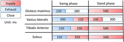
We designed a walking pattern (Figure ) sequence based on the investigations of the activation of the human muscles during bipedal walking [Citation42], and previous musculoskeletal biped walking robotic research [Citation16,Citation43] and tuned it through empirical testing that made sure the robot can walk over three steps without falling. This walking pattern was programmed into the Raspberry 3 and connected to Arduino Duo microcontroller using a custom signal amplifier board to control the activation of the pneumatic solenoid valves and PAMs. Both legs were actuated by the same control sequence in an alternating pattern. Two force sensing resistors (Interlink Electronics FSR 400) were installed at the heel of the feet to detect the heel contact and determine the switching. With these settings, the robot's average walking speed was approximately 0.7 m/s, and it ensured that the robot can continuously walk without falling. In this study, because it is difficult to completely start from the same initial position, the yaw moment was measured at non-steady-state walking.
Figure A1. The single leg walking pattern.